Format: Interactive PDF (Printable Document)
File Language: Operation Manual: English, Maintenance Manual: English, Technical Manual: English, Parts Manual: English
File Size: 607.20 MB (Speed Download Link)
Brand: Sandvik
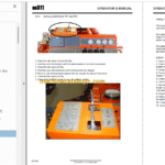
Model: DD311 Drilling Rig
No: L19D7031
Type of Document: Full Toolman Manual (Service, Operator, Maintenance Manual and Parts Catalog)
The language on the cover page and the product itself may differ
$ 150
BÖLÜM 01 GENERAL INFORMATIONS
INFORMATIONS GENERAL
INFORMACIONES GENERALES
GENEL BİLGİLER
BÖLÜM 02 LUBRICATION
LUBRIFICATION
LUBRICACION
GRES YAĞI İLE YAĞLAMA
BÖLÜM 03 ROCK DRILL
PERFORATEUR
PERFORADOR
KAYA DELİCİ
BÖLÜM 04 DRILL FEED – TURRET
GLISSIERE – TOURELLE
DESLIZADERA – TORRETA
DELME BESLEMELİ TARET
BÖLÜM 05 BOOM
BRAS
BRAZO
ÇUBUK
BÖLÜM 06 HYDRAULIC COMPONENTS
COMPOSANTS HYDRAULIQUE
EQUIPO HYDRAULICO
HİDROLİK SİSTEM PARÇALARI
BÖLÜM 07 TRAMMING COMPONENTS
CHAINE CINEMATIQUE
TRANSLACION
YÜRÜYÜŞ SİSTEMİ PARÇALARI
BÖLÜM 08 DIESEL ENGINE
GROUPE DIESEL
MOTOR DIESEL
DİZEL MOTOR
BÖLÜM 09 AIR FLUSHING CIRCUIT
CIRCUIT INJECTION AIR
INYECCION DE AIRE
HAVA PÜSKÜRTME DEVRESİ
BÖLÜM 10 WATER FLUSHING CIRCUIT
CIRCUIT INJECTION EAU
INEYCCION DE AGUA
SU YIKAMA DEVRESİ
BÖLÜM 11 ELECTRIC EQUIPMENT
EQUIPEMENT ELECTRIQUE
EQUIPO ELECTRICO
ELEKTRİK DONANIMI
BÖLÜM 12 OPTIONAL EQUIPMENT
EQUIPMENT OPTIONNEL
EQUIPO OPCION
OPSIYONLU DONANIMI
SECTION 1 HYDRAULIC AND ELECTRIC DIAGRAM
SCHEMAS HYDRAULIQUES ET ELECTRIQUES
SECTION 2 ROCK DRILL, FLUSHING HEAD
PERFORATEUR, TETE D’INJECTION
SECTION 3 DRILL FEED
GLISSIERE
SECTION 4 BOOM
BRAS
SECTION 5 DRILLING COMPARTMENT
POSTE DE FORATION
SECTION 6 COMPOSANTS HYDRAULIQUES DE FORATION
DRILLING HYDRAULIC COMPONENTS
SECTION 7 TRAMMING COMPARTMENT
POSTE DE CONDUITE
SECTION 8 DIESEL POWER PACK
GROUPE THERMO HYDRAULIQUE
SECTION 9 POWER TRAIN
CHAINE CINÉMATIQUE
SECTION 10 ELECTRIC POWER PACK
GROUPE ELECTRO HYDRAULIQUE
SECTION 11 ELECTRIC COMPONENTS
COMPOSANTS ELECTRIQUES
SECTION 12 WATER FLUSHING CIRCUIT
CIRCUIT INJECTION EAU
SECTION 13 COMPRESSED AIR CIRCUIT
CIRCUIT AIR COMPRIME
SECTION 14 HYDRAULIC TANK
RESERVOIR HYDRAULIQUE
SECTION 15 CARRIER
PORTEUR
SECTION 16 SAFETY CANOPY / CABIN
TOIT DE PROTECTION / CABINE
SECTION 17 OPTIONAL EQUIPMENT
OPTIONS
SECTION 18 HYDRAULIC HOSES
FLEXIBLES HYDRAULIQUES
SECTION 19 SPECIAL EQUIPMENTS
EQUIPEMENTS SPECIAUX
1. INTRODUCTION ……………………………………………………………………………….12
1.1. The purpose of instructions………………………………………………….. 12
1.2. Identification ………………………………………………………………………… 12
1.2.1. Product type and serial number………………………………………………………….. 12
1.2.2. Product manufacturer ……………………………………………………………………….. 13
1.2.3. Manuals ………………………………………………………………………………………….. 13
1.2.4. How to identify the correct manual for the product ………………………………… 13
1.2.5. Validity of the manuals ……………………………………………………………………… 13
1.2.6. Marking of the product………………………………………………………………………. 14
1.3. Copyright notice…………………………………………………………………… 15
1.4. Definitions …………………………………………………………………………… 15
2. SAFETY AND ENVIRONMENTAL INSTRUCTIONS ……………………………..18
2.1. Safety labels, safety messages and signals…………………………… 18
2.1.1. Signal words ……………………………………………………………………………………. 18
2.1.2. General hazard symbol …………………………………………………………………….. 18
2.1.3. Mandatory actions symbols ……………………………………………………………….. 19
2.1.4. Prohibited actions symbols………………………………………………………………… 20
2.1.5. Hazard symbols……………………………………………………………………………….. 21
2.1.6. Labels on product …………………………………………………………………………….. 24
2.2. User obligations …………………………………………………………………… 32
2.2.1. Managing work related hazards …………………………………………………………. 33
2.2.2. Scheduled safety inspections and preventive maintenance……………………. 33
2.2.3. Personal protective equipment …………………………………………………………… 34
2.3. Product limitations……………………………………………………………….. 35
2.3.1. Intended use……………………………………………………………………………………. 35
2.3.2. Prohibited use………………………………………………………………………………….. 35
2.3.3. Center of gravity ………………………………………………………………………………. 36
2.3.4. Maximum inclination angles during tramming and parking……………………… 37
2.3.5. Maximum inclinations angles during operating……………………………………… 37
2.3.6. Modifications ……………………………………………………………………………………. 38
2.4. Hazard zones ……………………………………………………………………….. 39
2.4.1. During drilling and boom movements ………………………………………………….. 41
2.4.2. Operator visibility ……………………………………………………………………………… 43
2.5. Safeguarding ……………………………………………………………………….. 46
2.5.1. Guards ……………………………………………………………………………………………. 46
2.5.2. Safety cabin …………………………………………………………………………………….. 49
2.5.3. Safety telescopic canopy …………………………………………………………………… 50
2.5.4. Access detector (Optional)…………………………………………………………………. 51
2.6. Complementary protective measures ……………………………………. 52
2.6.1. Use of emergency stop function …………………………………………………………. 52
2.6.2. Inhibition switches…………………………………………………………………………….. 53
2.6.3. Use of emergency/parking or ABA (Optional) brakes …………………………….. 54
2.6.4. Use of batteries master switches and circuit breaker……………………………… 56
2.6.5. Safety wire on the feed (only with rod retainer) …………………………………….. 58
2.6.6. Emergency exit ………………………………………………………………………………… 59
2.6.7. Safe access to machinery and three point support………………………………… 60
2.6.8. Fire risk control measures………………………………………………………………….. 61
2.7. Protection against emission hazards…………………………………….. 71
2.7.1. Noise………………………………………………………………………………………………. 71
2.7.2. Vibration………………………………………………………………………………………….. 71
2.7.3. Dust………………………………………………………………………………………………… 72
2.8. Emergency procedures ………………………………………………………… 73
2.9. Safety considerations for maintenance …………………………………. 74
2.9.1. Daily inspections and tasks for operators …………………………………………….. 74
2.9.2. Tasks which require definite technical skills and maintenance training …….. 75
2.10. Environment ………………………………………………………………………… 76
2.10.1. Decommissioning……………………………………………………………………………. 76
2.10.2. Dismantling ……………………………………………………………………………………. 76
2.10.3. Disposal ………………………………………………………………………………………… 77
2.11. Potential product related hazards identified by the user ………… 78
2.12. Incident reporting…………………………………………………………………. 78
7 (340)
3. INTRODUCTION TO PRODUCT …………………………………………………………80
3.1. Machine orientation ……………………………………………………………… 80
3.2. Main circuits and components………………………………………………. 80
3.3. Instruments and controls ……………………………………………………… 95
3.3.1. Tramming compartment ……………………………………………………………………. 95
3.3.2. Drilling compartment……………………………………………………………………….. 105
3.4. Main fuses and circuit breakers…………………………………………… 119
3.4.1. Standard electric cabinet ………………………………………………………………… 119
3.4.2. 1000V electric cabinet …………………………………………………………………….. 122
3.4.3. ULC/CSA electric cabinet ………………………………………………………………… 124
3.4.4. Fault current and overcurrent protection switchgear VYK (Optional) ……… 126
4. OPERATING INSTRUCTIONS ………………………………………………………….130
4.1. Operator’s instructions……………………………………………………….. 130
4.2. Main safety hazards in use or maintenance work…………………. 131
4.3. Electric system operator’s safety instructions……………………… 133
4.4. Assembly and checking of a new machine ………………………….. 135
4.5. Daily checks……………………………………………………………………….. 136
4.5.1. Checking the tires condition, pressure and nuts tightness ……………………. 139
4.5.2. Routine checks before starting a shift ……………………………………………….. 141
4.6. Brakes tests ……………………………………………………………………….. 159
4.6.1. Emergency / parking brake test………………………………………………………… 161
4.6.2. Service brake tests …………………………………………………………………………. 163
4.7. Tramming …………………………………………………………………………. 165
4.7.1. Machine in tramming and parking positions ……………………………………….. 165
4.7.2. Starting the engine …………………………………………………………………………. 167
4.7.3. Electric cable …………………………………………………………………………………. 172
4.7.4. Inhibition switches ………………………………………………………………………….. 174
4.7.5. Moving the machine ……………………………………………………………………….. 175
4.7.6. Stopping the machine……………………………………………………………………… 177
4.7.7. Parking the machine……………………………………………………………………….. 178
4.7.8. Setting-up the machine in the drift…………………………………………………….. 179
4.7.9. Use of stabilizers…………………………………………………………………………….. 181
4.7.10. Electric power ………………………………………………………………………………. 182
4.7.11. Access detector (Optional)……………………………………………………………… 184
4.8. Drilling …………………………………………………………………………. 192
4.8.1. Parallelism setting…………………………………………………………………………… 192
4.8.2. Drilling functionality …………………………………………………………………………. 194
4.8.3. Setting of drill feeds TTF and TFX …………………………………………………….. 202
4.8.4. Collaring a hole ………………………………………………………………………………. 204
4.8.5. Normal drilling ………………………………………………………………………………… 204
4.8.6. Some drilling tips…………………………………………………………………………….. 206
4.8.7. Drilling parameters………………………………………………………………………….. 207
4.8.8. During drilling …………………………………………………………………………………. 209
4.8.9. Drilling imperatives………………………………………………………………………….. 209
4.8.10. Changing the drill steel / drill bit ………………………………………………………. 210
4.9. Ending a shift……………………………………………………………………… 217
5. RADIO CONTROLLED DRILLING OPERATIONS (OPTIONAL) …………..220
5.1. Main components ………………………………………………………………. 221
5.2. Starting radio controlled operations ……………………………………. 224
5.2.1. Diesel mode …………………………………………………………………………………… 224
5.2.2. Electric mode …………………………………………………………………………………. 226
5.3. Radio control ……………………………………………………………………… 228
5.3.1. Selection of drilling or boom movements mode …………………………………… 228
5.3.2. Return to main menu or mode switch ………………………………………………… 228
5.3.3. Boom movements mode ………………………………………………………………….. 230
5.3.4. Drilling mode ………………………………………………………………………………….. 233
5.3.5. Cameras controls……………………………………………………………………………. 241
5.3.6. Other radio controlled functions ………………………………………………………… 245
5.4. Operating instructions………………………………………………………… 247
5.4.1. Using the control system display ………………………………………………………. 247
5.4.2. User interface controls …………………………………………………………………….. 247
5.4.3. User interface display ……………………………………………………………………… 250
5.4.4. Navigation in the user interface ………………………………………………………… 251
5.4.5. Warning messages …………………………………………………………………………. 254
9 (340)
5.5. Drilling …………………………………………………………………………. 257
6. ARCTIC PACKAGE (OPTIONAL) ……………………………………………………..260
6.1. Operating the Arctic package ……………………………………………… 260
6.2. Antifreeze tank……………………………………………………………………. 262
7. SPECIAL INSTRUCTIONS ……………………………………………………………….266
7.1. Removing the rod clamp from the drill feed …………………………. 266
7.2. Adjusting / replacing the rod clamp half guides …………………… 267
7.3. Use of stabilizers in case of diesel engine failure…………………. 268
7.4. Short distance towing…………………………………………………………. 272
7.5. Long distance towing …………………………………………………………. 278
7.5.1. Towing with the engine in operating condition…………………………………….. 278
7.5.2. Towing with a faulty engine ……………………………………………………………… 278
7.6. Electric cable end limit switches …………………………………………. 279
7.7. Transporting ………………………………………………………………………. 280
7.7.1. Transportation on a platform ……………………………………………………………. 280
7.8. Lifting methods and lifting points ……………………………………….. 282
7.9. Washing the rig ………………………………………………………………….. 285
7.10. Storing instructions ……………………………………………………………. 286
8. TROUBLESHOOTING ……………………………………………………………………..288
8.1. EMR2 Deutz electronic regulator …………………………………………. 289
8.1.1. Description of functions …………………………………………………………………… 289
8.1.2. Troubleshooting……………………………………………………………………………… 290
9. TECHNICAL SPECIFICATIONS ……………………………………………………….294
![Sandvik DD311 Drilling Rig Full Documents (Service, Operator, Maintenance Manual and Parts Catalog) [L19D7031]](https://machinecatalogic.com/wp-content/uploads/2025/05/107-14-150x150.png)


![Sandvik DD311 Drilling Rig Full Documents (Service, Operator, Maintenance Manual and Parts Catalog) [L19D7031]](https://machinecatalogic.com/wp-content/uploads/2025/05/107-14.png)

