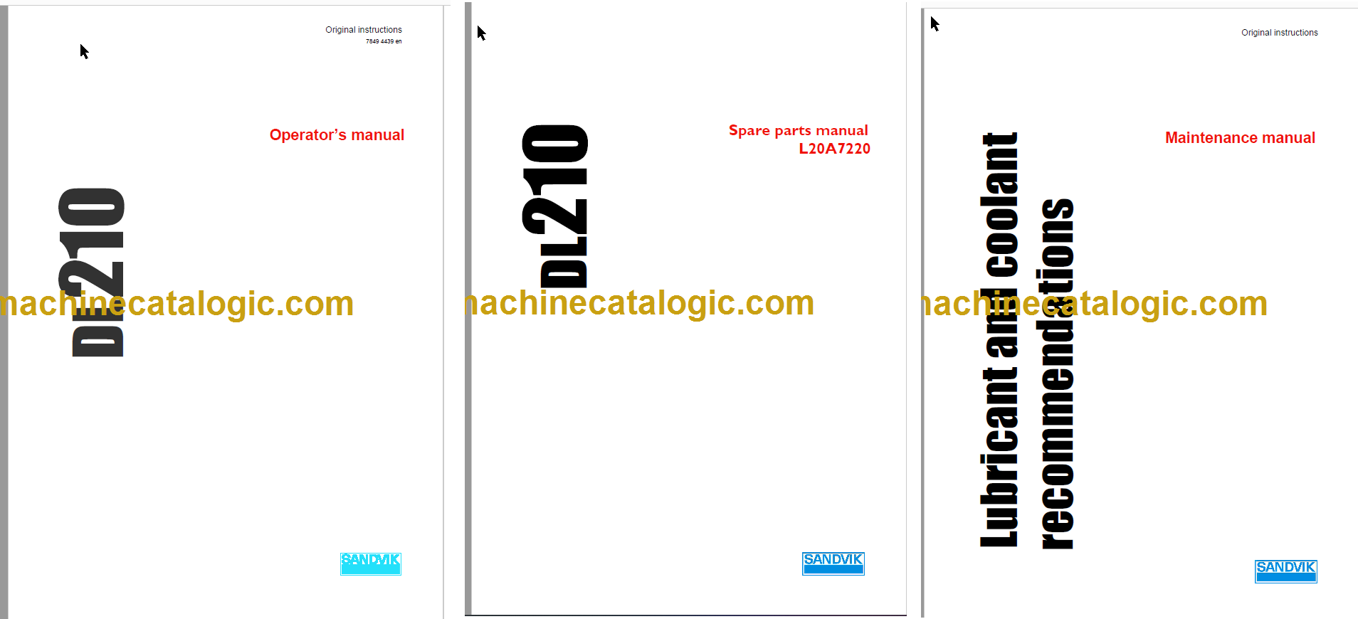
Format: Interactive PDF (Printable Document)
File Language: English and Spanish
Brand: Sandvik
Model: DL210
No:L20A7220
Type of Document: Service, Operator, Maintenance, Diagrams Manual and Parts Catalog
$ 150
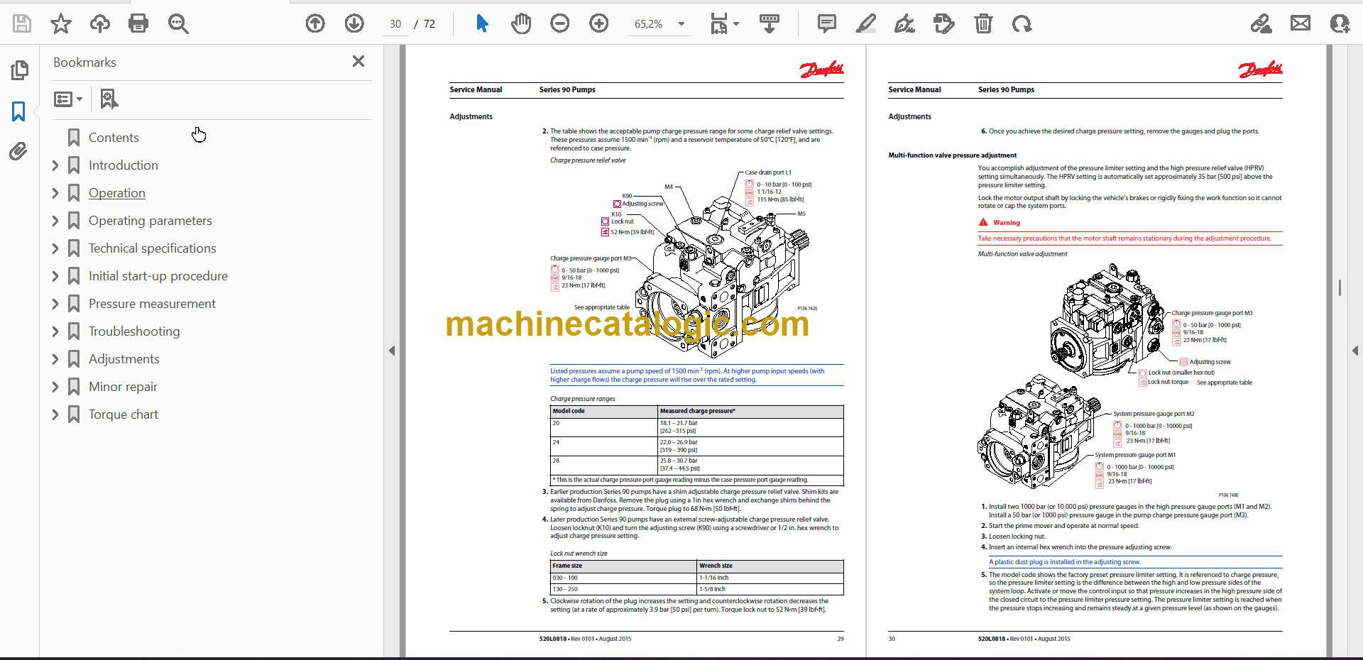
Service Manual
SECTION 02 LUBRICATION
SECTION 03 ROCK DRILL
SECTION 04 DRILL FEED – TURRET
SECTION 05 BOOM
SECTION 06 HYDRAULIC COMPONENTS
SECTION 07 TRAMMING COMPONENTS
SECTION 08 DIESEL ENGINE
SECTION 09 AIR FLUSHING CIRCUIT
SECTION 10 WATER FLUSHING CIRCUIT
SECTION 11 ELECTRIC EQUIPMENT
SECTION 12 OPTIONAL EQUIPMENT
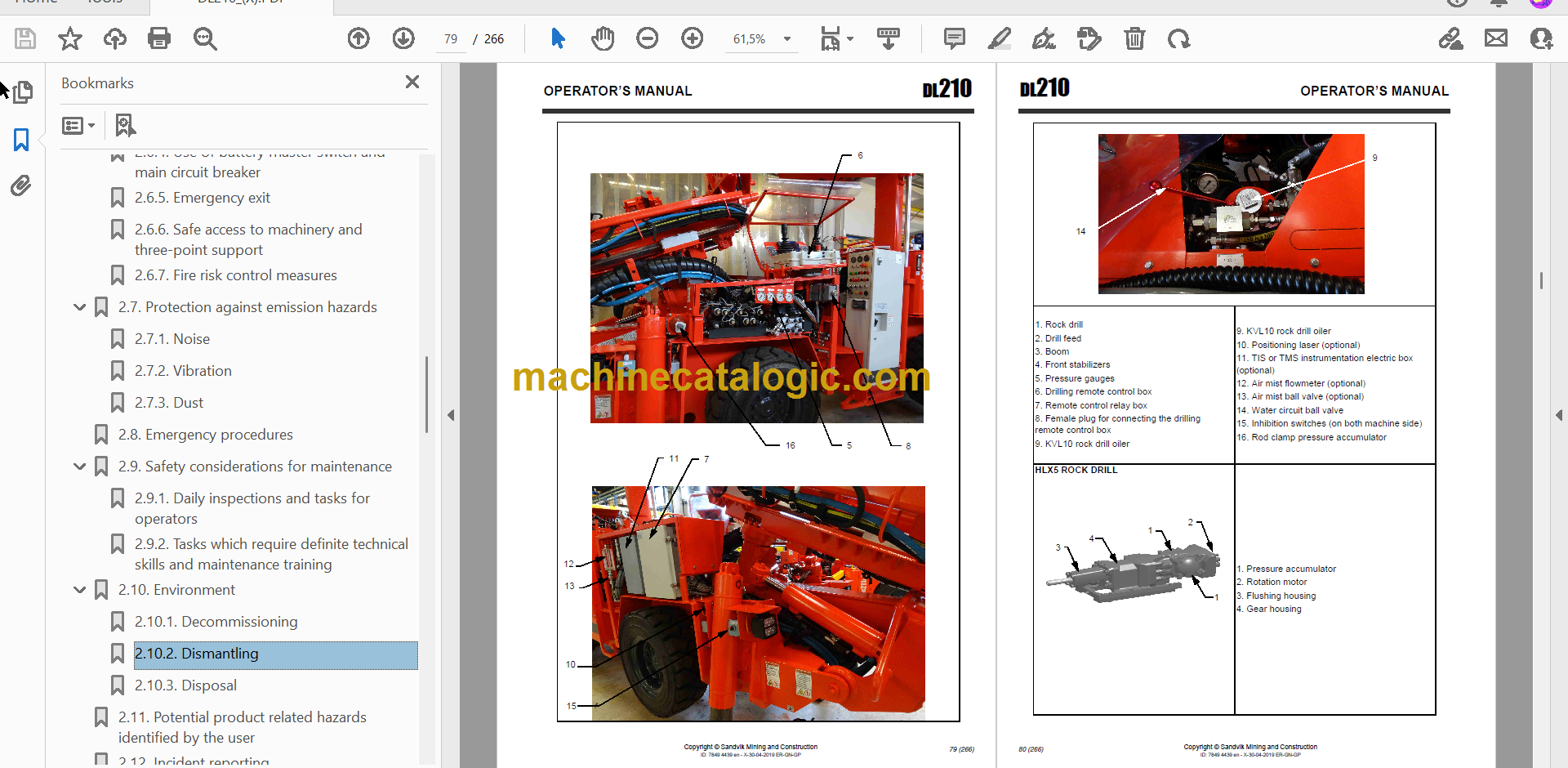
Operator Manual
1. INTRODUCTION ……………………………………………………………………………….12
1.1. The purpose of instructions………………………………………………….. 12
1.2. Identification………………………………………………………………………… 12
1.2.1. Product type and serial number ………………………………………………………….. 12
1.2.2. Product manufacturer ……………………………………………………………………….. 13
1.2.3. Manuals ………………………………………………………………………………………….. 13
1.2.4. How to identify the correct manual for the product ………………………………… 13
1.2.5. Validity of the manuals ……………………………………………………………………… 13
1.2.6. Marking of the product ………………………………………………………………………. 14
1.3. Copyright notice…………………………………………………………………… 16
1.4. Definitions …………………………………………………………………………… 16
2. SAFETY AND ENVIRONMENTAL INSTRUCTIONS ……………………………..20
2.1. Safety labels, safety messages and signals…………………………… 20
2.1.1. Signal words ……………………………………………………………………………………. 20
2.1.2. General hazard symbol …………………………………………………………………….. 20
2.1.3. Mandatory actions symbols ……………………………………………………………….. 21
2.1.4. Prohibited actions symbols ………………………………………………………………… 22
2.1.5. Hazard symbols ……………………………………………………………………………….. 23
2.1.6. Labels on product …………………………………………………………………………….. 26
2.2. User obligations …………………………………………………………………… 35
2.2.1. Managing work related hazards …………………………………………………………. 36
2.2.2. Scheduled safety inspections and preventive maintenance ……………………. 36
2.2.3. Personal protective equipment …………………………………………………………… 37
2.3. Product Limitations………………………………………………………………. 38
2.3.1. Intended use ……………………………………………………………………………………. 38
2.3.2. Prohibited use ………………………………………………………………………………….. 38
2.3.3. Centre of gravity ………………………………………………………………………………. 39
Copyright © Sandvik Mining and Construction
ID: 7849 4439 en – X-30-04-2019 ER-GN-GP
DL210 OPERATOR’S MANUAL
6 (266)
2.3.4. Maximum inclination angles during tramming and parking ……………………… 41
2.3.5. Maximum inclinations angles during operating ……………………………………… 41
2.3.6. Modifications ……………………………………………………………………………………. 42
2.4. Hazard zones ……………………………………………………………………….. 43
2.4.1. During tramming and setting up ………………………………………………………….. 43
2.4.2. During drilling and boom movements ………………………………………………….. 44
2.4.3. Operator’s visibility ……………………………………………………………………………. 46
2.5. Safeguarding ……………………………………………………………………….. 48
2.5.1. Guards ……………………………………………………………………………………………. 48
2.5.2. Safety telescopic canopy …………………………………………………………………… 50
2.6. Complementary protective measures ……………………………………. 51
2.6.1. Use of emergency stop function …………………………………………………………. 51
2.6.2. Drilling inhibition switches ………………………………………………………………….. 54
2.6.3. Use of ABA emergency/parking brakes ……………………………………………….. 55
2.6.4. Use of battery master switch and main circuit breaker …………………………… 57
2.6.5. Emergency exit ………………………………………………………………………………… 59
2.6.6. Safe access to machinery and three-point support ………………………………… 59
2.6.7. Fire risk control measures ………………………………………………………………….. 60
2.7. Protection against emission hazards…………………………………….. 69
2.7.1. Noise ………………………………………………………………………………………………. 69
2.7.2. Vibration ………………………………………………………………………………………….. 69
2.7.3. Dust ………………………………………………………………………………………………… 70
2.8. Emergency procedures ………………………………………………………… 71
2.9. Safety considerations for maintenance …………………………………. 72
2.9.1. Daily inspections and tasks for operators …………………………………………….. 72
2.9.2. Tasks which require definite technical skills and maintenance training …….. 73
2.10. Environment ………………………………………………………………………… 74
2.10.1. Decommissioning ……………………………………………………………………………. 74
2.10.2. Dismantling ……………………………………………………………………………………. 74
2.10.3. Disposal ………………………………………………………………………………………… 74
2.11. Potential product related hazards identified by the user ………… 76
2.12. Incident reporting…………………………………………………………………. 76
3. INTRODUCTION TO PRODUCT …………………………………………………………78
3.1. Machine orientation ……………………………………………………………… 78
3.2. Main circuits and components………………………………………………. 78
3.3. Tramming compartment instruments and controls………………… 86
3.4. Drilling remote control box …………………………………………………… 92
3.5. TIS data displaying unit (optional)……………………………………….. 112
3.6. Main fuses and circuit breakers…………………………………………… 113
3.6.1. Control panel …………………………………………………………………………………. 113
3.6.2. Standard & ULC-CSA main switch and circuit breakers ……………………….. 116
3.6.3. 1000V main switch and circuit breakers …………………………………………….. 117
3.6.4. Fault current and overcurrent protection switchgear VYK (optional) ………. 118
4. OPERATING INSTRUCTIONS ………………………………………………………….122
4.1. Operator’s instructions……………………………………………………….. 122
4.2. Main safety hazards in use or maintenance work…………………. 123
4.3. Electric system operator’s safety instructions……………………… 125
4.4. Assembly and checking of a new machine ………………………….. 127
4.5. Daily checks……………………………………………………………………….. 128
4.5.1. Checking the tires condition, pressure and nuts tightness ……………………. 130
4.5.2. Routine checks before starting a shift ……………………………………………….. 132
4.6. Emergency/parking brake test …………………………………………….. 143
4.7. Tramming …………………………………………………………………………. 146
4.7.1. Machine in tramming and parking positions ………………………………………. 146
4.7.2. Starting the engine …………………………………………………………………………. 148
4.7.3. Electric cable …………………………………………………………………………………. 150
4.7.4. Moving the machine ……………………………………………………………………….. 153
4.7.5. Stopping the machine ……………………………………………………………………… 156
4.7.6. Parking the machine ……………………………………………………………………….. 157
4.8. Drilling …………………………………………………………………………. 158
4.8.1. Setting-up the machine in the drift …………………………………………………….. 158
4.8.2. Use of stabilizers ……………………………………………………………………………. 161
4.8.3. Electric power ………………………………………………………………………………… 162
Copyright © Sandvik Mining and Construction
ID: 7849 4439 en – X-30-04-2019 ER-GN-GP
DL210 OPERATOR’S MANUAL
8 (266)
4.8.4. Electric control panel ……………………………………………………………………….. 163
4.8.5. Motor start-up …………………………………………………………………………………. 163
4.8.6. Drilling functionality …………………………………………………………………………. 164
4.8.7. Safety wire on the feed (only when no rod magazine) ………………………….. 173
4.8.8. Before drilling …………………………………………………………………………………. 177
4.8.9. Collaring ………………………………………………………………………………………… 178
4.8.10. Normal drilling ………………………………………………………………………………. 179
4.8.11. Rod uncoupling …………………………………………………………………………….. 180
4.8.12. Next rod coupling manual operation ………………………………………………… 181
4.8.13. Next rod coupling using the rod magazine system …………………………….. 183
4.8.14. Rod coupling with the rod handler system ………………………………………… 187
4.8.15. Some drilling tips …………………………………………………………………………… 190
4.8.16. Drilling parameters ………………………………………………………………………… 191
4.8.17. During drilling ……………………………………………………………………………….. 193
4.8.18. Feed return ………………………………………………………………………………….. 193
4.8.19. Manual percussion ………………………………………………………………………… 193
4.8.20. Drilling imperatives ………………………………………………………………………… 194
4.8.21. Changing the drill steel / drill bit ………………………………………………………. 195
4.9. Special circumstances………………………………………………………… 203
4.9.1. Removing a jammed drilling rod ……………………………………………………….. 203
4.9.2. Shank change procedure …………………………………………………………………. 204
4.10. Ending a shift……………………………………………………………………… 209
5. ARCTIC PACKAGE (OPTIONAL) ……………………………………………………..212
5.1. Operating the Arctic package ……………………………………………… 213
5.2. Antifreeze tank……………………………………………………………………. 214
5.3. Water tank filling ………………………………………………………………… 216
6. SPECIAL INSTRUCTIONS ……………………………………………………………….218
6.1. Removing the rod clamp from LHF feed and replacing its half
guides …………………………………………………………………………. 218
6.2. Use of stabilizers in case of diesel engine failure
(default mode)…………………………………………………………………….. 221
6.3. Short distance towing…………………………………………………………. 225
6.4. Cable end limit switches……………………………………………………… 230
6.5. Transporting ………………………………………………………………………. 231
6.5.1. Transportation on a platform ……………………………………………………………. 231
6.6. Lifting methods and lifting points ……………………………………….. 233
6.7. Washing the rig ………………………………………………………………….. 236
6.8. Storing instructions ……………………………………………………………. 237
7. TROUBLESHOOTING ……………………………………………………………………..240
8. TECHNICAL SPECIFICATIONS ……………………………………………………….242
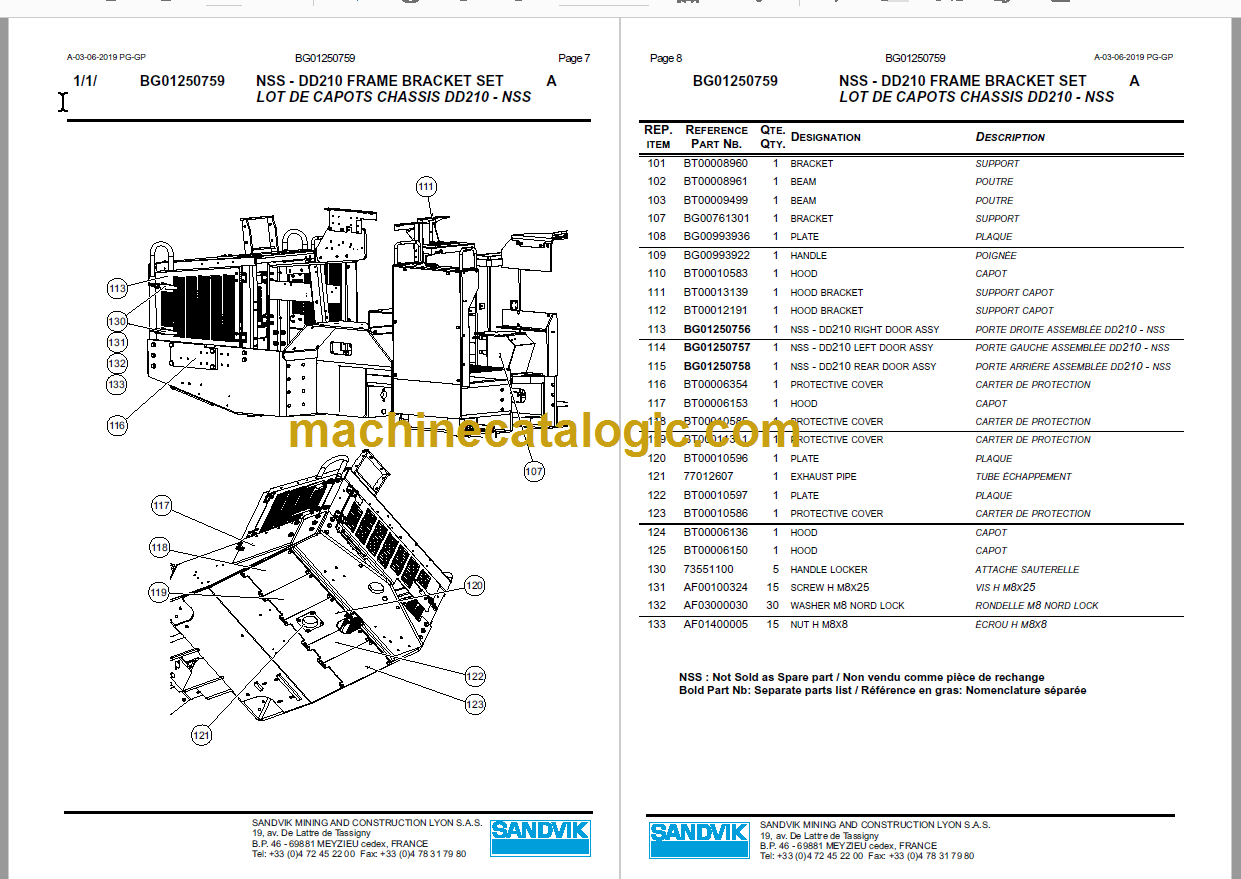
Parts Manual
SECTION 1 HYDRAULIC AND ELECTRIC DIAGRAMS
SECTION 2 ROCK DRILL, FLUSHING HEAD
SECTION 3 DRILL FEED
SECTION 4 BOOM
SECTION 5 DRILLING COMPARTMENT
SECTION 6 DRILLING HYDRAULIC COMPONENTS
SECTION 7 TRAMMING COMPARTMENT
SECTION 8 DIESEL POWER PACK
SECTION 9 POWER TRAIN
SECTION 10 ELECTRIC POWER PACK
SECTION 11 ELECTRIC COMPONENTS
SECTION 12 WATER FLUSHING CIRCUIT
SECTION 13 COMPRESSED AIR CIRCUIT
SECTION 14 HYDRAULIC TANKS
SECTION 15 CARRIER
SECTION 16 SAFETY CANOPY
SECTION 17 OPTIONAL EQUIPMENTS
SECTION 18 HYDRAULIC HOSES
SECTION 19 SPECIAL EQUIPMENTS
![Sandvik DL210 Underground Drill Rig Full Documents (Service, Operator, Maintenance Manual and Parts Catalog) [L20A7220]](https://machinecatalogic.com/wp-content/uploads/2026/07/DL210_combined-150x150.png)


![Sandvik DL210 Underground Drill Rig Full Documents (Service, Operator, Maintenance Manual and Parts Catalog) [L20A7220]](https://machinecatalogic.com/wp-content/uploads/2026/07/DL210_combined-768x350.png)