Takeuchi TB108 Mini Excavator Parts Manual (BB5Z105-7-0) (SN 10820001- 10822112, 108202113-)
That TB108 usually lives in tight spots—backyards, inside buildings, along foundations—anywhere a big machine won’t fit. This parts manual helps you trace every assembly on the mini ex, break it down into sub-components, and match what’s in your hands to the right part number. Say you’ve got the track off, adjuster out, and you’re staring at a mangled seal and a mystery snap ring; this book lets you isolate that exact ring, verify it against the diagram, and order the right piece the first time.
Applications & Use Cases
- Track down which undercarriage roller you’ve actually got, then check the exploded view to confirm the seals, pins, and hardware before you order.
- When a control lever feels sloppy, you can inspect the linkage diagram, trace each bushing and washer, and avoid guessing at what’s worn.
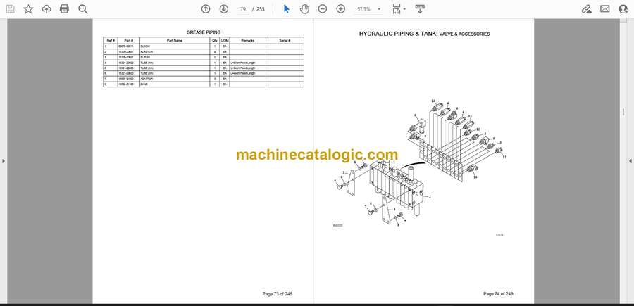
- During a hose replacement, route new lines correctly by following the hydraulic system breakdown instead of copying someone’s old patch job.
- If you’re rebuilding the blade or boom pivot, test your parts list against the diagram so you don’t miss shims, spacers, or that odd-sized snap ring.
- Keep the shop organized by aligning your stock bins to the manual’s part numbers and assemblies, so reorders are quick and clean.
FAQ
Q: Is this a searchable PDF or just scanned pages?
A: It’s typically a PDF you can scroll and zoom; search may work on text sections, but plan on using the index and diagrams like a paper book.
Q: Can I print just the pages I need to take to the jobsite?
A: Yes, most folks print the systems they’re working on, mark them up, and keep the clean master file on a computer.
Safety Note
Always support the machine and relieve hydraulic pressure before you tear into any component you’ve traced in this manual.
Takeuchi TB108 Mini Excavator Index:
- UNDERCARRIAGE 1
- LOWER FRAME 2
- CRAWLER BELT 4
- TRACK ROLLER 6
- FRONT IDLER 8
- TRACK ADJUSTER 10
- TRAVEL DEVICE 12
- SLEW BEARING 14
- SWIVEL JOINT & ACCESSORIES 16
- DOZER BLADE 18
- PIPING; LOWER 20
- TURNTABLE & CONTROL LEVER 22
- SLEWING DEVICE 23
- TURNTABLE 26
- BOOM SWING 28
- SLEW LOCK 30
- TRAVEL LEVER 32
- OPERATION LEVER 36
- SWING PEDAL & AUX. PEDAL 38
- DOZER BLADE LEVER 40
- STAND 42
- FRONT PIPE 46
- ENGINE & ELECTRICAL SYSTEM 48
- ENGINE & ACCESSORIES (1/2) 49
- ENGINE & ACCESSORIES (2/2) 52
- AIR CLEANER (for double element) 54
- DRAIN PLUG 56
- CONTROL BOX 58
- ENGINE CONTROL 60
- ELECTRICAL 62
- TRAVEL ALARM 64
- BATTERY 66
- MAINTENANCE LIGHT SOCKET 68
- HYDRAULIC PIPING & TANK 70
- GREASE PIPING 71
- VALVE & ACCESSORIES 74
- PIPING; UPPER (1/2) 76
- PIPING; UPPER (2/2) 78
- PUMP DRIVE 80
- HYDRAULIC TANK 82
- FUEL TANK & FUEL PIPING 84
- COVER & CAB 88
- COVER (1/2) 89
- COVER (2/2) (engine hood) 94
- SEAT 96
- SEAT BELT 98
- SEAT BELT (retractable type) 100
- CANOPY 102
- CANOPY (with hook) 104
- TOOL BOX 106
- HOE ATTACHMENT 108
- BOOM 109
- ARM 114
- AUXILIARY LINE 116
- DECAL & TOOL 118
- DECAL-1 119
- DECAL-2 126
- TOOL & ACCESSORIES 132
- PAINTED COLOR 134
- HYDRAULIC DEVICE 136
- SWIVEL JOINT 137
- CONTROL VALVE-1 142
- CONTROL VALVE-2 144
- HOUSING ASSY 1 146
- BLOCK ASSY; No. 1 148
- BLOCK ASSY; No. 2 150
- BLOCK ASSY; No. 3 152
- BLOCK ASSY; No. 4 154
- BLOCK ASSY; No. 5 156
- BLOCK ASSY; No. 6 158
- BLOCK ASSY; No. 7 160
- BLOCK ASSY; No. 8 162
- HOUSING ASSY 2 164
- BOOM CYLINDER (108200001-108201317) 166
- BOOM CYLINDER (108201318-) 168
- ARM CYLINDER 170
- BUCKET CYLINDER 172
- DOZER BLADE CYLINDER 174
- SWING CYLINDER 176
- SPAN CYLINDER 178
- TRAVEL MOTOR (1/3) (reduction sec.) 180
- TRAVEL MOTOR (2/3) (motor sec.) 182
- TRAVEL MOTOR (3/3) (valve sec.) 184
- SLEW MOTOR 186
- HYDRAULIC PUMP 188
- ENGINE – YANMAR 2TNV70-PTB SN 10820001-10822112,108202113- 190
- Fig1.CYLINDER BLOCK 191
- Fig2.GEAR HOUSING 194
- Fig3.FLYWHEEL HOUSING & OIL SUMP 196
- Fig4.CYLINDER HEAD & BONNET 198
- Fig5.AIR CLEANER 202
- Fig6.EXHAUST MANIFOLD & SILENCER 204
- Fig7.CAMSHAFT & DRIVING GEAR 206
- Fig8.CRANKSHAFT & PISTON 208
- Fig9.LUB.OIL SYSTEM 210
- Fig10.COOLING WATER SYSTEM 212
- Fig11.FUEL INJECTION PUMP 214
- Fig12.GOVERNOR 218
- Fig13.FUEL INJECTION VALVE 222
- Fig14.FUEL LINE 224
- Fig15.STARTING MOTOR 226
- Fig16.GENERATOR 228
- Fig17.GASKET SET 230
- KITS, ATTACHMENTS & QUICK REFERENCE 232
Takeuchi


