$ 0
0
$ 0
0

Takeuchi TB175 Compact Excavator Workshop Manual (CL3E004)

Format: PDF (Printable Document)

File Language: English

File Pages: 980

File Size: 24.00 MB (Speed Download Link)

Brand: Takeuchi

Model: TB175 Compact Excavator

Book No: CL3E004

Serial No: 17510003-

Type of Document: Workshop Manual

Categories: ,

$ 50

Share:

Takeuchi TB175 Compact Excavator Workshop Manual (CL3E004)

Takeuchi TB175 Compact Excavator Workshop Manual (CL3E004) (SN 17510003-)

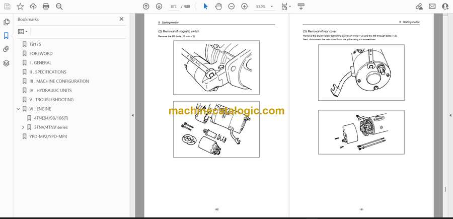
On a TB175 that spends its life trenching, loading trucks, and working around utilities, this workshop manual is what I’d keep open on the bench or tablet. It walks you through structured repair sequences so you’re not guessing when you’ve got a boom cylinder weeping, a swing motor acting up, or the travel motors losing power under load. For example, if the house starts to swing unevenly or drifts on a slope, I’d use this manual to trace the hydraulic circuit step by step, inspect the components in order, and then reinstall everything with the right checks so it’s safe to go back in the dirt.

Applications & Use Cases

  • Trace hydraulic faults methodically and isolate whether the issue is in the pump, valve bank, or actuator.
  • Follow a clear sequence to remove, overhaul, and reinstall major components like final drives or swing assemblies.
  • Verify linkage alignment and machine geometry after pin and bushing replacements.
  • Inspect structural parts for wear or cracking and decide if they can be reused or must be replaced.
  • Bleed hydraulic lines and test functions safely after hose, cylinder, or component changes.

FAQ

Q: Can I use this manual on a tablet in the field?

A: Yes, it’s practical on a tablet; you can zoom diagrams and keep it beside the machine while you work.

Q: Is it worth printing sections of this manual?

A: Printing the procedures you use often is handy—you can mark notes, oil stains don’t matter, and you’re not worried about dropping a device.

Safety Note

Always lock out, support, and depressurize the TB175 properly before opening any hydraulic or structural assembly.

📘 Show Index

Takeuchi TB175 Compact Excavator Index:

  • TB175
  • FOREWORD
  • I . GENERAL
  • II . SPECIFICATIONS
  • III . MACHINE CONFIGURATION
  • IV . HYDRAULIC UNITS
  • V . TROUBLESHOOTING
  • VI . ENGINE
    • 4TNE94/98/106(T)
    • 3TNV/4TNV series
      • Cover
      • History of Revision
      • PREFACE
      • SAFETY LABELS
      • CONTENTS
      • 1. General
        • 1.1 Engine nomenclature
        • 1.2 Specifications
        • 1.3 Fuel oil, lubricating oil and cooling water
          • 1.3.1 Fuel oil
          • 1.3.2 Lubricating oil
          • 1.3.3 Cooling water
        • 1.4 Engine external views
        • 1.5 Structural description
        • 1.6 Exhaust gas emission regulation
          • 1.6.1 The emission standard in USA
          • 1.6.2 Engine identification
          • 1.6.3 Guarantee conditions for the EPA emission standard
      • 2. Inspection and adjustment
        • 2.1 Periodic maintenance schedule
        • 2.2 Periodic inspection and maintenance procedure
          • 2.2.1 Check before daily operation
          • 2.2.2 inspection after initial 50 hours operation
          • 2.2.3 Inspection every 50 hours
          • 2.2.4 Inspection every 250 hours or 3 months
          • 2.2.5 Inspection every 500 hours or 6 months
          • 2.2.6 Inspection every 1,000 hours or one year
          • 2.2.7 Inspection every 2000 hours or 2 years
        • 2.3 Adjusting the no-load maximum or minimum speed
        • 2.4 Sensor inspection
          • 2.4.1 Oil pressure switch
          • 2.4.2 Thermo switch
        • 2.5 Water leak check in cooling water system
        • 2.6 Radiator cap inspection
        • 2.7 Thermostat Inspection
        • 2.8 Adjusting operation
        • 2.9 Long storage
      • 3. Troubleshooting
        • 3.1 Preparation before troubleshooting
        • 3.2 Quick reference table for troubleshooting
        • 3.3 Troubleshooting by measuring compression pressure
      • 4. Disassembly, inspection and reassembly of engines
        • 4.1 Complete disassembly and reassembly
          • 4.1.1 Introduction
          • 4.1.2 Special service tools
          • 4.1.3 Complete disassembly
          • 4.1.4 Precautions before and during reassembly
          • 4.1.5 Adjusting operation
        • 4.2 Cylinder head: Disassembly, inspection and reassembly
          • 4.2.1 Components (2-valve cylinder head)
          • 4.2.2 Disassembly procedure:
          • 4.2.3 Reassembly procedure:
          • 4.2.4 Servicing points
          • 4.2.5 Parts Inspection and measurement
          • 4.2.6 Valve seat correction
          • 4.2.7 Valve guide replacement
          • 4.2.8 Valve stem seal replacement
        • 4.3 Gear train and camshaft
          • 4.3.1 Components
          • 4.3.2 Disassembly procedure:
          • 4.3.3 Reassembly procedure:
          • 4.3.4 Servicing points
          • 4.3.5 Parts inspection and measurement
          • 4.3.6 Oil seal replacement (Gear case side)
          • 4.3.7 Camshaft bushing replacement
        • 4.4 Cylinder block
          • 4.4.1 Components
          • 4.4.2 Disassembly procedure:
          • 4.4.3 Reassembly procedure:
          • 4.4.4 Servicing points
          • 4.4.5 Parts inspection and measurement
          • 4.4.6 Cylinder bore correction
          • 4.4.7 Piston pin bushing replacement
          • 4.4.8 Oil seal replacement (Flywheel housing side)
      • 5. Lubrication system
        • 5.1 Lubrication system diagram
        • 5.2 Trochoid pump components
        • 5.3 Disassembly (Reverse the procedure below for assembly)
        • 5.4 Servicing points
        • 5.5 Parts Inspection and measurement
          • 5.5.1 Trochoid pump inspection and measurement
        • 5.6 Lube oil filter
          • 5.6.1 Lube oil filter construction
          • 5.6.2 Lube oil filter replacement
      • 6. Cooling system
        • 6.1 Cooling water system
        • 6.2 Cooling water pump components
        • 6.3 Disassembly (Reverse the procedure below for assembly)
        • 6.4 Servicing points
      • 7. Fuel injection pump / Governor
        • 7.1 Introduction
        • 7.2 Fuel injection pump
          • 7.2.1 Fuel system diagram
          • 7.2.2 External view and components
          • 7.2.3 Disassembly procedure:
          • 7.2.4 Assembly procedure
          • 7.2.5 Servicing points
          • 7.2.6 C.S.D. (Cold Start Device)
      • 8. Turbocharger: Disassembly, inspection and reassembly
        • 8.1 Structure and functions
          • 8.1.1 Main specifications
          • 8.1.2 Construction
          • 8.1.3 Structural and functional outline
          • 8.1.4 Components
        • 8.2 Service standards and tightening torque
          • 8.2.1 Service standards
          • 8.2.2 Tightening torque
        • 8.3 Periodic inspection procedure
          • 8.3.1 Periodic inspection intervals
          • 8.3.2 Inspection procedure
          • 8.3.3 Waste gate valve adjustment procedure
        • 8.4 Disassembly procedure
          • 8.4.1 Preparation for disassembly
          • 8.4.2 Inspection before disassembly
          • 8.4.3 Disassembly
        • 8.5 Washing and inspection procedure
          • 8.5.1 Washing
          • 8.5.2 Inspection procedure
        • 8.6 Reassembly procedure
          • 8.6.1 Preparation for reassembly
          • 8.6.2 Reassembly
        • 8.7 Handling after disassembly and reassembly
          • 8.7.1 Instructions for turbocharger installation
        • 8.8 Troubleshooting
          • 8.8.1 Excessively exhaust smoke
          • 8.8.2 White smoke generation
          • 8.8.3 Sudden oil decrease
          • 8.8.4 Decrease in output
          • 8.8.5 Poor (slow) response (starting) of turbocharger
          • 8.8.6 Abnormal sound or vibration
      • 9. Starting motror
        • 9.1 For 4TNV94L/ 98
          • 9.1.1 Specifications
          • 9.1.2 Components
          • 9.1.3 Troubleshooting
          • 9.1.4 Names of parts and disassembly procedure
          • 9.1.5 Inspection and maintenance
          • 9.1.6 Service standards
          • 9.1.7 Assembly
          • 9.1.8 Characteristic test
        • 9.2 For 4TNV106 (T)
          • 9.2.1 Specifications
          • 9.2.2 Congiguration drawing
          • 9.2.3 Troubleshooting
          • 9.2.4 Component names and disassembly procedure
          • 9.2.5 Disassembly procedure
          • 9.2.6 Inspection and maintenance
          • 9.2.7 Assembly
          • 9.2.8 Adjustment
          • 9.2.9 Service standards
        • 9.3 For 3TNV82A to 3/4TNV88
          • 9.3.1 Specifications
          • 9.3.2 Characteristics
          • 9.3.3 Disassembly drawing
          • 9.3.4 Connecting diagram of a starting motor
      • 10. Alternator
        • 10.1 The 40A alternator for 3TNV84 and other models
          • 10.1.1 Components
          • 10.1.2 Specifications
          • 10.1.3 Wiring diagram
          • 10.1.4 Standard output characteristics
          • 10.1.5 Inspection
          • 10.1.6 Troubleshooting
      • 11. Electric wiring
        • 11.1 Electric wiring diagram
        • 11.2 Precaution on electric wiring
          • 11.2.1 Alternator
          • 11.2.2 Starter
          • 11.2.3 Current limiter
          • 11.2.4 Section area and resistance of electric wire
      • 12. Service standards
        • 12.1 Engine tuning
        • 12.2 Engine body
          • 12.2.1 Cylinder head
          • 12.2.2 Gear train and camshaft
          • 12.2.3 Cylinder block
        • 12.3 Lubricating oil system (Trochoid pump)
      • 13. Tightening torque for bolts and nuts
      • Back cover
  • YPD-MP2/YPD-MP4

Takeuchi

Latest Product

0
    0
    Your Cart
    Your cart is emptyReturn to Shop