Takeuchi TB210R Mini Excavator Workshop Manual (CB8E013) (SN 211000004-)
On a small machine like the Takeuchi TB210R, working in tight residential yards, interior demolition, or utility trenches, you don’t have room for guesswork. This workshop manual is what I’d keep on the bench when I’m tearing into major components and putting them back together. It walks you through how to strip, inspect, and correctly reinstall parts so the machine tracks straight, swings smoothly, and digs without odd noises. For example, if the boom starts drifting or you’ve got a weak function after a hose blowout, this is the document I’d use to trace the fault, rebuild the affected components, and verify everything is bled and sealed before it goes back to work.
Applications & Use Cases
- Planning a full component teardown so you remove, support, and reinstall parts in a safe sequence.
- Tracing hydraulic issues by following a logical inspection order instead of swapping parts blindly.
- Checking wear limits and clearances during undercarriage or swing system service.
- Verifying linkage alignment after pin, bushing, or cylinder replacement.
- Confirming torque patterns and recheck points after major repairs to prevent early failures.
FAQ
Q: Can I keep this manual on a tablet in the field?
A: Yes, it’s practical to use digitally; you can zoom in on diagrams and search by keywords while you’re at the machine.
Q: Is it worth printing sections of this manual?
A: I’d print the procedures you use often, put them in plastic sleeves, and keep them near the work area so they don’t get ruined by oil and dirt.
Safety Note
Always lock out the machine, relieve system pressure, and support raised components before starting any repair guided by this manual.
Takeuchi TB210R Mini Excavator Index:
- REVISION HISTORY
- FOREWORD
- Directional terms: front, rear, left, right
- Machine serial number
- Symbols used in this manual
- Manual structure
- 1. SAFETY
- SAFETY ALERT SYMBOL
- SAFETY PRECAUTIONS
- Observe all safety rules
- Wear safe clothing and protective gear
- Install an extinguisher and a first aid kit
- Lockout/Tagout (LOTO)
- Use the correct tools
- Regularly replace the safety-critical parts
- Explosionproof lighting
- Prohibit access by unauthorized persons
- Prepare the work area
- When the canopy is tilted up
- Keep the machine clean
- Stop the engine before performing maintenance
- Keep clear of the moving fan and belt
- When working under the machine
- When working on the machine
- Securing the working equipment
- Secure the engine hood and guard when they are open
- Place heavy components in a stable position
- Caution when filling with fuel or oil
- Preventing Fire and Explosion
- Be careful with hot and pressurized components
- Handling of radiator
- Be careful with oils under pressure
- Release the residual pressure from the hydraulic system before performing maintenance
- Be careful with grease under pressure
- Handling of the accumulator
- Disconnect the battery
- Use caution when handling batteries
- Have a service agent repair welding cracks or other damage
- Checks after maintenance
- Disposing of wastes
- Always maintain 3 points of contact when getting on and off the machine.
- Cautions when starting the engine
- Do not allow anyone other than the operator on the machine.
- If the cab or canopy is damaged
- Beware of fragments when working with a hammer
- Precautions when performing maintenance on the air conditioner
- CAUTIONS WHEN WORKING
- Before starting work
- When disassembling or assembling
- When removing/installing the hydraulic unit
- When connecting/disconnecting the hoses or pipes
- Handling of seals
- Pressure adjustment for hydraulic devices
- 2. SERVICE DATA
- DIMENSIONAL DRAWING
- Machine dimensions
- Operating range
- SPECIFICATION TABLE
- Performance
- Completed machine dimensions
- Main unit dimensions
- Engine
- Hydraulic equipment
- Control equipment
- Slew equipment
- Lower machinery
- Working equipment
- Work dimensions
- Main construction
- Hydraulic cylinder
- Digging force
- Blade
- TABLE OF MASSES
- Upper structure
- Lower structure
- Hoe attachments
- LUBRICANT AND FUEL CHART
- PERFORMANCE CRITERIA
- Standard values table
- Hydraulic pump assignment table
- Methods for inspecting performance
- Hydraulic oil pressure (Boom, arm, dozer blade)
- Hydraulic oil pressure (Slew)
- Hydraulic oil pressure (Pilot pressure)
- Travel speed (5 revs.)
- Travel speed (10 m)
- Straight-ahead traveling
- Natural travel drop
- Slew time
- Overrun when slewing stops
- Natural slew drop
- Boom cylinder speed
- Arm cylinder speed
- Bucket cylinder speed
- Dozer blade cylinder speed
- Swing cylinder speed
- Natural cylinder drop
- Swing
- Span cylinder speed
- Lever operating force
- Lever play
- Backlash
- Slew bearing play
- Track tension
- TIGHTENING TORQUE
- Hydraulic hose
- Bite-type pipe fitting for steel pipe
- Joint for piping
- Joint for piping (O-ring seal type)
- Bolts and nuts (JIS strength category 10.9)
- HYDRAULIC CIRCUIT DIAGRAM
- ELECTRICAL CIRCUIT DIAGRAM
- Symbols in electrical circuit diagram
- Wire color symbols
- Wire color table
- Wire types
- Schematic diagram
- Other than safety start specification
- Serial No.: 211000004 to 211011193
- Serial No.: 211011194 or later
- Safety start specification
- Serial No.: 211003145 to 211003576
- Serial No.: 211003577 to 211004830
- Serial No.: 211004831 or later
- WIRE HARNESS
- Electrical wiring assembly
- Wire harness
- Serial No.: 211000004 to 211003144
- Serial No.: 211003145 to 211003576
- Serial No.: 211003577 or later
- Wire harness
- Travel alarm assembly
- Assembly of control valve
- Wire harness
- Wire harness
- Assembly of remote control unit (right) with beacon socket
- Assembly of boom
- Front cover assembly
- 3. FUNCTION
- HYDRAULIC PUMP (GEAR)
- CONTROL VALVE
- Hydraulic circuit diagram
- Pressure regulator
- Switching valve (except for travel sections)
- Switching valve (for travel sections)
- Straight travel function during blade operation
- Auxiliary line hydraulic piping (interflow)
- Load check valve
- Main relief valve
- Port relief valve
- Anti-cavitation
- PILOT VALVE (CONTROL LEVER)
- SOLENOID VALVE (LEVER LOCK, SPEED SHIFT TRAVEL)
- Solenoid switching/relief function
- When not energized
- When energized
- Check function
- SELECTOR VALVE
- CYLINDERS
- TRAVEL MOTOR
- Hydraulic motor
- Counterbalance valve
- 2-speed mechanism
- 2-speed control valve
- Swash plate
- Parking brake
- Reduction gears
- SLEW MOTOR
- SWIVEL JOINT
- 4. DISASSEMBLY AND ASSEMBLY
- SERVICE STANDARDS
- Track roller
- Sprocket
- Idler
- Clearance for pin and bushing
- Replacing the pin and bushing
- DRIVE SYSTEM
- Engine
- Removing the engine
- Installing the engine
- Hydraulic pump
- Removing the hydraulic pump
- Installing the hydraulic pump
- Fuel tank
- Removing the fuel tank
- Installing the fuel tank
- Battery
- Removing the battery
- Installing the battery
- Throttle lever
- Adjusting the throttle lever
- Control force
- TRAVEL SYSTEM
- Removing the crawler
- Installing the crawler
- Removing the track roller
- Installing the track roller
- Removing the idler and track adjuster
- Installing the idler and track adjuster
- Removing the travel motor
- Installing the travel motor
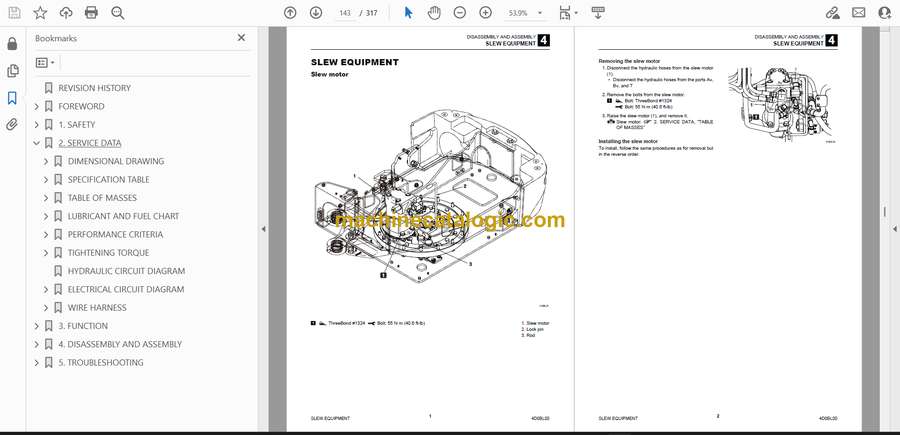
- SLEW EQUIPMENT
- Slew motor
- Removing the slew motor
- Installing the slew motor
- Slew bearing
- Removing the slew bearing
- Installing the slew bearing
- Swivel joint
- Removing the swivel joint
- Installing the swivel joint
- UPPER FRAME
- Upper frame
- Removing the upper frame
- Installing the upper frame
- Covers
- Removing the covers
- Installing the covers
- Canopy
- OPERATING DEVICE
- Construction diagram
- Control levers
- Lever stand
- Pilot valve (Left)
- Pilot valve (Right)
- Hydraulic piping
- Type A (ISO)
- Table of Connections
- Type A ↔ Type G
- Table of Connections
- Disassembly and assembly
- Removal and installation of the accumulator
- WORK EQUIPMENT
- Construction diagram
- Hoe attachment
- Boom swing
- Blade
- Spanner cylinder
- Disassembly and assembly
- Hoe attachment
- Release of residual pressure
- Blade
- Spanner cylinder
- Attaching the attachments
- HYDRAULIC TANK
- Removing the hydraulic tank
- Installing the hydraulic tank
- HYDRAULIC PUMP (GEAR)
- Construction
- Disassembly and assembly
- General precautions
- Disassembly
- Assembly
- Inspection and adjustment
- Checking the parts
- Test operation
- Measuring the discharge volume
- CONTROL VALVE
- Construction
- Disassembly and assembly
- General precautions
- Disassembly
- Assembly
- Inspection and adjustments
- Checking the parts
- Main relief valve pressure adjustment
- SOLENOID VALVE (LEVER LOCK)
- Construction
- Disassembly
- Solenoid valve
- Relief valve
- Check valve
- Assembly
- Inspection and adjustment
- SELECTOR VALVE
- Construction
- Disassembly and Assembly
- Inspection and adjustment
- CYLINDER
- Construction
- Boom cylinder
- Arm cylinder
- Bucket cylinder
- Dozer blade cylinder
- Swing cylinder
- Spanner cylinder
- Disassembly and assembly
- Special tools
- Disassembly
- Assembly
- Inspection and adjustment
- Inspection after disassembly
- Inspection after assembly
- TRAVEL MOTOR
- Construction
- Hydraulic motor
- Reduction gears
- Valves
- Disassembly and assembly
- General precautions
- Assembly
- Inspection and adjustments
- SLEW MOTOR
- Construction
- Disassembly and assembly
- Inspection and adjustments
- SWIVEL JOINT
- Construction
- Disassembly and Assembly
- Inspection and adjustment
- Inspection procedures and remedial actions
- Use limit for parts
- Inspection after assembly
- 5. TROUBLESHOOTING
- ABOUT THE TROUBLESHOOTING SECTION
- Notes on troubleshooting and servicing
- OVERALL MACHINE
- No operation is possible.
- All systems working, but insufficient force.
- Boom, bucket, slew and arm fail to move or are too slow.
- TRAVELING
- No travel is possible.
- Right or left travel is impossible.
- Right or left travel speed decelerates, causing the machine to veer to one side.
- 2nd-speed travel is not possible.
- SLEWING
- No slewing is possible.
- Slew right or left is not possible.
- Slewing is slow or lacks force.
- The machine slews, but overruns a lot when slewing stops, or slewing cannot be stopped.
- When stopped on a slope, the upperstructure cannot maintain its posture.
- BOOM
- The boom cylinder does not move
- Boom cylinder operation is slow or lacks force.
- When the boom control lever is pulled slowly, the boom drops at first
- Spontaneous drop of the boom cylinder is too large.
- ARM
- Arm cylinder does not move.
- Arm cylinder operation is slow or lacks force.
- Spontaneous drop of the arm is too large.
- BUCKET
- Bucket cylinder does not move or lacks force.
- Spontaneous drop of the bucket is too large.
- BOOM SWING
- Swing cylinder does not move.
- DOZER BLADE
- Dozer blade cylinder does not move or lacks force.
- The spontaneous drop of the dozer blade is too large, or the dozer blade cannot support the machine.
- AUXILIARY HYDRAULICS (1ST)
- Prescribed pressure is not supplied to the auxiliary lines.
- SPANNER
- Spanner cylinder does not move or lacks force.
- GEAR PUMP
- CONTROL VALVE
- PILOT VALVE
- SOLENOID VALVE
- CYLINDERS
- TRAVEL MOTOR
- Hydraulic motor
- 2nd-speed control
- Parking brake
- SLEW MOTOR
- Hydraulic motor, brake valve
- SWIVEL JOINT
Takeuchi


