Takeuchi TB225 Mini Excavator Workshop Manual (CD8E009) (SN 122600003-)
Out on utility digs, landscaping jobs, or tight urban sites, the TB225 spends its life in dirt, mud, and concrete rubble—so things wear, loosen, and occasionally break. This workshop manual is what I’d pull up when I need a step‑by‑step sequence to strip, inspect, and correctly refit a major component, not just guess from experience. For example, if the boom starts drifting or feels spongy, I’d use this to trace the fault through the hydraulic circuit, verify clearances, and then safely reinstall and test the cylinder or valve once repairs are done.
Applications & Use Cases
- Plan a full undercarriage service, from track removal to final tension and alignment checks.
- Trace a hydraulic leak or weak function and isolate whether it’s a hose, seal, or control component.
- Follow a structured sequence to remove and refit the boom, arm, or blade without stressing pins or bushings.
- Inspect and verify slew system play or noise, then reassemble with correct backlash and locking checks.
- Support engine‑bay work by routing hoses, looms, and guards back exactly as designed after repairs.
FAQ
Q: Can I keep this manual open on a tablet in the field?
A: Yes, it works well on a tablet; I’d still screenshot or bookmark key procedures before heading out with poor reception.
Q: Is it worth printing parts of this manual?
A: I usually print the pages for the job I’m doing, slip them in a plastic sleeve, and mark notes or measurements as I go.
Safety Note
Always lock out, support, and depressurize the TB225 before loosening any structural or hydraulic components.
Takeuchi TB225 Mini Excavator Index:
- REVISION HISTORY
- FOREWORD
- Directional terms: front, rear, left, right
- Machine serial number
- Symbols used in this manual
- Manual structure
- 1. SAFETY
- SAFETY ALERT SYMBOL
- SAFETY PRECAUTIONS
- Observe all safety rules
- Wear safe clothing and protective gear
- Install an extinguisher and a first aid kit
- Lockout/Tagout (LOTO)
- Use the correct tools
- Regularly replace the safety-critical parts
- Explosionproof lighting
- Prohibit access by unauthorized persons
- Prepare the work area
- When the canopy is tilted up
- Keep the machine clean
- Stop the engine before performing maintenance
- Keep clear of the moving fan and belt
- When working under the machine
- When working on the machine
- Securing the working equipment
- Secure the engine hood and guard when they are open
- Place heavy components in a stable position
- Caution when filling with fuel or oil
- Handling of hoses
- Be careful with hot and pressurized components
- Handling of radiator
- Be careful with oils under pressure
- Release the residual pressure from the hydraulic system before performing maintenance
- Be careful with grease under pressure
- Handling of the accumulator
- Disconnect the battery
- Use caution when handling batteries
- Have a service agent repair welding cracks or other damage
- Checks after maintenance
- Disposing of wastes
- CAUTIONS WHEN WORKING
- Before starting work
- When disassembling or assembling
- When removing/installing the hydraulic unit
- When connecting/disconnecting the hoses or pipes
- Handling of seals
- Pressure adjustment for hydraulic devices
- 2. SERVICE DATA
- DIMENSIONAL DRAWING
- Machine dimensions
- Operating range
- SPECIFICATION TABLES
- Performance
- Dimensions of completed machine
- Dimensions of base machine
- Engine
- Hydraulic system
- Operating device
- Slew equipment
- Lower machinery
- Working equipment
- Working dimensions
- Main structure
- Hydraulic cylinder
- Digging force
- Dozer blade
- TABLE OF MASSES
- Upper structure
- Lower structure
- Attachments
- LUBRICANT AND FUEL CHART
- PERFORMANCE CRITERIA
- Standard values table
- Hydraulic pump assignment table
- Hydraulic pump No. P1
- Hydraulic pump No. P2
- Hydraulic pump No. P3
- Hydraulic pump No. P4
- Methods for inspecting performance
- 1. Engine speed
- 2. Hydraulic pressure
- 3. Cylinder operating speed
- 4. Slew speed two rotations
- 5. Overrun when slewing stops
- 6. Natural travel drop (Over 5 min)
- 7. Natural slew drop (Over 5 min)
- 8. Travel speed (10 m (32.8 ft))
- 9. Travel speed (5 revolutions)
- 10. Straight-ahead traveling (10 m (32.8 ft))
- 11. Straight travel function check
- 12. Natural cylinder drop
- 13. Backlash
- 14. Lever play
- 15. Lever operating force
- 16. Blade levelness
- 17. Blade height
- 18. Service flow rate measurement method
- 19. Slew bearing play
- TIGHTENING TORQUE
- Hydraulic hose
- Bite-type pipe fitting for steel pipe
- Joint for piping
- Joint for piping (O-ring seal type)
- Bolts and nuts (JIS strength category 10.9)
- HYDRAULIC CIRCUIT DIAGRAM
- ELECTRICAL CIRCUIT DIAGRAM
- Symbols in electrical circuit diagram
- Wire color symbols
- Wire color table
- Wire types
- Schematic diagram
- 適用号機:122600003 to 122600038
- 適用号機:122600039 to 122600074
- 適用号機:122600075 to 122600117
- 適用号機:122600118 or later
- WIRE HARNESS
- Electrical wiring assembly
- Main unit harness
- 適用号機:122600003 to 122600074
- 適用号機:122600075 to 122600117
- 適用号機:122600118 or later
- Assembly of right control box
- Assembly of boom
- Wire harness
- Wire harness
- Engine cover assembly
- Assembly of canop
- Wire harness
- Wire harness
- HYDRAULIC DEVICE LAYOUT DIAGRAM
- 3. FUNCTION
- HYDRAULIC PUMP
- Constant horsepower control
- Power shift mode (reduced horsepower control by P3 pressure)
- Highland mode (reduced horsepower control by Pc pressure)
- CONTROL VALVE
- Overview
- Description of operation
- Bucket
- Boom
- P1 travel
- P1/P2 inlet
- P2 travel
- Arm
- Swing
- 1st service
- Slew
- Blade
- Span
- Communication valve
- PILOT VALVE (CONTROL LEVER)
- PILOT VALVE (SWING)
- PILOT VALVE (TRAVEL)
- PROPORTIONAL SOLENOID VALVE (1ST SERVICE)
- SOLENOID VALVE (LEVER LOCK, SPEED SHIFT TRAVEL)
- Solenoid switching/relief function
- When not energized
- When energized
- Check function
- SELECTOR VALVE
- CYLINDER (BOOM, ARM, SWING, BLADE)
- Function
- Function of each part
- Seal system components: Bushing (4), rod packing (5), dust seal (6)
- Piston assembly
- Operation
- TRAVEL MOTOR
- Reduction gear
- Function
- Description for operation
- Hydraulic motor
- Motor function
- Motor construction and operating principle
- 2-speed motor operating principle
- Hydraulic valve
- Counterbalance valve
- Automatic 1st speed valve
- Parking brake
- SLEW MOTOR
- Reduction gear
- Hydraulic motor
- Hydraulic valve
- Shockless relief valve
- Check valve
- Timer valve
- SWIVEL JOINT
- 4. DISASSEMBLY AND ASSEMBLY
- SERVICE STANDARD
- Carrier roller
- Track roller
- Sprocket
- Idler
- Pin to bushing clearance
- About replacement of pin and bushing
- DRIVE EQUIPMENT
- Engine
- Engine sub-assembly (cab)
- Radiator
- Construction diagram
- Removing the engine
- Installation of engine
- Hydraulic pump
- Construction diagram
- Removal of hydraulic pump
- Installation of hydraulic pump
- Precautions when starting the hydraulic pump
- Fuel tank
- Fuel tank sub-assembly
- Construction diagram
- Removal of fuel tank
- Installation of fuel tank
- Battery
- Construction diagram
- Removal of battery
- Installation of battery
- Air cleaner (double element specification)
- Engine control
- Construction diagram
- Adjustment method for actuator wire
- TRAVEL EQUIPMENT
- Track roller
- Carrier roller
- Front idler
- Grease cylinder assembly
- Travel motor
- Lower frame
- Crawler belt (rubber)
- Construction diagram
- Removal of rubber crawler
- Installation of rubber crawler
- Removal of carrier roller
- Installation of carrier roller
- Removal of track roller
- Installation of track roller
- Removal of idler and grease cylinder assembly
- Installation of idler and grease cylinder assembly
- Removal of travel motor
- Installation of travel motor
- SLEW EQIUPMENT
- Slew motor
- Construction diagram
- Removal of slew motor
- Installation of slew motor
- Slew bearing
- Construction diagram
- Removal of slew bearing
- Installation of slew bearing
- Swivel joint
- Construction diagram
- Removal of swivel joint
- Installation of swivel joint
- UPPER FRAME
- Upper frame
- Grease piping
- Construction diagram
- Removal of upper frame
- Installation of upper frame
- Cover (cab specification)
- Cover (canopy specification)
- Construction diagram
- Removal of cover
- Installation of cover
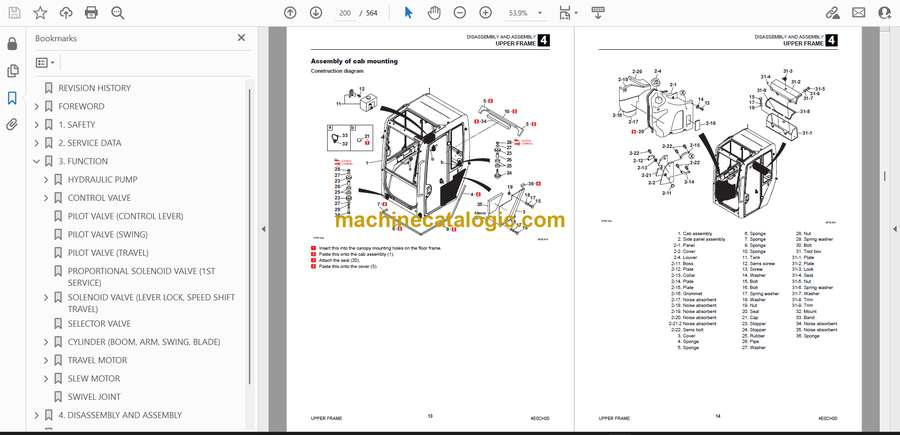
- Assembly of cab mounting
- Assembly of cab
- Assembly of canopy
- Assembly of floor frame (cab specification)
- Assembly of floor frame (canopy specification)
- Assembly of operator seat
- Assembly of radio
- Assembly of floor mat
- Assembly of floor mat
- Assembly of right side cab light
- Assembly of front guard
- Construction diagram
- Removal of cab
- Installation of cab
- Removal of canopy
- Installation of canopy
- Removal of glass
- Installation of glass
- CONTROL EQUIPMENT
- Construction diagram
- Travel lever
- Control lever piping
- Control lever piping
- Control lever piping
- Right control box
- Left control box
- Disassembly and assembly
- Removal and installation of the accumulator
- WORK EQUIPMENT
- Construction diagram
- Assembly of arm
- Assembly of bucket
- Assembly of boom
- Assembly of boom swing
- Assembly of blade
- Assembly of swing stopper
- Disassembly and assembly
- Removal and installation of the bucket
- Removal and installation of the bucket link
- Releasing residual pressure
- Removal and installation of the arm
- Removal and installation of the boom
- Removal and installation of the swing bracket
- Removal and installation of the blade
- HYDRAULIC OIL TANK
- Hydraulic oil tank
- Construction diagram
- Removal of hydraulic oil tank
- Installation of hydraulic oil tank
- Oil level inspection and replenishment of hydraulic oil tank
- Inspection
- Replenishment
- Method for bleeding air
- HYDRAULIC PUMP
- Construction diagram
- Disassembly and assembly
- Tools required for disassembly and assembly
- Disassembly
- Assembly
- Service standard
- CONTROL VALVE
- Construction diagram
- Disassembly and assembly
- Disassembly
- Inspection
- Assembly
- PILOT VALVE
- Construction
- Special tools
- Installation jig A
- Installation jig B
- Disassembly and Assembly
- Inspection and adjustment
- PILOT VALVE (SWING)
- Construction diagram
- Special jig
- Disassembly and assembly
- Inspection and adjustment
- PILOT VALVE (TRAVEL)
- Construction diagram
- Disassembly and Assembly
- General precautions
- Special Jigs
- Disassembly
- Assembly
- Inspection and adjustment
- PROPORTIONAL SOLENOID VALVE (1ST SERVICE)
- Construction
- Disassembly and assembly
- Inspection and adjustment
- SOLENOID VALVE (LEVER LOCK)
- Construction
- Disassembly
- Solenoid valve
- Relief valve
- Check valve
- Assembly
- Inspection and adjustment
- SELECTOR VALVE
- Construction
- Disassembly and Assembly
- Inspection and adjustment
- CYLINDER (BOOM, ARM, SWING, BLADE)
- Boom cylinder
- Boom cylinder (with emergency shutoff valve)
- Arm cylinder
- Arm cylinder (with emergency shutoff valve)
- Swing cylinder
- Blade cylinder
- Disassembly and assembly
- Service standard
- Inspection after assembly
- Tools required
- Special jig
- Disassembly
- Assembly
- BUCKET CYLINDER
- Construction diagram
- Disassembly and assembly
- Inspection after adjustment and disassembly
- Inspection after assembly
- Tools required
- Disassembly
- Assembly
- SPAN CYLINDER
- Construction diagram
- Disassembly and assembly
- Tools required
- Disassembly
- Assembly
- TRAVEL MOTOR
- Construction diagram
- Disassembly and assembly
- Tools required for disassembly and assembly
- Disassembly
- Hydraulic motor (disassembly)
- Assembly
- SLEW MOTOR
- Reduction gear
- Hydraulic motor
- Relief valve
- Timer valve
- Disassembly and assembly
- Tools required for disassembly and assembly
- Disassembly
- Assembly
- SWIVEL JOINT
- Construction
- Disassembly and Assembly
- Inspection and adjustment
- Inspection procedures and remedial actions
- Use limit for parts
- Inspection after assembly
- WIRE HARNESS
- MAIN UNIT HYDRAULIC PIPING & LOWER HYDRAULIC PIPING
- Main unit hydraulic piping
- Construction diagram
- Table of connections
- Lower hydraulic piping
- Construction diagram
- Table of connections
- 5. TROUBLESHOOTING
- TROUBLESHOOTING
- Notes on the malfunction diagnosis and repair
- GENERAL
- The engine does not start.
- 1. Did any error code occur?
- 2. Does the starter motor rotate?
- 3. Is there enough fuel?
- 4. Is the fuel filter clogged?
- The engine speed cannot be increased.
- 1. Did any error code occur?
- All the attachments and travel motors are inoperable.
- 1. Did any vehicle error code occur?
- 2. Is the hydraulic oil above the specified amount?
- 3. Is the pilot pressure within the standard value range?
- 4. Is the main pressure within the standard value range?
- All the attachments and travel motors are operable but are slow.
- 1. Does the engine speed reach the maximum?
- 2. Is the hydraulic oil above the specified amount?
- 3. Is abnormal sound coming from the hydraulic pump?
- 4. Is the pilot pressure within the standard value range?
- 5. Is the main pressure within the standard value range?
- TRAVEL
- The travel motors are inoperable (both left and right or one of them).
- 1. Do hydraulic devices other than the travel motor operate?
- 2. Is the discharge pressure from the pilot valve (for travel operation) normal?
- 3. Is the discharge pressure from the control valve (travel section) normal?
- 4. Is the discharge pressure from the swivel joint normal?
- The vehicle veers to one side with the left or right travel speed slowing down when it travels forward or backward.
- 1. Is the tension of the crawler normal?
- 2. Is any foreign matter trapped in the crawler?
- 3. Is the discharge pressure from the pilot valve (for travel operation) normal?
- 4. Is the discharge pressure from the control valve (travel section) normal?
- 5. Is the discharge pressure from the swivel joint normal?
- The travel speed cannot be changed.
- 1. Is the voltage applied to the solenoid valve (for variable travel speed)?
- 2. Is the variable travel speed pressure from the solenoid valve (for variable travel speed) normal?
- 3. Is the variable travel speed pressure (pilot pressure) from the swivel joint normal?
- SLEW
- The vehicle cannot slew.
- 1. Do hydraulic devices other than the slew operate?
- 2. Is the slew pressure within the standard value range?
- 3. Is the hydraulic piping that supplies the slew brake release pressure abnormal?
- 4. Does the slew bearing rotate?
- 5. Is the discharge pressure from the pilot valve (for slew operation) normal?
- 6. Is the discharge pressure from the control valve (slew section) normal?
- The vehicle cannot slew to the left or right.
- 1. Is the slew pressure within the standard value range?
- 2. Is the hydraulic piping that supplies the slew brake release pressure abnormal?
- 3. Is the discharge pressure from the pilot valve (for slew operation) normal?
- 4. Is the discharge pressure (main pressure) from the control valve (slew section) normal?
- 5. Is the slew relief valve normal?
- The vehicle can slew but is slow and less powerful.
- 1. Do hydraulic devices other than the slew operate normally?
- 2. Is the slew pressure below the standard value range?
- 3. Is the slew relief valve or relief valve seat abnormal?
- 4. Is the discharge pressure from the pilot valve (for slew operation) normal?
- 5. Is the discharge pressure from the control valve (slew section) normal?
- The slewing stop flow amount is large or the vehicle cannot stop.
- 1. Is the slew pressure below the standard value range?
- 2. Can the pilot valve (for slew operation) be in the neutral status?
- 3. Can the control valve (slew section) be in the neutral status?
- BOOM
- The boom cannot rise or drop.
- 1. Do hydraulic devices other than the boom operate?
- 2. Is the discharge pressure from the pilot valve (for boom operation) normal?
- 3. Is the discharge pressure from the control valve (boom section) normal?
- The boom can rise and drop but is slow and less powerful.
- 1. Do hydraulic devices other than the boom operate normally?
- 2. Is the discharge pressure from the pilot valve (for boom operation) normal?
- 3. Is the discharge pressure from the control valve (boom section) normal?
- 4. Is the boom cylinder internally leaking?
- The boom drops temporarily when the boom control lever is slowly pulled.
- 1. Is the boom cylinder internally leaking?
- The amount of boom natural drop is large.
- 1. Is the boom cylinder internally leaking?
- 2. Is the boom emergency shutoff valve internally leaking?
- ARM
- The arm cannot be pushed or pulled.
- 1. Do hydraulic devices other than the arm operate?
- 2. Is the discharge pressure from the pilot valve (for arm operation) normal?
- 3. Is the discharge pressure from the control valve (arm section) normal?
- The arm can be pushed and pulled but is slow and less powerful.
- 1. Do hydraulic devices other than the arm operate normally?
- 2. Is the discharge pressure from the pilot valve (for arm operation) normal?
- 3. Is the discharge pressure from the control valve (arm section) normal?
- The amount of arm natural drop is large.
- 1. Is the arm emergency shutoff valve internally leaking?
- BUCKET
- The bucket cannot dig or remove the ground.
- 1. Do hydraulic devices other than the bucket operate?
- 2. Is the discharge pressure from the pilot valve (for bucket operation) normal?
- 3. Is the discharge pressure from the control valve (bucket section) normal?
- The bucket can dig and remove the ground but is slow and less powerful.
- 1. Do hydraulic devices other than the bucket operate normally?
- 2. Is the discharge pressure from the pilot valve (for bucket operation) normal?
- 3. Is the discharge pressure from the control valve (bucket section) normal?
- The amount of bucket natural drop is large.
- 1. Is the hydraulic piping connected to the bucket cylinder failing, such as leaking?
- SWING
- The vehicle cannot swing.
- 1. Do hydraulic devices other than the swing operate?
- 2. Is the discharge pressure from the pilot valve (for swing operation) normal?
- 3. Is the discharge pressure from the control valve (swing section) normal?
- The vehicle can swing but is slow and less powerful.
- 1. Do hydraulic devices other than the swing operate normally?
- 2. Is the discharge pressure from the pilot valve (for bucket operation) normal?
- 3. Is the discharge pressure from the control valve (swing section) normal?
- The amount of swing natural drop is large.
- 1. Is the hydraulic piping connected to the swing cylinder failing, such as leaking?
- BLADE
- The blade does not rise or drop.
- 1. Do hydraulic devices other than the blade operate?
- 2. Is the linkage normal?
- 3. Is the discharge pressure from the control valve (blade section) normal?
- 4. Is the discharge pressure from the swivel joint normal?
- The blade can rise and drop but is slow and less powerful.
- 1. Do hydraulic devices other than the blade operate normally?
- 2. Is the linkage normal?
- 3. Is the discharge pressure (main pressure) from the control valve (blade section) normal?
- 4. Is the discharge pressure (main pressure) from the swivel joint normal?
- The amount of blade natural drop is large.
- 1. Is the hydraulic piping connected to the blade cylinder failing, such as leaking?
- SERVICE
- The attachment connected to the 1st service is inoperable.
- 1. Do hydraulic devices other than the 1st service operate?
- 2. Is the voltage applied to the proportional solenoid valve (for 1st service)?
- 3. Is the pressure on the 1st service A and B within the standard value range?
- 4. Is the discharge pressure from the proportional solenoid valve (for 1st service) normal?
- The attachment connected to the 2nd service is inoperable.
- 1. Do hydraulic devices other than the 2nd service operate?
- 2. Is the voltage applied to the solenoid valve (for 2nd service and 4th service switching)?
- 3. Is the voltage applied to the proportional solenoid valve (for 2nd service)?
- 4. Is the pressure on the 2nd service A and B within the standard value range?
- 5. Is the discharge pressure from the proportional solenoid valve (for 2nd service) normal?
- 6. Is the discharge pressure from the control valve (2nd service section) normal?
- The quick-hitch cannot be locked (3rd service).
- 1. Do hydraulic devices other than the quick-hitch operate?
- 2. Is the pressure on the 3rd service A normal?
- 3. Is the hydraulic piping connected to the 3rd service A failing?
- The quick-hitch cannot be unlocked (3rd service).
- 1. Do hydraulic devices other than the quick-hitch operate?
- 2. Is the pressure on the 3rd service B within the standard value range?
- 3. Is the voltage applied to the solenoid valve (for 3rd service)?
- 4. Is the discharge pressure from the solenoid valve (for 3rd service) normal?
- SPAN
- The span does not extend or retract.
- 1. Do hydraulic devices other than the span operate?
- 2. Is the linkage normal?
- 3. Is the discharge pressure from the control valve (span section) normal?
- 4. Is the discharge pressure from the swivel joint normal?
- HYDRAULIC PUMP
- PILOT VALVE (OPERATION LEVER, SWING)
- PILOT VALVE (TRAVEL)
- SOLENOID VALVE (LEVER LOCK)
- CYLINDER (BOOM, ARM, SWING, BLADE)
- Malfunction and remedy of hydraulic cylinder
- BUCKET CYLINDER
- SLEW MOTOR
- SWIVEL JOINT
- 6. OTHER
- MAINTENANCE SOFTWARE MANUAL
- CONTENTS
- 1. OVERVIEW
- 2. CONNECTION METHOD
- 2-1. Parts needed
- 2-2. Installation method
- 2-2-1. Installation of “PLUS+1 Service Tool”
- 2-2-2. Installation of maintenance tool driver
- 2-3. Connection to work machine and startup of maintenance software
- VEHICLE ERROR CODES
- Diagnostics procedures for malfunctions and failure
- Repair procedures
- How to check the detection ports
- TABLE OF VEHICLE ERROR CODES
Takeuchi


