Takeuchi TB23R Compact Excavator Workshop Manual (CD5E002) (SN 12300007-)
The TB23R is a small excavator that spends its life in tight spaces—landscaping, service trenching, around buildings and utilities. This workshop manual is what I’d pull out when I need a clear, step‑by‑step sequence to strip, inspect, and correctly refit major components so the machine goes back to work without comebacks. If, for example, the swing feels sloppy or a final drive starts leaking, this is the document that guides you through controlled teardown, measurement checks, and safe reassembly instead of guessing.
Applications & Use Cases
- Plan a full repair sequence before tearing into the boom, swing, or undercarriage so parts and tools are ready and downtime stays short.
- Trace hydraulic faults by following the recommended order of checks, helping you isolate a sticky valve or misrouted hose without chasing your tail.
- Inspect and verify wear limits on pins, bushings, and structural components during scheduled services.
- Align and reinstall travel and swing components so the machine tracks straight and turns smoothly after major work.
- Bleed and test hydraulic circuits after hose, cylinder, or pump replacement to avoid aeration and erratic movements.
FAQ
Q: Can I use this manual on a tablet in the field?
A: Yes, it’s practical to keep it on a tablet or laptop; you can zoom diagrams and search text, then print key pages for greasy jobs.
Q: Is this still useful if I’m only doing basic repairs?
A: Definitely; even for simple jobs it shows correct tightening order, inspection points, and final checks so you don’t miss something critical.
Safety Note
Always follow the manual’s support, lockout, and pressure‑relief steps before loosening any component on the TB23R.
Takeuchi TB23R Compact Excavator Index:
- TB23R
- FOREWORD
- I . GENERAL
- Safety precautions
- Cautions during disassembly and assembly
- Cautions during removal and installation of the hydraulic units
- Cautions during removal and installation of piping
- Handling of seals
- Tightening torques
- II . SPECIFICATIONS
- Names of components
- Dimensions
- Machine dimensions
- Operating ranges
- Specifications tables
- Specifications
- Specifications of devices
- Mass tables
- Recommended lubricants
- Servicing standards
- Travel system
- Working equipment
- Standards for judging performance
- Reference value table
- Methods for inspecting performance
- III . MACHINE CONFIGURATION
- Drive system
- Slew system
- Travel system
- Construction
- Disassembly and assembly
- Upper frame
- Construction
- Disassembly and assembly
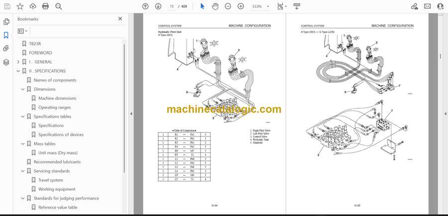
- Control system
- Construction
- Inspection and adjustment
- Attachments
- Construction
- Disassembly and assembly
- Hydraulic system
- Hydraulic circuit diagram
- Construction
- Disassembly and assembly
- Electrical system
- Electrical wiring diagram
- IV . HYDRAULIC UNITS
- Hydraulic pump
- Construction
- Operation
- Disassembly and assembly
- Inspection and adjustment
- Troubleshooting
- Control valve
- Construction
- Operation
- Disassembly and assembly
- Inspection and adjustment
- Troubleshooting
- Solenoid valve
- Construction
- Operation
- Disassembly and assembly
- Inspection and adjustment
- Troubleshooting
- Pilot valve
- Construction
- Operation
- Disassembly and assembly
- Inspection and adjustment
- Troubleshooting
- Cylinder
- Construction
- Operation
- Disassembly and assembly
- Inspection and adjustment
- Troubleshooting
- Travel motor
- Construction
- Operation
- Disassembly and assembly
- Inspection and adjustment
- Troubleshooting
- Slew motor
- Construction
- Operation
- Disassembly and assembly
- Inspection and adjustment
- Troubleshooting
- Swivel joint
- Construction
- Operation
- Disassembly and assembly
- Inspection and adjustment
- Troubleshooting
- V . TROUBLESHOOTING
- OVERALL MACHINE
- No operations can be done.
- All operations can be done, but there is no power.
- The boom, bucket, slew and arm do not move at all, or the speed is low.
- MACHINE TRAVEL
- The machine will not travel at all.
- Right or left travel is impossible.
- Speed drops in the left or right travel, causing the machine to travel in a curve.
- Machine won’t accelerate during travel.
- SLEWING
- No slewing can be done.
- Right or left slewing cannot be done.
- Slewing speed is low, or there is no power.
- The machine slews, but overrun when slewing stops is great, or it cannot be stopped.
- When stopped on a slope, the slewing body cannot maintain its posture after stopping.
- BOOM
- The boom cylinder doesn’t move.
- Boom cylinder operation is slow, or there is no power.
- When the boom operation lever is pulled gently, the boom drops temporarily.
- The amount of boom natural drop is great.
- ARM
- The arm cylinder doesn’t move.
- Arm cylinder operation is slow, or there is no power.
- The amount of arm natural drop is great.
- BUCKET
- The bucket cylinder doesn’t move, or there is no power.
- The amount of bucket natural drop is great.
- BOOM SWING
- The swing cylinder doesn’t move.
- DOZER BLADE
- The dozer blade cylinder doesn’t move, or there is no power.
- The amount of dozer blade natural drop is great or the dozer blade won’t hold the machine up.
- VI . ENGINE
- Cover
- History of Revision
- PREFACE
- SAFETY LABELS
- CONTENTS
- 1. General
- 1.1 Engine nomenclature
- 1.2 Specifications
- 1.3 Fuel oil, lubricating oil and cooling water
- 1.3.1 Fuel oil
- 1.3.2 Lubricating oil
- 1.3.3 Cooling water
- 1.4 Engine external views
- 1.5 Structural description
- 1.6 Exhaust gas emission regulation
- 1.6.1 The emission standard in USA
- 1.6.2 Engine identification
- 1.6.3 Guarantee conditions for the EPA emission standard
- 2. Inspection and adjustment
- 2.1 Periodic maintenance schedule
- 2.2 Periodic inspection and maintenance procedure
- 2.2.1 Check before daily operation
- 2.2.2 Inspection after initial 50 hours operation
- 2.2.3 Inspection every 50 hours
- 2.2.4 Inspection every 250 hours or 3 months
- 2.2.5 Inspection every 500 hours or 6 months
- 2.2.6 Inspection every 1,000 hours or one year
- 2.2.7 Inspection every 2000 hours or 2 years
- 2.3 Adjusting the no-load maximum or minimum speed
- 2.4 Sensor inspection
- 2.4.1 Oil pressure switch
- 2.4.2 Thermo switch
- 2.5 Water leak check in cooling water system
- 2.6 Radiator cap inspection
- 2.7 Thermostat inspection
- 2.8 Adjusting operation
- 2.9 Long storage
- 3. Troubleshooting
- 3.1 Preparation before troubleshooting
- 3.3 Troubleshooting by measuring compression pressure
- 4. Disassembly, inspection and reassembly of engines
- 4.1 Complete disassembly and reassembly
- 4.1.1 Introduction
- 4.1.2 Special service tools
- 4.1.3 Complete disassembly
- 4.1.4 Precautions before and during reassembly
- 4.1.5 Adjusting operation
- 4.2 Cylinder head: disassembly, inspection and reassembly
- 4.2.1 Components (2-valve cylinder head)
- 4.2.2 Disassembly procedure:
- 4.2.3 Reassembly procedure:
- 4.2.4 Servicing points
- 4.2.5 Parts inspection and measurement
- 4.2.6 Valve seat correction
- 4.2.7 Valve guide replacement
- 4.2.8 Valve stem seal replacement
- 4.3 Gear train and camshaft
- 4.3.1 Components
- 4.3.2 Disassembly procedure:
- 4.3.3 Reassembly procedure:
- 4.3.4 Servicing points
- 4.3.5 Parts inspection and measurement
- 4.3.6 Oil seal replacement
- 4.3.7 Camshaft bushing replacement
- 4.4 Cylinder block
- 4.4.1 Components
- 4.4.2 Disassembly procedure:
- 4.4.3 Reassembly procedure:
- 4.4.4 Servicing points
- 4.4.5 Parts inspection and measurement
- 4.4.6 Cylinder bore correction
- 4.4.7 Piston pin metal replacement
- 4.4.8 Oil seal replacement (Flywheel housing side)
- 5. Lubrication system
- 5.1 Lubrication system diagram
- 5.2 Trochoid pump components
- 5.3 Disassembly (Reverse the below procedure for reassembly)
- 5.4 Servicing Points
- 5.5 Parts inspection and measurement
- 5.5.1 Trochoid pump inspection and measurement
- 6. Cooling system
- 6.1 Cooling water System
- 6.2 Cooling water pump components
- 6.3 Disassembly (Reverse the below procedure for reassembly)
- 6.4 Servicing points
- 7. Fuel injection pump / Governor
- 7.1 Introduction
- 7.2 Fuel injection pump
- 7.2.1 Fuel system diagram
- 7.2.2 External view and components
- 7.2.3 Disassembly procedure:
- 7.2.4 Reassembly procedure
- 7.2.5 Confirmation and adjustment of fuel injection timing
- 7.2.6 Confirmation and adjustment of no-load maximum and minimum speed
- 8. The specifications of a starting motor and the characteristics
- 8.1 The specifications and the characteristics
- 8.1.1 Specifications
- 8.1.2 Characteristics
- 8.2 The structure of a starting motor and the wiring diagram
- 8.2.1 Structure
- 8.2.2 Wiring diagram of a starting motor
- 8.3 Performance
- 9. Alternator
- 9.1 20A Alternator
- 9.1.1 Specifications
- 9.1.2 Structure
- 9.1.3 Wiring diagram
- 9.1.4 Standard output characteristics
- 9.1.5 Inspection
- 9.2 40A Alternator
- 9.2.1 Components
- 9.2.2 Specifications
- 9.2.3 Wiring diagram
- 9.2.4 Standard output characteristics
- 9.2.5 Inspection
- 9.3 Troubleshooting
- 10. Electric wiring
- 10.1 Electric wiring diagram
- 10.1.1 Alternator
- 10.1.2 Starting motor
- 10.1.3 Current limiter
- 10.1.4 Section area and resistance of electric wire
- 11. Service standards
- 11.1 Engine tuning
- 11.2 Engine body
- 11.2.1 Cylinder head
- 11.2.2 Gear train and camshaft
- 11.2.3 Cylinder block
- 11.3 Lubricating oil system (Trochoid pump)
- 12. Tightening torque for bolts and nuts
- 12.1 Tightening torques for main bolts and nuts
- 12.2 Tightening torques for standard bolts and nuts
- Back cover
Takeuchi


