Takeuchi TB257FR Mini Excavator Workshop Manual (CJ4E013) (SN 158400007-)
On a TB257FR that spends its life trenching along foundations, working tight streets, or loading trucks in cramped yards, this workshop manual is what I’d keep open on the bench. It walks you through how to strip, inspect, and correctly put back together the major systems so the machine goes back to work without comebacks. If, for example, you’ve got a boom swing that’s drifting or a drive motor that feels weak, this manual gives you a step‑by‑step path to trace the fault, verify clearances or adjustments, and then reassemble and test everything safely.
Applications & Use Cases
- Isolate hydraulic issues by following structured teardown and reassembly sequences for key components.
- Inspect slew, boom, and undercarriage parts methodically so you don’t miss wear points or seals.
- Route hoses and harnesses correctly after repairs to avoid rubbing, pinching, or misalignment.
- Verify adjustments on controls and linkages after cab or pedal work before releasing the machine.
- Perform engine‑bay and cooling‑system reinstallation checks after major component removal.
FAQ
Q: Can I use this manual on a tablet in the field?
A: Yes, it works well on a tablet; you can zoom diagrams and keep it beside you while you test or adjust components.
Q: Is it worth printing sections of this manual?
A: Printing the procedures you’re doing that day is handy—you can mark torque steps, oil points, and inspection notes without risking your device.
Safety Note
Always lock out, support, and relieve system pressure exactly as described before you loosen or remove any component.
Takeuchi TB257FR Mini Excavator Index:
- REVISION HISTORY
- FOREWORD
- Directional terms: front, rear, left, right
- Machine serial number
- Symbols used in this manual
- Manual structure
- 1. SAFETY
- SAFETY ALERT SYMBOL
- SAFETY PRECAUTIONS
- Observe all safety rules
- Wear safe clothing and protective gear
- Install an extinguisher and a first aid kit
- Lockout/Tagout (LOTO)
- Use the correct tools
- Regularly replace the safety-critical parts
- Explosionproof lighting
- Prohibit access by unauthorized persons
- Prepare the work area
- When the canopy is tilted up
- Keep the machine clean
- Stop the engine before performing maintenance
- Keep clear of the moving fan and belt
- When working under the machine
- When working on the machine
- Securing the working equipment
- Secure the engine hood and guard when they are open
- Place heavy components in a stable position
- Caution when filling with fuel or oil
- Handling of hoses
- Be careful with hot and pressurized components
- Handling of radiator
- Be careful with oils under pressure
- Release the residual pressure from the hydraulic system before performing maintenance
- Be careful with grease under pressure
- Handling of the accumulator
- Disconnect the battery
- Use caution when handling batteries
- Have a service agent repair welding cracks or other damage
- Checks after maintenance
- Disposing of wastes
- CAUTIONS WHEN WORKING
- Before starting work
- When disassembling or assembling
- When removing/installing the hydraulic unit
- When connecting/disconnecting the hoses or pipes
- Handling of seals
- Pressure adjustment for hydraulic devices
- 2. SERVICE DATA
- DIMENSIONAL DRAWING
- Machine dimensions
- Operating range
- SPECIFICATION TABLES
- Performance
- Dimensions of completed machine
- Dimensions of base machine
- Engine
- Hydraulic system
- Operating device
- Instruments
- Instruments
- Switches
- Switches
- Slew equipment
- Lower machinery
- Working equipment
- Working dimensions
- Main structure
- Hydraulic cylinder
- Digging force
- Blade
- TABLE OF MASSES
- Upper structure
- Lower structure
- Attachments
- TABLE OF FUEL AND LUBRICANT
- Diesel fuel
- Lubricant
- Supply oil level
- PERFORMANCE EVALUATION STANDARD
- Table of standard values
- Table of hydraulic pump assignment
- Hydraulic pump No. P1
- Hydraulic pump No. P2
- Hydraulic pump No. P3
- Hydraulic pump No. P4
- Performance inspection guideline
- 1. Engine speed
- 2. Hydraulic pressure
- 3. Cylinder speed
- 4. Slew speed (2 turns)
- 5. Slewing stop flow rate
- 6. 5-minute natural travel drop
- 7. 5-minute natural slew drop
- 8. Travel speed (10 m (32.8 ft))
- 9. Idle rotation speed (5 rotations)
- 10. Straight-ahead travel (10 m (32.8 ft))
- 11. Straight-ahead travel function check
- 12. Amount of natural cylinder drop
- 13. Backlash
- 14. Blade levelness
- 15. Blade height
- 16. Service flow rate
- 17. Slew bearing play
- TIGHTENING TORQUE
- Hydraulic hose
- Bite-type pipe fitting for steel pipe
- Joint for piping
- Joint for piping (O-ring seal type)
- Bolts and nuts (JIS strength category 10.9)
- HYDRAULIC CIRCUIT DIAGRAM
- Serial No.: 158400007 to 158400761
- Serial No.: 158400762 or later
- 3rd service hard lock specification
- Serial No.: 158400007 to 158400761
- Serial No.: 158400762 or later
- ELECTRICAL CIRCUIT DIAGRAM
- Symbols in electrical circuit diagram
- Wire color symbols
- Wire color table
- Schematic diagram
- Serial No.: 158400007 to 158400012
- Serial No.: 158400013 to 158400607
- Serial No.: 158400608 or later
- HYDRAULIC DEVICE LAYOUT DIAGRAM
- 3. FUNCTION
- HYDRAULIC PUMP
- Overview
- Pump appearance and ports
- Main structure and functions
- Piston pump
- Operating principle
- CONTROL VALVE
- Overview
- Functions of control valve
- Control in neutral position
- Operation of control valve
- Straight-ahead travel function
- Arm confluence function
- Anti-drift valve
- Boom priority circuit
- Auto-idle (AI) signal
- 3rd service (quick-hitch)
- Operations of main sections
- Bucket
- Boom
- Travel right
- Arm
- 3rd service (quick-hitch)
- Communication valve
- PILOT VALVE (CONTROL LEVER)
- PILOT VALVE (BLADE)
- PILOT VALVE (TRAVEL)
- PROPORTIONAL SOLENOID VALVE (1ST SERVICE / 2ND SERVICE)
- EMERGENCY SHUTOFF VALVE
- Spool at the neutral position
- When hydraulic oil flows from the port A to the port B
- When hydraulic oil flows from the port B to the port A
- When an abnormally high pressure is generated in the boom cylinder
- EMERGENCY SHUTOFF VALVE
- Neutral (Positions maintained)
- Boom cylinder raising and arm cylinder dumping operations
- Boom cylinder lowering and arm cylinder excavator operations
- Relief valve operation (When an abnormal high pressure is produced in the cylinder)
- SOLENOID VALVE (3RD AUXILIARY LINE PIPING)
- SOLENOID VALVE (LEVER LOCK, SPEED SHIFT TRAVEL)
- Solenoid switching/relief function
- When not energized
- When energized
- Check function
- SOLENOID VALVE (3RD SERVICE HARD LOCK)
- SELECTOR VALVE
- REDUCING VALVE
- CYLINDER
- CYLINDER
- Functions of parts
- Rod cover assembly
- Seal system configuration: Bushing (4), buffer ring (6), rod packing (7), backup ring (8), dust seal (9)
- Piston assembly
- Operation
- Basic function
- Cushion function
- TRAVEL MOTOR
- Hydraulic motor
- Counter balance valve
- 2-speed mechanism
- 2nd speed control valve
- Swash plate
- Automatic 2-speed switching system
- Parking brake
- Reduction gears
- SLEW MOTOR
- Hydraulic motor
- Relief valve
- The 1st stage
- The 2nd stage
- Make-up valve
- Anti-rebound valve
- When the brake is actuated
- When the Motor Rebounds
- Parking brake
- Timer valve
- Reduction gears
- SWIVEL JOINT
- 4. DISASSEMBLY AND ASSEMBLY
- SERVICE STANDARD
- Carrier roller
- Track roller
- Sprocket
- Front idler
- Pin
- DRIVE EQUIPMENT
- Construction diagram
- Assembly of engine
- Engine assembly
- Radiator assembly
- Assembly of hydraulic pump
- Assembly of fuel tank
- Assembly of battery
- Disassembly and assembly
- Removal and installation of the engine
- Removal and installation of the hydraulic pump
- Bleeding air from the hydraulic pump
- Removal and installation of the fuel tank
- TRAVEL EQUIPMENT
- Construction diagram
- Assembly of track roller
- Assembly of carrier roller
- Assembly of front idler
- Assembly of grease cylinder
- Assembly of travel motor
- Assembly of lower frame
- Disassembly and assembly
- Removal of the rubber crawler
- Installation of the rubber crawler
- Removal and installation of the carrier roller
- Removal of the track roller
- Installation of the track roller
- Removal and installation of the front idler assembly
- Removal and installation of the travel motor
- SLEW EQIUPMENT
- Construction diagram
- Assembly of slew motor
- Assembly of slew bearing
- Assembly of swivel joint
- Disassembly and assembly
- Removal and installation of the slew motor
- Removal and installation of the slew bearing
- Removal and installation of the swivel joint
- UPPER FRAME
- Construction diagram
- Assembly of main unit
- Assembly of grease piping
- Assembly of cover
- Assembly of cab mounting
- Assembly of canopy mounting
- Assembly of floor frame
- Assembly of floor frame
- Assembly of operator seat
- Disassembly and assembly
- Tilting up and tilting down of the cab assembly (canopy assembly)
- Tilting up of the cab assembly (canopy assembly)
- Removal and installation of the main unit
- Removal and installation of the engine cover assembly
- Removal and installation of the cover assembly
- Removal and installation of the cab assembly
- Removal of glass
- Installation of glass
- Removal and installation of the canopy assembly
- CONTROL EQUIPMENT
- Construction diagram
- Assembly of control lever
- Assembly of blade control lever
- Assembly of pilot piping
- Assembly of right control box
- Assembly of right control box
- Assembly of left control box
- Assembly of pilot valve (right operation lever) bracket
- Assembly of pilot valve (right operation lever) bracket
- Assembly of pilot valve (left operation lever) bracket
- Disassembly and assembly
- Removal and installation of the accumulator
- WORK EQUIPMENT
- Construction diagram
- Assembly of bucket
- Assembly of arm
- Long arm assembly
- Assembly of boom
- Boom assembly
- Boom cylinder assembly
- Arm cylinder assembly
- Assembly of boom switch
- Assembly of offset
- Assembly of offset switch
- Assembly of blade
- Disassembly and assembly
- Removal and installation of the bucket
- Releasing residual pressure
- Removal and installation of the arm assembly
- Removal and installation of the boom assembly
- Removal and installation of the boom bracket
- Removal and installation of the blade
- Adjustment and inspection
- Adjustment of the boom switch and offset switch
- Inspection of the boom switch and offset switch
- Adjustment of the boom stopper
- HYDRAULIC OIL TANK
- Construction diagram
- Assembly of hydraulic oil tank
- Disassembly and assembly
- Removal and installation of the hydraulic oil tank
- Oil level inspection and replenishment of the hydraulic oil tank
- Method for bleeding air
- HYDRAULIC PUMP
- Construction diagram
- Disassembly
- Assembly
- Inspection and adjustments
- CONTROL VALVE
- Construction diagram
- Bucket section
- Boom section
- Right travel section
- P1/P2 inlet section
- Left travel section
- Offset section
- 1st service section
- Arm section
- Slew section
- Blade section
- 2nd service section
- 3rd service section
- T3/P3 section
- Disassembly
- Removal of relief valve assembly and anti-void valve
- Disassembly of each section (bucket, right travel, left travel, offset, 1st service, arm, slew, blade, and 2nd service)
- Disassembly of boom section
- Disassembly of P1/P2 inlet section
- Disassembly of 3rd service section
- Disassembly of T3/P3 section
- Removal of load check valve, poppets, etc.
- Disassembly of valve housing
- Cleaning of each part
- Inspection of each part
- Assembly
- Assembly of valve housing
- Assembly of section
- Assembly of each section (bucket, right travel, left travel, offset, 1st service, arm, slew, blade, and 2nd service)
- Assembly of boom section
- Assembly of P1/P2 inlet section
- Assembly of 3rd service section
- Assembly of T3/P3 section
- Assembly of load check valves, poppets, etc.
- Installation of relief valve assembly and anti-void valve
- Relief valve maintenance procedure
- PILOT VALVE (CONTROL LEVER)
- Construction
- Special tools
- Installation jig A
- Installation jig B
- Disassembly and Assembly
- Inspection and adjustment
- PILOT VALVE
- Construction diagram
- Special jig
- Disassembly and assembly
- Inspection and adjustment
- PILOT VALVE
- Construction diagram
- Disassembly and assembly
- Disassembly of pilot valve
- Assembly of pilot valve
- PROPORTIONAL CONTROL SOLENOID VALVE (1ST/2ND AUXILIARY LINE PIPING)
- Construction
- Disassembly and Assembly
- Inspection and adjustment
- EMERGENCY SHUTOFF VALVE
- SOLENOID VALVE (LEVER LOCK)
- Construction
- Disassembly
- Solenoid valve
- Relief valve
- Check valve
- Assembly
- Inspection and adjustment
- SOLENOID VALVE (3RD AUXILIARY LINE PIPING)
- Construction
- Disassembly and Assembly
- Inspection and adjustment
- SOLENOID VALVE (3RD SERVICE HARD LOCK)
- Construction diagram
- Disassembly and assembly
- Disassembly of solenoid valve
- Assembly of solenoid valve
- SOLENOID VALVE (BLADE FLOAT)
- Construction
- Disassembly and Assembly
- Inspection and adjustment
- SELECTOR VALVE
- Construction
- Disassembly and Assembly
- Inspection and adjustment
- CYLINDER
- Construction diagram
- Boom cylinder
- Offset cylinder
- Disassembly and assembly
- Tools to be used
- Jigs
- Removal of cylinder rod assembly
- Disassembly of cylinder rod assembly
- Disassembly of piston assembly
- Disassembly of rod cover assembly
- Disassembly of clevis part
- Assembly of clevis part
- Assembly of rod cover assembly
- Assembly of piston assembly
- Assembly of cylinder rod assembly
- Assembly
- Inspection items after disassembly
- Inspection after assembly
- Bleeding air
- CYLINDER
- Construction diagram
- Arm cylinder
- Bucket cylinder
- Blade cylinder
- Disassembly and assembly
- Disassembly
- Washing and storage
- Assembly
- Start-up operation
- TRAVEL MOTOR
- Construction diagram
- Hydraulic motor
- Reduction gears
- Counterbalance valve, 2nd-speed control valve, relief block assembly
- Disassembly and assembly
- Inspection and adjustment
- SLEW MOTOR
- Construction
- Special tools
- Oil seal press-fitting jig A
- Collar inserting jig B
- Disassembly and assembly
- Inspection and adjustments
- SWIVEL JOINT
- Construction
- Disassembly and Assembly
- Inspection and adjustment
- Inspection procedures and remedial actions
- Use limit for parts
- Inspection after assembly
- WIRE HARNESS
- Electrical wiring assembly
- Main unit wiring assembly
- Engine wiring assembly
- Floor wiring assembly
- Electrical wiring assembly
- Other wire harnesses
- Travel alarm assembly
- Cab light assembly
- Fuel tank assembly
- Cab assembly
- Air conditioner unit assembly
- Boom offset assembly
- Control box assembly
- Harness supplied with engine
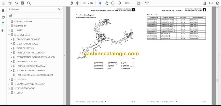
- MAIN UNIT HYDRAULIC PIPING & LOWER HYDRAULIC PIPING
- Construction diagram
- Main unit hydraulic piping assembly
- Construction diagram
- Lower hydraulic piping assembly
- 5. TROUBLESHOOTING
- TROUBLESHOOTING
- Notes on the malfunction diagnosis and repair
- GENERAL
- The engine does not start.
- 1. Did any error code occur?
- 2. Does the starter motor rotate?
- 3. Is there enough fuel?
- 4. Is the fuel filter clogged?
- The engine speed cannot be increased.
- 1. Did any error code occur?
- All the attachments and travel motors are inoperable.
- 1. Did any vehicle error code occur?
- 2. Is the hydraulic oil above the specified amount?
- 3. Is the pilot pressure within the standard value range?
- 4. Is the main pressure within the standard value range?
- All the attachments and travel motors are operable but are slow.
- 1. Does the engine speed reach the maximum?
- 2. Is the hydraulic oil above the specified amount?
- 3. Is abnormal sound coming from the hydraulic pump?
- 4. Is the pilot pressure within the standard value range?
- 5. Is the main pressure within the standard value range?
- ANTI-INTERFERENCE DEVICE
- The distance of the boom moving toward the cab (canopy) does not change even after switching the attachment anti-interference switch.
- 1. Did any vehicle error code occur?
- 2. Does the mode change to each AIPS mode?
- TRAVEL
- The travel motors are inoperable (both left and right or one of them).
- 1. Do hydraulic devices other than the travel motor operate?
- 2. Is the discharge pressure from the pilot valve (for travel operation) normal?
- 3. Is the discharge pressure from the control valve (travel section) normal?
- 4. Is the discharge pressure from the swivel joint normal?
- The vehicle veers to one side with the left or right travel speed slowing down when it travels forward or backward.
- 1. Is the tension of the crawler normal?
- 2. Is any foreign matter trapped in the crawler?
- 3. Is the discharge pressure from the pilot valve (for travel operation) normal?
- 4. Is the discharge pressure from the control valve (travel section) normal?
- 5. Is the discharge pressure from the swivel joint normal?
- The travel speed cannot be changed.
- 1. Is the voltage applied to the solenoid valve (for variable travel speed)?
- 2. Is the variable travel speed pressure from the solenoid valve (for variable travel speed) normal?
- 3. Is the variable travel speed pressure (pilot pressure) from the swivel joint normal?
- SLEW
- The vehicle cannot slew.
- 1. Do hydraulic devices other than the slew operate?
- 2. Is the slew pressure within the standard value range?
- 3. Is the hydraulic piping that supplies the slew brake release pressure abnormal?
- 4. Does the slew bearing rotate?
- 5. Is the discharge pressure from the pilot valve (for slew operation) normal?
- 6. Is the discharge pressure from the control valve (slew section) normal?
- The vehicle cannot slew to the left or right.
- 1. Is the slew pressure within the standard value range?
- 2. Is the hydraulic piping that supplies the slew brake release pressure abnormal?
- 3. Is the discharge pressure from the pilot valve (for slew operation) normal?
- 4. Is the discharge pressure (main pressure) from the control valve (slew section) normal?
- 5. Is the slew relief valve normal?
- The vehicle can slew but is slow and less powerful.
- 1. Do hydraulic devices other than the slew operate normally?
- 2. Is the slew pressure below the standard value range?
- 3. Is the slew relief valve or relief valve seat abnormal?
- 4. Is the discharge pressure from the pilot valve (for slew operation) normal?
- 5. Is the discharge pressure from the control valve (slew section) normal?
- The slewing stop flow amount is large or the vehicle cannot stop.
- 1. Is the slew pressure below the standard value range?
- 2. Can the pilot valve (for slew operation) be in the neutral status?
- 3. Can the control valve (slew section) be in the neutral status?
- BOOM
- The boom cannot rise or drop.
- 1. Do hydraulic devices other than the boom operate?
- 2. Is the discharge pressure from the pilot valve (for boom operation) normal?
- 3. Is the discharge pressure from the control valve (boom section) normal?
- The boom can rise and drop but is slow and less powerful.
- 1. Do hydraulic devices other than the boom operate normally?
- 2. Is the discharge pressure from the pilot valve (for boom operation) normal?
- 3. Is the discharge pressure from the control valve (boom section) normal?
- 4. Is the boom cylinder internally leaking?
- The boom drops temporarily when the boom control lever is slowly pulled.
- 1. Is the boom cylinder internally leaking?
- The amount of boom natural drop is large.
- 1. Is the boom cylinder internally leaking?
- 2. Is the boom emergency shutoff valve internally leaking?
- ARM
- The arm cannot be pushed or pulled.
- 1. Do hydraulic devices other than the arm operate?
- 2. Is the discharge pressure from the pilot valve (for arm operation) normal?
- 3. Is the discharge pressure from the control valve (arm section) normal?
- The arm can be pushed and pulled but is slow and less powerful.
- 1. Do hydraulic devices other than the arm operate normally?
- 2. Is the discharge pressure from the pilot valve (for arm operation) normal?
- 3. Is the discharge pressure from the control valve (arm section) normal?
- The amount of arm natural drop is large.
- 1. Is the arm emergency shutoff valve internally leaking?
- BUCKET
- The bucket cannot dig or remove the ground.
- 1. Do hydraulic devices other than the bucket operate?
- 2. Is the discharge pressure from the pilot valve (for bucket operation) normal?
- 3. Is the discharge pressure from the control valve (bucket section) normal?
- The bucket can dig and remove the ground but is slow and less powerful.
- 1. Do hydraulic devices other than the bucket operate normally?
- 2. Is the discharge pressure from the pilot valve (for bucket operation) normal?
- 3. Is the discharge pressure from the control valve (bucket section) normal?
- The amount of bucket natural drop is large.
- 1. Is the hydraulic piping connected to the bucket cylinder failing, such as leaking?
- ADJUSTER (TWO-PIECE BOOM)
- The adjuster cannot rise or drop.
- 1. Do hydraulic devices other than the adjuster operate?
- 2. Is the discharge pressure from the pilot valve (for adjuster operation) normal?
- 3. Is the discharge pressure from the control valve (adjuster section) normal?
- The adjuster can rise and drop but is slow and less powerful.
- 1. Do hydraulic devices other than the adjuster operate normally?
- 2. Is the discharge pressure from the pilot valve (for adjuster operation) normal?
- 3. Is the discharge pressure from the control valve (adjuster section) normal?
- The amount of adjuster natural drop is large.
- 1. Is the adjuster emergency shutoff valve internally leaking?
- BLADE
- The blade does not rise or drop.
- 1. Do hydraulic devices other than the blade operate?
- 2. Is the discharge pressure from the pilot valve (for blade operation) normal?
- 3. Is the discharge pressure from the control valve (blade section) normal?
- 4. Is the discharge pressure from the swivel joint normal?
- The blade can rise and drop but is slow and less powerful.
- 1. Do hydraulic devices other than the blade operate normally?
- 2. Is the discharge pressure from the pilot valve (for blade operation) normal?
- 3. Is the discharge pressure (main pressure) from the control valve (blade section) normal?
- 4. Is the discharge pressure (main pressure) from the swivel joint normal?
- The amount of blade natural drop is large.
- 1. Is the hydraulic piping connected to the blade cylinder failing, such as leaking?
- SERVICE
- The attachment connected to the 1st service is inoperable.
- 1. Do hydraulic devices other than the 1st service operate?
- 2. Is the voltage applied to the proportional solenoid valve (for 1st service)?
- 3. Is the pressure on the 1st service A and B within the standard value range?
- 4. Is the discharge pressure from the proportional solenoid valve (for 1st service) normal?
- The attachment connected to the 2nd service is inoperable.
- 1. Do hydraulic devices other than the 2nd service operate?
- 2. Is the voltage applied to the solenoid valve (for 2nd service and 4th service switching)?
- 3. Is the voltage applied to the proportional solenoid valve (for 2nd service)?
- 4. Is the pressure on the 2nd service A and B within the standard value range?
- 5. Is the discharge pressure from the proportional solenoid valve (for 2nd service) normal?
- 6. Is the discharge pressure from the control valve (2nd service section) normal?
- The quick-hitch cannot be locked (3rd service).
- 1. Do hydraulic devices other than the quick-hitch operate?
- 2. Is the pressure on the 3rd service A normal?
- 3. Is the hydraulic piping connected to the 3rd service A failing?
- The quick-hitch cannot be unlocked (3rd service).
- 1. Do hydraulic devices other than the quick-hitch operate?
- 2. Is the pressure on the 3rd service B within the standard value range?
- 3. Is the voltage applied to the solenoid valve (for 3rd service)?
- 4. Is the discharge pressure from the solenoid valve (for 3rd service) normal?
- HYDRAULIC PUMP
- CONTROL VALVE
- 1. Control valve in general
- 2. Relief valve
- 3. Hydraulic control in general
- PILOT VALVE
- PILOT VALVE
- PILOT VALVE
- SOLENOID VALVE (LEVER LOCK)
- SOLENOID VALVE (3RD SERVICE)
- CYLINDER
- Troubleshooting problems with the cylinder
- TRAVEL MOTOR
- Hydraulic motor
- 2nd-speed control
- Parking brake
- SLEW MOTOR
- Hydraulic motor, brake valve
- Parking brake
- 6. OTHER
- MAINTENANCE SOFTWARE MANUAL
- CONTENTS
- 1. OVERVIEW
- 2. CONNECTION METHOD
- 2-1. Parts needed
- 2-2. Installation method
- 2-2-1. Installation of “PLUS+1 Service Tool”
- 2-2-2. Installation of maintenance tool driver
- 2-3. Connection to work machine and startup of maintenance software
- AIR CONDITIONER
- Construction diagram
- Assembly of compressor
- Assembly of condenser
- Assembly of air conditioner unit
- Disassembly and assembly
- Removal and installation of the compressor
- Removal and installation of the condenser
- Removal and installation of the receiver dryer
- Removal and installation of the air conditioner unit
- AIR CONDITIONER SYSTEM
- Overview of System Operation
- Truck and Heavy Equipment Systems
- Air Conditioner—System Operation
- Heater System Operation
- Environmental Effects on System Operation
- Chapter Review
- Inspection and Maintenance without gauges
- Discussion of Inspection & Maintenance Survey Results
- Visual Inspection – System Off
- Electrical System Inspection
- Performance Inspection – Engine Running
- Heater System Inspection
- Preventive Maintenance Worksheet
- Chapter Review
- Troubleshooting & Service Procedures
- Troubleshooting Overview
- The Key–Understanding System Function
- A Troubleshooting Example
- Manifold Gauge Set Installation
- Troubleshooting by Manifold Gauge Set Readings
- Review of Frequent Problem Areas
- Conclusion
- Electrical wiring diagram
- TABLE OF VEHICLE ERROR CODES
- TABLE OF ENGINE ERROR CODES
Takeuchi


