Takeuchi TL240 Track Loader Workshop Manual (CU2E003) (SN 224000001_)
The TL240 spends its life in mud, gravel, and demolition debris, so when something’s off, you need a clear, step‑by‑step path, not guesswork. This Takeuchi TL240 Track Loader Workshop Manual is what I’d use to walk through a repair in order—strip, inspect, measure, reassemble, and test—without missing the small checks that prevent repeat failures. For example, if a track drive is running hot or noisy, this is the guide I’d follow to trace the fault, pull the components in the right sequence, and reinstall everything with proper alignment and final function checks.
Applications & Use Cases
- Planning a major teardown of the undercarriage, drive motor, or loader linkage with a clear disassembly/reassembly order.
- Tracing hydraulic issues by following the recommended sequences to isolate leaks, weak functions, or contamination.
- Verifying wear limits during routine inspections so you know when to replace instead of just tightening or greasing.
- Guiding safe reinstallation of pumps, valves, and cylinders, including bleed and test steps before putting the machine back to work.
- Supporting field repairs, using printed pages to double‑check torque patterns and adjustment steps away from the shop.
FAQ
Q: Can I use this manual on a tablet in the field?
A: Yes, it works well digitally; you can zoom diagrams and use search to jump to the procedure you’re working on.
Q: Is it worth printing sections of this manual?
A: Definitely—most techs print the relevant procedures so they can mark notes, keep greasy hands off the device, and tape pages right to the machine.
Safety Note
Always lock out, support, and relieve system pressures exactly as described before you loosen or remove any component.
📘 Show Index
Takeuchi TL240 Track Loader Index:
- SAFETY
- Safety alert symbol
- Safety precautions
- Cautions when working
- SERVICE DATA
- Dimensional drawing
- Specifications tables
- Lubricant and Fuel chart
- Performance criteria
- Tightening torque
- Hydraulic circuit diagram
- Electrical wiring diagram
- Wire harness diagram
- FUNCTION
- HST pump
- Gear pump
- Control valve
- Sub valve
- Pilot valve
- Proportional control solenoid valve
- Cylinders
- Travel motor
- Proportional control equipment
- Air conditioner system
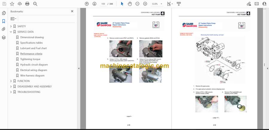
- DISASSEMBLY AND ASSEMBLY
- Service standards
- Drive system
- Travel system
- Frame
- Control system
- Attachments
- Hydraulic tank
- HST pump
- Gear pump
- Gear pump (High flow)
- Control valve
- Control valve (High flow)
- Sub valve
- Pilot valve
- Proportional control solenoid valve
- Cylinders
- Travel motor
- TROUBLESHOOTING
- Overall machine
- No operation is possible.
- All systems working, but insufficient power.
- Lift arm and bucket fail to move or are too slow.
- Traveling
- Traveling fails.
- Right or left travel speed decelerates and the machine veers to one side.
- Operating temperature of the travel system is too high.
- 2nd speed travel is not possible.
- Lift arm
- Arm cylinder fails.
- Arm cylinder is slow or the power is insufficient.
- When the control lever is pulled slowly, the lift arm drops once.
- Spontaneous drop of the lift arm is too large.
- Bucket
- Bucket cylinder fails to move.
- Bucket cylinder is slow or the power is insufficient.
- Spontaneous drop of the bucket is too large.
- HST pump
- Gear pump
- Control valve
- SUB valve
- Pilot valve
- Proportional control solenoid valve
- Cylinders
- Travel motor
- Air conditioner
Takeuchi


