Takeuchi TV1140 Hydraulic Excavator Workshop Manual (CN3E007) (SN 514400002-)
On a TV1140 that spends its life loading trucks, trenching, and working in muddy sites, this workshop manual is what I’d keep open any time I’m deep into the hydraulics or structure. It walks you through how to strip, inspect, and correctly reinstall the major components so the machine goes back to work without leaks, strange noises, or tracking issues. For example, if the boom starts drifting down or a travel motor feels weak, this is the guide I’d use to trace the fault, verify clearances, and reassemble everything in the right order.
Applications & Use Cases
- Planning a major repair on the boom, arm, or undercarriage so parts come off and go back on in a controlled sequence.
- Tracing hydraulic problems like slow functions or drifting cylinders by following a logical inspection path.
- Verifying reassembly of pumps, motors, and valve groups to avoid misaligned couplings or pinched seals.
- Checking wear points during scheduled services so you catch cracks, play, or leakage before they become failures.
- Guiding new technicians on correct torque habits, routing of hoses, and final function checks after a repair.
FAQ
Q: Can I use this manual on a tablet in the field?
A: Yes, it’s practical to keep a digital copy on a tablet so you can zoom diagrams and search procedures right at the machine.
Q: Is it worth printing sections of this manual?
A: Printing the pages for the job you’re doing works well; you can mark them up, keep them near the machine, and not worry about grease on your device.
Safety Note
Always support raised components securely and bleed any stored hydraulic pressure before loosening lines or fasteners.
Takeuchi TV1140 Hydraulic Excavator Index:
- REVISION HISTORY
- FOREWORD
- Directional terms: front, rear, left, right
- Machine serial number
- Symbols used in this manual
- Manual structure
- 1 SAFETY
- SAFETY ALERT SYMBOL
- SAFETY PRECAUTIONS
- Observe all safety rules
- Wear safe clothing and protective gear
- Install an extinguisher and a first aid kit
- Lockout/Tagout (LOTO)
- Use the correct tools
- Regularly replace the safety-critical parts
- Explosionproof lighting
- Prohibit access by unauthorized persons
- Prepare the work area
- When the canopy is tilted up
- Keep the machine clean
- Stop the engine before performing maintenance
- Keep clear of the moving fan and belt
- When working under the machine
- When working on the machine
- Securing the working equipment
- Secure the engine hood and guard when they are open
- Place heavy components in a stable position
- Caution when filling with fuel or oil
- Handling of hoses
- Be careful with hot and pressurized components
- Handling of radiator
- Be careful with oils under pressure
- Release the residual pressure from the hydraulic system before performing maintenance
- Be careful with grease under pressure
- Handling of the accumulator
- Disconnect the battery
- Use caution when handling batteries
- Have a service agent repair welding cracks or other damage
- Checks after maintenance
- Disposing of wastes
- CAUTIONS WHEN WORKING
- Before starting work
- When disassembling or assembling
- When removing/installing the hydraulic unit
- When connecting/disconnecting the hoses or pipes
- Handling of seals
- Pressure adjustment for hydraulic devices
- 2 SERVICE DATA
- DIMENSIONAL DRAWING
- SPECIFICATION TABLES
- Performance
- Dimensions of completed machine
- Dimensions of base machine
- Engine
- Hydraulic system
- Operating device
- Slew equipment
- Lower machinery
- Working equipment
- Working dimensions (standard arm)
- Main structure
- Hydraulic cylinder
- Digging force
- Dozer blade
- TABLE OF MASSES
- LUBRICANT AND FUEL CHART
- PERFORMANCE CRITERIA
- Standard values table
- Hydraulic pump assignment table
- Pump P1
- Pump P2
- Pump P3
- Pump Pr
- Methods for inspecting performance
- Hydraulic oil pressure (Boom, arm)
- Hydraulic oil pressure (Dozer blade)
- Hydraulic oil pressure (Slew)
- Hydraulic oil pressure (Pilot pressure)
- Travel speed (5 revs.)
- Travel speed (10 m)
- Straight-ahead traveling
- Natural travel drop
- Slew time
- Overrun when slewing stops
- Natural slew drop
- Boom cylinder speed
- Arm cylinder speed
- Bucket cylinder speed
- Dozer blade cylinder speed
- Swing cylinder speed
- Natural cylinder drop
- Swing
- Lever play
- Backlash
- Slew bearing play
- Track tension
- TIGHTENING TORQUE
- Hydraulic hose
- Bite-type pipe fitting for steel pipe
- Joint for piping
- Joint for piping (O-ring seal type)
- Bolts and nuts (JIS strength category 10.9)
- Hydraulic circuit diagram
- ELECTRICAL CIRCUIT DIAGRAM
- WIRE HARNESS DIAGRAM
- 3 FUNCTION
- Hydraulic pump (Main)
- HYDRAULIC PUMP (SUB)
- CONTROL VALVE
- Pilot valve (control lever)
- Pilot valve (swing)
- Pilot valve (blade)
- PILOT VALVE (TRAVEL)
- PROPORTIONAL SOLENOID VALVE (1ST SERVICE / 2ND SERVICE)
- EMERGENCY SHUTOFF VALVE
- SOLENOID VALVE
- SHOCKLESS VALVE
- CYLINDERS
- TRAVEL MOTOR
- Slew motor
- SWIVEL JOINT
- 4 DISASSEMBLY AND ASSEMBLY
- SERVICE STANDARDS
- DRIVE SYSTEM
- TRAVEL SYSTEM
- Removing the crawler
- Installing the crawler
- Removing a steel crawler or segmented rubber crawler
- Installing a steel crawler or segmented rubber crawler
- Attaching/removing a segmented rubber crawler
- Replacing the crawler
- Removing the carrier roller
- Installing the carrier roller
- Removing the track roller
- Installing the track roller
- Removing the idler and track adjuster
- Installing the idler and track adjuster
- Removing the travel motor
- Installing the travel motor
- SLEW EQUIPMENT
- UPPER FRAME
- OPERATING DEVICE
- ATTACHMENTS
- HYDRAULIC TANK
- HYDRAULIC PUMP (MAIN)
- HYDRAULIC PUMP (SUB)
- CONTROL VALVE
- Pilot valve
- Pilot valve (swing, blade)
- Pilot valve (travel)
- PROPORTIONAL CONTROL SOLENOID VALVE
- EMERGENCY SHUTOFF VALVE
- SOLENOID VALVE (DUAL-SECTION)
- Construction
- Disassembly and assembly
- Inspection and adjustments
- SHOCKLESS VALVE
- Construction
- Disassembly and assembly
- Inspection and adjustments
- CYLINDERS
- TRAVEL MOTOR
- SLEW MOTOR
- Construction
- Hydraulic motor
- Reduction gears
- Brake valve
- Special tools
- Disassembly and assembly
- Inspection and adjustments
- SWIVEL JOINT
- Construction
- Disassembly and Assembly
- Inspection and adjustment
- Inspection procedures and remedial actions
- Use limit for parts
- Inspection after assembly
- 5 TROUBLESHOOTING
- Notes on troubleshooting and servicing
- OVERALL MACHINE
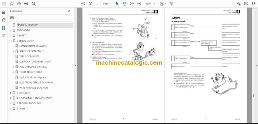
- TRAVELING
- SLEWING
- BOOM
- ARM
- BUCKET
- BOOM SWING
- BLADE
- AUXILIARY HYDRAULICS
- PISTON PUMP
- Gear pump
- Control valve
- Pilot valve
- Solenoid valve
- Cylinders
- Travel motor
- SLEW MOTOR
- Hydraulic motor, brake valve
- Parking brake
- 6 Other
- MAINTENANCE SOFTWARE MANUAL
- CONTENTS
- 1. OUTLINE
- 2. CONNECTION METHODS
- 2-1. Items needed
- 2-2. Installation of the PLUS+1 GUIDE Service Tool
- 2-3. Installation of the Maintenance Tool driver
- 2-4. Connection to the machine and startup of the Maintenance Software
- 3. DESCRIPTION OF FUNCTIONS
- 3-1. Main screen
- 3-2. Machine status
- Inputs
- Outputs
- Feedback
- CAN
- Error_Code
- Error_Code_HVAC
- Status of other parts and sections
- 3-3. Engine status
- 3-4. AUX1 Settings
- AUX1 status
- Grip_Settings
- Current_Settings
- 3-5. AUX2 Settings
- 3-6. Others
- Options
- Dev Control mode
- Grip pattern
- Misc
- Lift alarm
- AIR CONDITIONER
- Lever switch pattern switching method
- Hydraulic system schematic
Takeuchi


