Format: PDF (Printable Document)
File Language: English
File Pages: 275
File Size: 17.90 MB (Speed Download Link)
Brand: Takeuchi
Model: TW65, TW80 Series 2 Wheel Loader
Type of Document: Service Manual
$ 50
These TW65 and TW80 loaders spend their lives in tight yards, roadwork sites, and small quarries, loading trucks and feeding hoppers all day. This service manual is what I’d pull out when a machine starts losing power on the pile or the boom won’t hold position under load. It walks you through how to trace a fault, verify it with checks and measurements, then strip down and rebuild only what’s actually bad instead of guessing with parts.
Applications & Use Cases
FAQ
Q: Can I use this manual on a tablet in the field?
A: Yes, it’s practical on a tablet or laptop; you can zoom diagrams and search terms while working next to the machine.
Q: Is it worth printing sections?
A: Many techs print only the procedures they’re doing that day, mark them up with notes, then keep the master file digital.
Safety Note
Always lock out, support raised components securely, and relieve system pressures before following any procedure in this manual.
1 User instructions for this service manual ………………………………11
1.1 Using this manual …………………………………………………………………………………………………… 12
1.2 Further notes on this service manual ………………………………………………………………………… 12
1.3 Safety alert symbols in this service manual ……………………………………………………………….. 13
1.4 Symbols to identify different wheel loader types and features ………………………………………. 14
1.5 Overview: Assembly groups & chapters …………………………………………………………………….. 15
1.7 Technical description of the wheel loader ………………………………………………………………….. 16
1.8 Safety information for repair and maintenance work ……………………………………………………. 17
1.8.1 General safety information and references to further publications ……………………………… 17
1.8.2 Creating a safe work environment …………………………………………………………………………. 18
1.8.3 Personal protective equipment ……………………………………………………………………………… 21
1.9 International Measuring Units …………………………………………………………………………………… 22
1.10 Tightening torques ………………………………………………………………………………………………….. 22
1.10.1 Hose couplings ……………………………………………………………………………………………….. 22
1.10.2 Metric set screws with standard thread ………………………………………………………………. 23
1.10.3 Metric set screws with fine thread ……………………………………………………………………… 23
1.10.4 Serrated flange bolts with cylindrical head and hexagon socket …………………………….. 24
1.10.5 Serrated flange bolts and nuts with cylindrical hexagon head ……………………………….. 24
1.10.6 Self-locking screws and nuts with serrated bearing surface and hexagon head ………. 24
1.10.7 Installation of hydraulic hoses …………………………………………………………………………… 25
2 Front and rear end ……………………………………………………………….27
2.1 General information ………………………………………………………………………………………………… 27
2.1.1 Assembly groups ………………………………………………………………………………………………… 27
2.2 Repair work at the front end …………………………………………………………………………………….. 27
2.2.1 Checking the articulated pendulum joint…………………………………………………………………. 28
2.2.2 Faults in the articulated pendulum joint ………………………………………………………………….. 28
2.2.3 Checking the installation dimensions …………………………………………………………………….. 29
2.3 Separating the front end from the rear end ………………………………………………………………… 30
2.3.1 Securing the wheel loader ……………………………………………………………………………………. 30
2.3.2 Remove the drive shaft from the front axle……………………………………………………………… 31
2.3.3 Gaining access to the control block ……………………………………………………………………….. 31
2.3.4 Severing the hydraulic connections of the front end ………………………………………………… 32
2.3.5 Severing the hydraulic connections of the steering cylinder and the front axle ……………. 32
2.3.6 Dismantling the steering cylinder from the articulated pendulum joint ………………………… 32
2.3.7 Severing the hydraulic connections of the control block …………………………………………… 33
2.3.8 Severing electrical connections …………………………………………………………………………….. 33
2.3.9 Putting aside the hydraulic hoses and cables …………………………………………………………. 34
2.3.10 Separating the front end from the rear end …………………………………………………………. 34
2.3.11 Determining the cutoff point ………………………………………………………………………………. 34
2.4 Checking and dismantling the pendulum joint & replacing parts of it ……………………………… 35
2.4.1 Dismantling the pendulum bearing ………………………………………………………………………… 35
2.4.2 Pulling the front end from the rear end …………………………………………………………………… 35
2.4.3 Replacing the components of the spherical bearing ………………………………………………… 36
2.5 Installing the pendulum joint …………………………………………………………………………………….. 37
2.6 Checking the articulated joint, dismantling it and replacing components ………………………… 38
2.6.1 Dismantling the articulation bolts …………………………………………………………………………… 38
2.6.2 Separating the front end and the rear end ……………………………………………………………… 38
2.6.3 Dismantling the components of the articulation joint ………………………………………………… 39
2.6.4 Installing the components of the articulation joint …………………………………………………….. 39
2.7 Installing the articulation joint …………………………………………………………………………………… 40
2.7.1 Completing the front end ……………………………………………………………………………………… 40
2.7.2 Establishing the hydraulic connections…………………………………………………………………… 41
2.7.3 Installing the hydraulic connections of the control block …………………………………………… 41
2.7.4 Installing the hydraulic connections of the steering cylinder and the front axle ……………. 41
2.7.5 Installing the steering cylinder at the articulated pendulum joint ………………………………… 42
2.7.6 Establishing the electrical connections again ………………………………………………………….. 42
2.7.7 Attaching hydraulic hoses and cables ……………………………………………………………………. 42
2.7.8 Installing the drive shaft ……………………………………………………………………………………….. 43
2.7.9 Venting the work and steering hydraulics ……………………………………………………………….. 43
2.8 Repair work: Rear end …………………………………………………………………………………………….. 44
2.8.1 Dismantling the engine hood ………………………………………………………………………………… 44
2.9 Preservation measures ……………………………………………………………………………………………. 44
3 Loader ………………………………………………………………………………… 46
3.1 General information ………………………………………………………………………………………………… 46
3.1.1 Assembly groups ………………………………………………………………………………………………… 46
3.2 Trouble-shooting: Loader ………………………………………………………………………………………… 47
3.3 Maintenance work: Loader ………………………………………………………………………………………. 47
3.3.1 Lubricating the loader ………………………………………………………………………………………….. 47
3.3.2 Overview: Greasing points at the loader ………………………………………………………………… 48
3.4 Repair work: Loader and hydraulic system of the loader ……………………………………………… 49
3.4.1 Preparing the loader ……………………………………………………………………………………………. 49
3.4.2 Dismantling the loader …………………………………………………………………………………………. 49
3.4.3 Removing the hydraulic connections from the front end …………………………………………… 50
3
3.4.4 Dismantling the loader with attached hydraulic cylinders ………………………………………….. 50
3.5 Replacing components of the loader …………………………………………………………………………. 52
3.5.1 Checking the bearing bushes of the loader …………………………………………………………….. 52
3.5.2 Replacing the hydraulic cylinders of the loader ……………………………………………………….. 53
3.6 Reassembling the loader …………………………………………………………………………………………. 54
3.6.1 Assembling the loader with installed hydraulic cylinders …………………………………………… 54
3.6.2 Re-establishing hydraulic and electrical connections ……………………………………………….. 55
4 Hydraulic system ………………………………………………………………… 56
4.1 General information ………………………………………………………………………………………………… 56
4.1.1 Assembly groups ………………………………………………………………………………………………… 56
4.2 Trouble-shooting: Hydraulic system ………………………………………………………………………….. 57
4.3 Adjusting instructions: Hydraulic system ……………………………………………………………………. 63
4.3.1 Basic information ………………………………………………………………………………………………… 63
4.3.2 Checks prior to making any adjustments………………………………………………………………… 63
4.3.3 Operating conditions for correct test results ……………………………………………………………. 64
4.3.4 Measuring instruments ………………………………………………………………………………………… 64
4.3.5 Safety information for measurements, tests, and adjustments ………………………………….. 65
4.4 Adjusting instructions ………………………………………………………………………………………………. 66
4.4.1 Table of default values ………………………………………………………………………………………… 66
4.4.2 Overview: Measuring connections …………………………………………………………………………. 66
4.4.3 Step 1: Min. diesel engine idle speed min. ……………………………………………………………… 67
4.4.4 Step 2: Min. charge pressure ……………………………………………………………………………….. 67
4.4.5 Step 3. Max. diesel engine idle speed ……………………………………………………………………. 68
4.4.6 Step 4: Max. charge pressure ………………………………………………………………………………. 69
4.4.7 Step 5: Control pressure P ………………………………………………………………………………… 69
4.4.8 Step 6: Control pressure jump ………………………………………………………………………………. 71
4.4.9 Step 7: Starting speed …………………………………………………………………………………………. 72
4.4.10 Step 8: Output setting P ………………………………………………………………………………… 72
4.4.11 Step 9: Maximum driving pressure …………………………………………………………………….. 74
4.4.12 Step 10: Work hydraulics ………………………………………………………………………………….. 75
4.4.13 Step 11: Second measuring cycle work hydraulics ………………………………………………. 76
4.4.14 Step 12: Steering hydraulics ……………………………………………………………………………… 77
4.4.15 Step 13: Diesel engine speed ……………………………………………………………………………. 78
4.4.16 Step 14: Maximum wheel loader speed ……………………………………………………………… 78
4.5 Checking further hydraulic components …………………………………………………………………….. 80
4.5.1 Adjustment procedure: Sealing the pump aggregate ……………………………………………….. 80
4.5.2 Settings of the cold start valve ………………………………………………………………………………. 81
4.6 Repair work: Pump aggregate ………………………………………………………………………………….. 81
4.7 Repair work: Traction pump …………………………………………………………………………………….. 82
4.7.1 Replacing the feeding pressure valve ……………………………………………………………………. 82
4.7.2 Settings and installation of the feeding pressure valve …………………………………………….. 82
4.7.3 Checking the shut-off valve ………………………………………………………………………………….. 83
4.7.4 Replacing the shut-off valve …………………………………………………………………………………. 83
4.7.5 Replacing the output setting valve …………………………………………………………………………. 84
4.7.6 Checking the high-pressure valves ……………………………………………………………………….. 84
4.7.7 Swapping the high pressure valves ……………………………………………………………………….. 84
4.7.8 Replacing the high pressure valves ……………………………………………………………………….. 85
4.7.9 Replacing the cold start valve ……………………………………………………………………………….. 85
4.7.10 Checking the solenoid valves “Direction of motion” ……………………………………………… 86
4.7.11 Checking the electrical switching function of the solenoid valves …………………………… 86
4.7.12 Replacing the valve cores ………………………………………………………………………………… 87
4.7.13 Checking and replacing the temperature transmitter ……………………………………………. 87
4.8 Repair work: Pump aggregate ………………………………………………………………………………….. 88
4.8.1 Checking the pump aggregate (work & feeding pump and priority valve) ……………………. 88
4.9 Repair work: pump aggregate and traction pump ……………………………………………………….. 89
4.9.1 Checking the traction pump ………………………………………………………………………………….. 89
4.9.2 Dismantling the hydraulic components at the pump aggregate …………………………………. 89
4.9.3 Dismantling the hydraulic pump aggregate …………………………………………………………….. 90
4.9.4 Removing the pump aggregate …………………………………………………………………………….. 92
4.9.5 Preparing the traction pump for installation …………………………………………………………….. 92
4.9.6 Installing the pump aggregate ………………………………………………………………………………. 93
4.9.7 Installing the hydraulic connections of the pump aggregate ……………………………………… 93
4.10 Replacing the coupling between the engine and the pump aggregate …………………………… 94
4.10.1 Checking the coupling ……………………………………………………………………………………… 94
4.10.2 Replacing the coupling …………………………………………………………………………………….. 94
4.11 Repair work: Traction motor …………………………………………………………………………………….. 94
4.11.1 Checking the traction motor in the driving hydraulics ……………………………………………. 94
4.11.2 Solenoid valves for brake pressure cut-off and high pressure control …………………….. 95
4.11.3 Checking the switching magnets ……………………………………………………………………….. 96
4.11.4 Replacing the control block ………………………………………………………………………………. 96
4.11.5 Checking the traction motor ………………………………………………………………………………. 97
4.11.6 Removing the traction motor …………………………………………………………………………….. 97
4.11.7 Removing the connections of the traction motor ………………………………………………….. 98
4.11.8 Removing the traction motor from the rear axle …………………………………………………… 98
4.11.9 Checking the shaft seal of the traction motor ………………………………………………………. 99
4.11.10 Installing the traction motor ………………………………………………………………………………. 99
4.11.11 Establishing the hydraulic connections……………………………………………………………… 100
4.11.12 Venting the hydraulic system …………………………………………………………………………… 100
4.11.13 Installing the drive shaft ………………………………………………………………………………….. 100
5
4.12 Repair work: Control block of the work hydraulics …………………………………………………….. 101
4.12.1 Preparing the repair work ……………………………………………………………………………….. 101
4.13 Control block ………………………………………………………………………………………………………… 102
4.13.1 Overview / components of the control block ………………………………………………………. 102
4.13.2 Control block: Trouble-shooting ……………………………………………………………………….. 104
4.13.3 Opening the access to the control block……………………………………………………………. 107
4.13.4 Checking the load-holding valves …………………………………………………………………….. 107
4.13.5 Checking the control block of the work hydraulics ……………………………………………… 107
4.13.6 Dismantling the control block …………………………………………………………………………… 108
4.13.7 Preparing the control block for the installation …………………………………………………… 109
4.13.8 Checking the control levers in the cab………………………………………………………………. 110
4.13.9 Checking the top part of the control lever ………………………………………………………….. 110
4.13.10 Replacing the top part of the control lever (joystick) …………………………………………… 110
4.13.11 Checking and removing the bottom part of the control lever (valve body) ……………… 111
4.13.12 Installing the bottom part of the control lever (joystick) ……………………………………….. 112
4.14 Repair work at the hydraulic cylinders ……………………………………………………………………… 113
4.14.1 Preparing the repair work ……………………………………………………………………………….. 113
4.14.2 Checking the hydraulic cylinder ……………………………………………………………………….. 114
4.14.3 Checking the steering cylinder ………………………………………………………………………… 114
4.14.4 Removing the hydraulic connections from the steering cylinder …………………………… 115
4.14.5 Dismantling the steering cylinder ……………………………………………………………………… 115
4.14.6 Replacing the gasket set of the steering cylinder ……………………………………………….. 116
4.14.7 Install the components of the steering cylinder ………………………………………………….. 116
4.14.8 Replacing the steering cylinder (joint bearing) …………………………………………………… 117
4.14.9 Installing the steering cylinder …………………………………………………………………………. 117
4.14.10 Venting the steering hydraulics ……………………………………………………………………….. 118
4.14.11 Checks and dismantling preparations for the lifting and work cylinders …………………. 118
4.14.12 Dismantling the work cylinder ………………………………………………………………………….. 119
4.14.13 Removing the lifting cylinders ………………………………………………………………………….. 120
4.14.14 Replacing the gasket set of the lifting and work cylinders ……………………………………. 120
4.14.15 Installing the components of the hydraulic cylinders …………………………………………… 121
4.14.16 Replacing the joint bearings of the hydraulic cylinders ……………………………………….. 121
4.14.17 Installing the hydraulic cylinders ………………………………………………………………………. 121
4.14.18 Venting the work hydraulics …………………………………………………………………………….. 122
4.14.19 Checking the HQC hydraulics …………………………………………………………………………. 122
4.14.20 Dismantling the HQC ……………………………………………………………………………………… 123
4.14.21 Dismantling the hydraulic circuit of the HQC ……………………………………………………… 123
4.14.22 Replacing the hydraulic components of the HQC ………………………………………………. 124
4.14.23 Installing the HQC hydraulics ………………………………………………………………………….. 125
4.14.24 Venting the HQC hydraulics ……………………………………………………………………………. 126
4.15 Repair work at the steering hydraulics …………………………………………………………………….. 126
4.15.1 Checking the steering hydraulics ……………………………………………………………………… 126
4.15.2 Checking the prioritiy valve at the work and steering hydraulics …………………………… 127
4.15.3 Checking the steering cylinder ………………………………………………………………………… 127
4.15.4 Checking the steering unit ………………………………………………………………………………. 128
4.15.5 Checking the primary valve in the steering unit ………………………………………………….. 128
4.15.6 Dismantling the steering unit …………………………………………………………………………… 128
4.15.7 Replacing and installing the steering unit ………………………………………………………….. 129
4.15.8 Venting the steering hydraulics ……………………………………………………………………….. 129
4.16 Repair work: Hydraulic components ………………………………………………………………………… 130
4.16.1 Testing the function of the inching valve …………………………………………………………… 130
4.16.2 Checking and adjusting the function of the inching pedal and the transfer to the
inching valve …………………………………………………………………………………………………. 130
4.16.3 Dismantling the inching valve ………………………………………………………………………….. 131
4.16.4 Installing the inching valve ………………………………………………………………………………. 132
4.16.5 Testing the function oft he solenoid valves in the control block and preparing
repair work ……………………………………………………………………………………………………. 132
4.16.6 Checking the solenoid valves of the electrical circuitry ……………………………………….. 133
4.16.7 Replacing the valve core ………………………………………………………………………………… 134
4.16.8 Checking and depressurizing the pressure accumulators at the valve block………….. 135
4.16.9 Cleaning the combined cooler …………………………………………………………………………. 136
4.16.10 Replacing the combined cooler ……………………………………………………………………….. 137
4.16.11 Installing a new combined cooler …………………………………………………………………….. 138
4.17 Checking the hydraulic system ……………………………………………………………………………….. 139
4.17.1 Checking the hydraulic oil level and adding hydraulic oil …………………………………….. 139
4.17.2 Replacing the hydraulic oil filter ……………………………………………………………………….. 140
4.17.3 Replacing the hydrostatic filter ………………………………………………………………………… 141
4.17.4 Draining hydraulic oil ……………………………………………………………………………………… 142
4.18 Venting the hydraulic system ………………………………………………………………………………….. 142
4.18.1 Venting the hydraulic system after repair work ………………………………………………….. 142
4.18.2 Venting the driving hydraulics after repair work …………………………………………………. 143
4.18.3 Changing the oil type in the hydraulic system – Basic information ……………………….. 144
4.18.4 Changing the oil type in the hydraulic system ……………………………………………………. 145
4.19 Hydraulic circuit diagram ……………………………………………………………………………………….. 146
4.19.1 Captions referring to the hydraulic circuit diagram for machines with Linde HPV CA 146
4.19.2 Hydraulic circuit diagram ………………………………………………………………………………… 147
5 Electrical system ……………………………………………………………….. 148
5.1 General information and technical specifications ………………………………………………………. 148
5.1.1 Main components ……………………………………………………………………………………………… 148
5.1.2 Technical specifications ……………………………………………………………………………………… 148
7
5.1.3 Overview electrical system …………………………………………………………………………………. 149
5.1.4 Captions overview electrical system …………………………………………………………………….. 150
5.1.5 Required lamps for the lighting system ………………………………………………………………… 150
5.1.7 Overview electrical system cab …………………………………………………………………………… 151
5.1.8 Captions overview electrical system cab ………………………………………………………………. 151
5.1.9 Fuses ………………………………………………………………………………………………………………. 152
5.2 Circuit diagrams for wheel loaders without ADS ……………………………………………………….. 153
5.3 Circuit diagrams for wheel loaders with ADS ……………………………………………………………. 170
5.4 Captions for the circuit diagrams …………………………………………………………………………….. 186
5.4.1 Relays for wheel loaders with ADS ……………………………………………………………………… 186
5.4.2 Relays for wheel loaders with ADE ……………………………………………………………………… 187
5.4.3 Switches ………………………………………………………………………………………………………….. 188
5.4.4 Solenoid valves …………………………………………………………………………………………………. 188
5.4.5 Sensors ……………………………………………………………………………………………………………. 188
5.4.6 Voltage supply ………………………………………………………………………………………………….. 188
5.4.7 Engines / motors ……………………………………………………………………………………………….. 188
5.4.8 Lighting and other appliances ……………………………………………………………………………… 189
5.4.9 Components …………………………………………………………………………………………………….. 189
5.5 Trouble-shooting: Electrical system…………………………………………………………………………. 190
5.6 Maintenance ………………………………………………………………………………………………………… 191
5.6.1 Maintenance work related to the battery ………………………………………………………………. 191
5.6.2 Maintenance work related to the lighting system …………………………………………………… 191
5.6.3 Maintenance work related to the electrical system …………………………………………………. 191
5.7 Adjusting instructions …………………………………………………………………………………………….. 192
5.7.1 Headlights ………………………………………………………………………………………………………… 192
5.7.2 Repair work ………………………………………………………………………………………………………. 192
5.7.3 Electrical system – Points of installation……………………………………………………………….. 193
5.7.4 Display and steering column ………………………………………………………………………………. 193
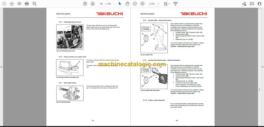
5.7.5 Preheating relay and fuse …………………………………………………………………………………… 194
5.7.6 Plug connection rear wiper motor ………………………………………………………………………… 194
5.7.7 Brake light switch ………………………………………………………………………………………………. 194
5.7.8 Joystick 2000 – electrical functions ……………………………………………………………………… 195
5.7.9 Joystick with thumb wheel – electrical functions ……………………………………………………. 195
5.7.10 Further control elements …………………………………………………………………………………. 195
5.7.11 Electrical power generation …………………………………………………………………………….. 196
5.7.12 Electrical appliances ………………………………………………………………………………………. 196
5.7.13 Repair work: Lighting system ………………………………………………………………………….. 196
5.7.14 Replacing fuses on the printed circuit board ……………………………………………………… 197
5.7.15 Replacing relays on the printed circuit board …………………………………………………….. 197
5.7.16 Replacing relays in the engine compartment …………………………………………………….. 198
5.7.17 Replacing switches in the cab …………………………………………………………………………. 198
5.8 Wheel loaders with ADS: Description of the display and the buttons …………………………… 199
5.8.1 Display …………………………………………………………………………………………………………….. 199
5.8.2 Level 1 …………………………………………………………………………………………………………….. 199
5.8.3 Level 2 …………………………………………………………………………………………………………….. 206
5.9 Work instructions for wheel loaders with ADS and thumb wheel joystick: Joystick settings207
5.10 Replacing hardware components of a wheel loader with ADS ……………………………………. 208
5.10.1 Replacing the ESX…………………………………………………………………………………………. 208
5.10.2 Replacing the display……………………………………………………………………………………… 208
5.10.3 Replacing the display and the ESX ………………………………………………………………….. 209
5.10.4 Speed calibration …………………………………………………………………………………………… 210
5.11 ESX diagnostics function for wheel loaders with ADS ……………………………………………….. 211
5.11.1 Menu Digital Inputs ………………………………………………………………………………………… 211
5.11.2 Menu Analog Inputs ……………………………………………………………………………………….. 211
5.11.3 Menu Digital Outputs ……………………………………………………………………………………… 212
5.11.4 Menu Prop. Outputs……………………………………………………………………………………….. 212
5.12 Replacing the display and the steering column …………………………………………………………. 213
5.12.1 Replacing the printed circuit board …………………………………………………………………… 214
6 Axles and brakes ………………………………………………………………. 215
6.1 General information ………………………………………………………………………………………………. 215
6.1.1 Assembly groups ………………………………………………………………………………………………. 215
6.2 Trouble-shooting …………………………………………………………………………………………………… 216
6.3 Maintenance work: Axles ……………………………………………………………………………………….. 217
6.3.1 Lubricants and fill levels …………………………………………………………………………………….. 217
6.3.2 Checking the oil level in the axles ……………………………………………………………………….. 217
6.3.3 Checking the oil level in the axles ……………………………………………………………………….. 218
6.3.4 Oil change in the axles ………………………………………………………………………………………. 219
6.3.5 Checking the oil level and oil change in the wheel hubs …………………………………………. 220
6.3.6 Checking the brake fluid level ……………………………………………………………………………… 220
6.3.7 Changing brake fluid ………………………………………………………………………………………….. 221
6.3.8 Venting the brake system …………………………………………………………………………………… 221
6.4 Repair work ………………………………………………………………………………………………………….. 222
6.4.1 Dismantling the cardan shaft ………………………………………………………………………………. 222
6.4.2 Replacing the front axle ……………………………………………………………………………………… 223
6.4.3 Replacing the rear axle ………………………………………………………………………………………. 224
6.4.4 Dismantling the flanged reduction gear ………………………………………………………………… 225
6.4.5 Replacing the flanged reduction gear …………………………………………………………………… 227
6.4.6 Replacing the brake disks of the service brake in the rear axle ……………………………….. 228
6.4.7 Dismantling the parking brake and the brake piston unit ………………………………………… 231
9
6.4.8 Checking the brake piston unit ……………………………………………………………………………. 234
6.4.9 Assembling and installing the brake piston unit …………………………………………………….. 235
6.4.10 Reassembling the axle …………………………………………………………………………………… 241
7 Cab …………………………………………………………………………………… 244
7.1 Assembly groups ………………………………………………………………………………………………….. 244
7.2 Trouble-shooting …………………………………………………………………………………………………… 244
7.3 Maintenance work…………………………………………………………………………………………………. 245
7.3.1 Cleaning the wheel loader ………………………………………………………………………………….. 245
7.3.2 Windshield washer system …………………………………………………………………………………. 245
7.3.3 Monthly checks …………………………………………………………………………………………………. 246
7.4 Adjusting instructions …………………………………………………………………………………………….. 246
7.4.1 Adjusting the door lock ………………………………………………………………………………………. 246
7.4.2 Adjusting the locking bolt of the door……………………………………………………………………. 246
7.5 Repair work: Cab ………………………………………………………………………………………………….. 247
7.5.1 Dismantling and installing the steering column paneling …………………………………………. 247
7.5.2 Replacing the doors …………………………………………………………………………………………… 248
7.5.3 Replacing window panes ……………………………………………………………………………………. 249
7.5.4 Replacing the driver`s seat …………………………………………………………………………………. 251
7.5.5 Removing, repairing and installing the driver`s seat ……………………………………………. 251
7.5.6 Replacing a wiper motor …………………………………………………………………………………….. 252
7.5.7 Repair work: Heating / Ventilation ……………………………………………………………………….. 254
7.5.8 Replacing the heating unit ………………………………………………………………………………….. 256
7.5.9 Replacing pedals ………………………………………………………………………………………………. 256
7.5.10 Removing the gas pedal …………………………………………………………………………………. 257
7.5.11 Replacing the inching pedal ……………………………………………………………………………. 257
7.5.12 Openings in the floor of the cab ……………………………………………………………………….. 258
8 Optional equipment …………………………………………………………… 259
8.1 High-Flow auxiliary hydraulics – Electrical circuit diagram ………………………………………….. 259
8.2 Air conditioner ………………………………………………………………………………………………………. 260
8.2.1 Intended purpose and designated use …………………………………………………………………. 261
8.2.2 Overview: Components ……………………………………………………………………………………… 261
8.2.3 Maintenance of the air conditioning unit ……………………………………………………………….. 262
8.2.4 Recommended maintenance intervals ……………………………………………………………….. 264
8.2.5 Failures and trouble shooting ……………………………………………………………………………… 266
8.2.6 Heating capacity ……………………………………………………………………………………………….. 266
8.2.7 Cooling capacity ……………………………………………………………………………………………….. 267
8.2.8 Noise level ……………………………………………………………………………………………………….. 268


