$ 0
0
$ 0
0

Terex 1100×650 PremierTrak Hydraulic, 26×44 PremierTrak Hydraulic Plant User Manual

Format: PDF (Printable Document)

File Language: English

File Pages: 338

File Size: 10.04 MB (Speed Download Link)

Brand: Terex

Model: 1100×650 PremierTrak Hydraulic, 26×44 PremierTrak Hydraulic Plant

Type of Document: User Manual

Categories: ,

$ 50

Share:

Terex 1100×650 PremierTrak Hydraulic, 26×44 PremierTrak Hydraulic Plant User Manual

Terex 1100×650 PremierTrak Hydraulic, 26×44 PremierTrak Hydraulic Plant User Manual

The Terex 1100×650 PremierTrak and 26×44 PremierTrak Hydraulic Crushing Plants are built for high-capacity primary crushing where material flow, jaw pressure, and hydraulic responsiveness must stay consistent. This User Manual teaches operators how the plant should be fed, how the hydraulic adjustment behaves under load, and how the machine reacts when encountering oversized material or uneven feed distribution. It explains belt tracking patterns, chamber pressure changes, jaw clearance settings, and safe startup/shutdown procedures.

Applications & Use Cases

  • Running the crusher at optimal feed rate for consistent output

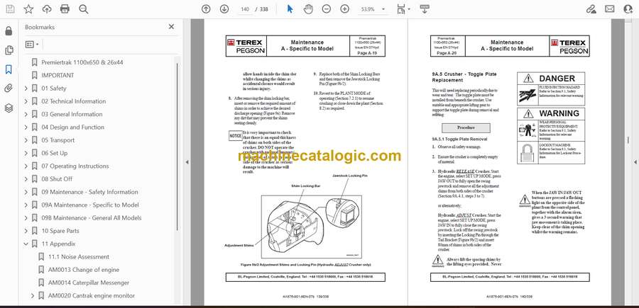
  • Adjusting jaw settings through the hydraulic control system

  • Identifying early signs of jaw wear or uneven crushing pressure

  • Monitoring conveyor behavior to avoid blockages

  • Performing safe shutdowns before chamber inspection

FAQ
Does this manual show how to adjust the hydraulic jaw setting?
Yes. Step-by-step instructions are included.

Is it useful for new crushing plant operators?
Absolutely. It explains real machine behavior, not just specs.

Safety Note
Never enter or reach into the crushing chamber without full lockout and power isolation.

📘 Show Index

Terex 1100×650 PremierTrak Hydraulic, 26×44 PremierTrak Hydraulic Plant Index:

  • Premiertrak 1100×650 & 26×44
  • IMPORTANT
  • 01 Safety
    • 1.1 Warnings and Symbols
    • 1.2 Organisation Measures
    • 1.3 Selection and Qualification of Personnel – Basic Responsibilties
    • 1.4 Safety Instructions Governing Specific Operational Phases
    • 1.4.1 Standard Operation
    • 1.4.2 Special Work In Conjunction with Utilisation of the Plant and Maintenance and Repairs During Operation; Disposal of Parts
    • 1.5 Warning of Special Dangers
    • 1.5.1 Electric Energy
    • 1.5.2 Gas, Dust, Steam, Smoke and Noise
    • 1.5.3 Hydraulic and Pneumatic Equipment
    • 1.5.4.Hazardous Substances
    • 1.6 Transporting, Manoevering and Recommissioning
    • 1.7 Position of Emergency Stop Buttons
    • 1.8 Plant Warning Signs
    • 1.8.1 Location of Warning Signs.
    • 1.8.2 Safety Sign Illustrations
  • 02 Technical Information
    • 2.1 Dimensions
    • 2.2 Plant Description
    • 2.3 Feeder
    • 2.4 Crusher
    • 2.5 Product Conveyor
    • 2.6 Tracks
    • 2.7 Standard Powerpack
    • 2.8 Dustsprays
    • 2.9 Dirt Conveyor *
    • 2.10 Magnetic Separator *
    • 2.11 Manual Folding Hopper *
    • 2.12 Feed Hopper Liner Plates *
    • 2.13 Belt Weigher *
    • 2.14 Water Pump *
    • 2.15 Anti-vandal Guards *
    • 2.16 Manual Clutch *
    • 2.17 Fuel Transfer Pump *
  • 03 General Information
    • 3.1 Introduction
    • 3.2 General information
    • 3.3 Designated Use
    • 3.3.1 Operating Temperature Range
    • 3.4 Crusher Capacity
  • 04 Design and Function
    • 4.1 General Information
    • 4.2 Construction Units
    • 4.2.1 Single Toggle Jaw Crusher
    • 4.2.2 Vibrating Grizzly Feeder
    • 4.2.3 Track Frame
    • 4.2.4 On-Plant Product Conveyor
    • 4.2.5 Magnet
    • 4.2.6 Plant Chutework
    • 4.2.7 Maintenance Platforms
    • 4.2.8 Standard Power-Pack
    • 4.2.9. Dirt Conveyor
    • 4.2.10 Controls
    • 4.2.11 Chassis
    • 4.2.12 Guards
    • 4.2.13 Painting
    • (Başlıksız)
    • 4.2.15 Optional Exclusions *
    • 4.2.16 Specifications
  • 05 Transport
    • 5.1 Safety Information
    • 5.2 Transportation
    • 5.2.1 Manoeuvring
    • 5.2.2 Manoeuvring with the remote RADIO control hand set (where fitted)
    • 5.2.3 Radio Hand Set (where fitted)
    • 5.2.4 Manoeuvring with the remote UMBILICAL control hand set (where fitted)
    • 5.2.5 Unloading
    • 5.2.6 Loading
    • 5.3 Folding Hopper Plates
    • 5.3.1 Hydraulic Folding Hopper – lowering for transport
    • 5.3.2 Manual Folding Hopper * – lowering for transport
  • 06 Set Up
    • 6.1 Safety Information
    • 6.2 Setting Up
    • 6.2.1 Manoeuvring
    • 6.2.2 Unloading
    • 6.2.3 Plant Location Considerations
    • 6.2.4 Setting Up
    • 6.2.5 Hydraulic Folding Hopper
    • 6.2.6 Manual Folding Hopper *
  • 07 Operating Instructions
    • 7.1 Safety Information
    • 7.1.1 Blocked Crusher Situation
    • 7.1.2 Stalled Crusher Procedure (1) APPLICABLE TO HYDRAULIC RELEASE CRUSHER ONLY
    • 7.1.3 Stalled Crusher Procedure (2) FOR HYDRAULIC RELEASE AND HYDRAULIC ADJUST CRUSHERS
    • 7.2 Safe Start-Up Procedure
    • 7.2.1 Plant Start-Up
    • 7.2.2 Active Plant Alarms
    • 7.2.3 Caterpillar C9 Engine Diagnostic Panel
    • 7.2.4 Crusher Hydraulic Systems
    • HYDRAULIC RELEASE MODEL
    • HYDRAULIC ADJUST ONLY MODEL
    • 7.2.5 Crusher Overload Situation (Hydraulic Release Model only)
    • 7.2.6 Crusher Dump Operation (Hydraulic Release Model only)
    • 7.2.7 Safe Operation of the Plant
    • 7.2.8 Checks Prior to Initial Daily Start
    • 7.2.9 Initial Start Up and Running In
    • 7.3 Feeder Remote Stop/Start
    • 7.3.1 Radio Remote Operation (where fitted)
  • 08 Shut Off
    • 8.1 Safety Information
    • 8.2 Closing Down the Plant
    • 8.3 Emergency Stopping of the Engine
    • 8.3.1 Emergency Stop Buttons
    • 8.3.2 Testing Buttons
  • 09 Maintenance – Safety Information
    • 9.0 Safety Information
    • Maintenance Hazards and Procedures
    • Diesel Engine Welding Precautions
    • General Maintenance Safety Precautions
    • 9A.0 Maintenance Description
    • 9A.1 Weights of Components
    • 9A.2 General Information
    • 9A.3 Premiertrak Lubrication and Servicing
    • 9A.3.1 Lubrication Points
    • 9A.3.2 Regular Servicing
    • 9A.3.3 Lubrication and Servicing Schedule
    • 9B.0 Maintenance Description
    • 9B.1 Plant Hydraulic System
    • 9B.1.1 Changing the Suction Filter
    • 9B.1.2 Changing the Return Filter
    • 9B.1.3 Changing the Tank Breather
    • 9B.1.4 Changing then Hydraulic Pressure Filters
  • 09A Maintenance – Specific to Model
    • 9A.0 Maintenance Description
    • 9A.1 Weights of Components
    • 9A.2 General Information
    • 9A.3 Premiertrak Lubrication and Servicing
    • 9A.3.1 Lubrication Points
    • 9A.3.2 Regular Servicing
    • 9A.3.3 Lubrication and Servicing Schedule
    • 9A.3.4 Crusher Lubrication in High Ambient Temperatures
    • 9A.3.5 Importance of Correct Grease
    • 9A.3.6 Lubricant and Oil Types
    • 9A.3.7 Lubrication & Oil Specifications
    • Alternative Models of Crusher
    • HYDRAULIC RELEASE MODEL
    • HYDRAULIC ADJUST ONLY MODEL
    • 9A.4 Crusher – Adjustment of Discharge Opening
    • 9A.4.1 Adjustment – Hydraulic Release Crusher only
    • 9A.4.2 Adjustment – Hydraulic Adjust Crusher only
    • 9A.5 Crusher – Toggle Plate Replacement
    • 9A.5.1 Toggle Plate Removal
    • 9A.5.2 Fitting New Toggle Plate
    • 9A.6 Crusher – Fitting New Toggle Seat
    • 9A.7 Crusher – Manganese Replacement
    • 9A.7.1 Changing the Swing Jaw
    • 9A.7.2 Changing the Fixed Jaw
    • 9A.8 Crusher – Changing of Cheek Plates
    • 9A.8.1 Removal
    • 9A.8.2 Fitment
    • 9A.9 Crusher – Fitting and Removing Flywheel Locking Mechanism
    • 9A.9.1 Loosening the Ringfeder
    • 9A.9.2 Tightening the Ringfeder
    • 9A.10 Feeder – Operation
    • 9A.10.1 Feeder Maintenance
    • 9A.11 Premiertrak Hydraulic System
    • 9A.11.1 General Description
    • 9A.11.2 Track Drives
    • 9A.11.3 Feeder Drive
    • 9A.11.4 Circuit Protection
  • 09B Maintenance – General All Models
    • 9B.0 Maintenance Description
    • 9B.1 Plant Hydraulic System
    • 9B.1.1 Changing the Suction Filter
    • 9B.1.2 Changing the Return Filter
    • 9B.1.3 Changing the Tank Breather
    • 9B.1.4 Changing then Hydraulic Pressure Filters
    • 9B.2 Plant – Electrical System
    • 9B.3 Plant – V Belt Drives
    • 9B.3.1 V Belt Drives – General
    • 9B.3.2 V Belt Drives – Alignment
    • 9B.3.3 V Belt Drives – Adjustment
    • 9B.3.4 V Belt Drives – Replacement
    • 9B.3.5 Method of Drive Belt Tensioning
    • 9B.3.6 Trouble Shooting – Drive Belts
    • 9B.4 Plant – Conveyors
    • 9B.4.1 Training of Belts
    • 9B.4.2 Conveyor Belt Tensioning
    • 9B.4.3 Maintenance of Conveyor(s)
    • 9B.4.4 Cleaning the Conveyor Belts
    • 9B.5 Plant – Overband Magnet (where fitted)
    • 9B.6 Plant – Dust Suppression
    • 9B.7 Plant – Diesel Engine
    • 9B.7.1 Engine – General Information
    • 9B.7.2 Engine – ELC Coolant
    • 9B.7.3 Engine – Check Fuel Level
    • 9B.7.4 Engine – Top Up Fuel Level
    • 9B.8 Engine Power Transmission
    • 9B.8.1 Transmission Types – fitted to models
    • 9B.8.2 Hydraulic Clutch – Grease Lubricated Bearing
    • 9B.8.3 Hydraulic Clutch – Oil Lubricated Bearing
    • 9B.8.3.1 Hydraulic Clutch Trouble Shooting
    • 9B.8.4 Manual Clutch
    • 9B.8.4.1 Manual Clutch – Adjustment
    • 9B.8.4.2 Manual Clutch – Max/Min Adjustment Values
    • 9B.8.5 Fluid Coupling
    • 9B.8.5.1 Fluid Coupling Description
    • 9B.8.5.2 Fluid Coupling – Features
    • 9B.8.5.3 Fluid Coupling – Maintenance
    • 9B.8.5.4 Fluid Coupling – Trouble Shooting
    • 9B.8 Plant – Vehicle Tracks
    • 9B.8.1 Measuring Track Tension
    • 9B.8.2 Adjusting Track Tension
    • 9B.8.3 Track Maintenance
    • 9B.8.4 Drive Oil Filling and Draining
  • 10 Spare Parts
    • 10.1 Jaw Crusher Parts
    • Jaw Crusher Unit – Premiertrak 1100 x 650
    • Jaw Crusher – Assembly Sheet 1
    • Jaw Crusher- Assembly Sheet 2
    • Jaw Crusher – Assembly Sheet 3
    • Jaw Crusher – Assembly Sheet 4
    • Jaw Crusher – Assembly Sheet 5
    • Jaw Crusher – Parts for Hydraulic ADJUST Machine
    • Jaw Crusher – Jawstock Assembly
    • Jaw Crusher – Eccentric Shaft Assembly
    • Jaw Crusher – Tension Rod Assembly
    • Jaw Crusher – Hydraulic Components – Hydraulic RELEASE Crusher only
    • Jaw Crusher – Hydraulic Components – Hydraulic ADJUST Crusher only
    • 10.2 Feeder Parts
    • 4200 x 1060 Grizzly Feeder – Mainframe Assembly
    • 4200 x 1060 One Piece Grizzly Section 50mm Spacing Assembly
    • 4200 x 1060 Grizzly Feeder – Vibrating Unit Assembly
    • 4200 x 1060 Grizzly Feeder – Vibrating Unit Shaft Assembly
    • 10.3 Conveyor Parts
    • Product Conveyor – Conveyor Frame Parts Assembly
    • Product Conveyor – Conveyor Mechanical Parts Assembly
    • Dirt Conveyor – Conveyor Frame Parts Assembly
    • Dirt Conveyor – Conveyor Mechanical Parts Assembly
    • 10.4 Overband Magnetic Separator
    • 10.5 Plant Component Parts
    • Plant Guards Assembly
    • Plant Rubber Seals Assembly
    • Plant Platforms Assembly
    • Plant Feed Hopper Assembly
    • 10.6 Track Parts
    • ‘S’ Mark Tracks
    • ‘T’ Mark Tracks
    • 10.7 Hydraulic Parts
    • Hydraulic System Components
    • Hydraulic Parts – HFO Clutch
    • Hydraulic Oil Reservoir
    • 10.8 Electrical Parts
    • 10.9 Warning Labels
    • 10.10 Hydraulic Engine Clutch
  • 11 Appendix
    • 11.1 Noise Assessment
    • AM0013 Change of engine
    • AM0014 Caterpillar Messenger
    • AM0020 Cantrak engine monitor
      • Introduction
      • Buttons
      • Button Icons
      • Button Lock
      • Displays
      • Data Parameters and Icons
      • Alarm Messages
      • Configuration Options
    • Product Advisory Bulletin PAB 010 04
    • Hydraulic Deflector Plate
    • Fuel Transfer Pump
    • Water Pump
    • Milltronics MCS Belt Weigher
    • Alternative Remote Feeder Control
  • 12 Notes

Terex

Latest Product

0
    0
    Your Cart
    Your cart is emptyReturn to Shop