$ 0
0
$ 0
0

Terex SKSS-13 Infinity Blasthole Drill Service Manual (91-A11-374)

Format: PDF (Printable Document)

File Language: English

File Pages: 778

File Size: 171.98 MB (Speed Download Link)

Brand: Terex

Model: SKSS-13 Infinity Blasthole Drill

Book No: 91-A11-374

Type of Document: Service Manual

Categories: ,

$ 50

Share:

Terex SKSS-13 Infinity Blasthole Drill Service Manual (91-A11-374)

Terex SKSS-13 Infinity Blasthole Drill Service Manual (91-A11-374)

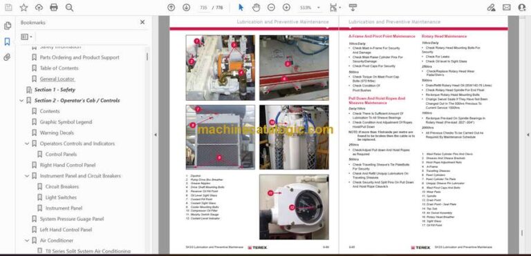
The Terex SKSS-13 Infinity Blasthole Drill is engineered for deep, precise drilling in demanding mining environments. This Service Manual dives into rotary head mechanics, air system routing, hydraulic feed cylinder behavior, and structural stress points that often show early wear. Its diagrams help technicians visualize how each subsystem interacts under load, especially during continuous drilling cycles.

Applications & Use Cases

  • Diagnosing rotary head vibration or torque loss

  • Servicing feed cylinders, air compressors, and drive motors

  • Tracking hydraulic pressure irregularities

  • Preparing the drill for sustained high-depth drilling operations

  • Identifying worn bushings, bearings, and seals

FAQ
Does the manual include air and hydraulic schematics?
Yes, complete layouts with flow direction markers.

Is it helpful for heavy mining operations?
Definitely. It covers common fault patterns seen in long drilling shifts.

Safety Note
Lock out the air system before opening any compressor or feed components.

📘 Show Index

Terex SKSS-13 Infinity Blasthole Drill Index:

  • Introduction
    • Safety Information
    • Parts Ordering and Product Support
    • Table of Contents
    • General Locator
  • Section 1 – Safety
  • Section 2 – Operator’s Cab / Controls
    • Contents
    • Graphic Symbol Legend
    • Warning Decals
    • Operators Controls and Indicators
      • Control Panels
    • Right Hand Control Panel
    • Instrument Panel and Circuit Breakers
      • Circuit Breakers
      • Light Switches
      • Instrument Panel
    • System Pressure Guage Panel
    • Left Hand Control Panel
    • Air Conditioner
      • T8 Series Split System Air Conditioning Manual
  • Section 3 – Main Frame / Crawlers
    • Contents
    • Main Frame Repair – General
      • Main Frame Repair
    • Leveling Jacks
      • Leveling Jacks
      • Leveling Jack Cylinders
    • Mast Elevating Cylinders
      • Mast Elevating Cylinders
      • Remove
      • Repair
      • Replace
    • Crawler Assembly
      • Crawler Component Repair
    • Metric Bolt Torque Specifications
    • Track Maintenance
      • Before Operating the Machine
      • General Maintenance
    • Track Tension Adjustment
      • Hydraulic Tensioner
      • Description
      • Nitrogen Tensioner
    • Hydraulic Tensioner
      • Repair
    • Nitrogen Tensioner Assembly
    • Nitrogen Tensioner – Fitting Instructions
      • Nitrogen Tensioner – Pressure Check
      • Nitrogen Tensioner – Pressure Release
    • Track Chain – Separate
    • Track Chain – Repair
      • Track Link – Repair & Replace
      • Track Link – Description
    • Track Shoes Installation
      • Track Link Position
      • Track Shoe – Mounting to Tracsk Chain
    • Track Shoe Bolt Torque (Direct Torque Method)
    • Track Shoe Bolt Torque (Torque Turn Method)
    • Track Chain and Shoe Installation
      • Track Chain with Shoes
      • Track Chain & Shoe – Assembly & Installation
    • Final Drive
      • Final Drive – General Description
    • Final Drive Unit Removal
      • Removal from Track Frame
    • Final Drive Unit Installation
      • Installation into Track Frame
    • Final Drive Maintenance
      • Oil Check / Change
    • Final Drive Oil
      • Specifications
      • Recommended Oil
    • Final Drive Assembly
      • Parking Brake – Description
    • Final Drive – Disconnect & Parking Brake
      • Towing Procedure – Gear Drive Disconnect
      • Parking Brake – Removal & Installation
    • Idler Unit Assembly
      • Idler Unit – Assembly
    • Idler Unit Removal
      • Idler Unit – Removal
    • Track and Support Rollers
      • General Description
      • Track Roller – Removal & Disassembly
      • Track and Support Roller – Assembly
      • Track and Support Roller – Test and Install
    • Auxiliary Crane
      • Hydraulic Crane (Auxiliary Crane)
      • Load Lift Capacities
      • Maintenance
  • Section 4 – Engine / Drive Train / Compressor
    • Contents
    • Power Group Locator
    • Cummins Engine
      • Engine Fuel System
      • Construction
      • Combo Fuel Filter Head & Pump Manifold
      • FS1006 Fuel Filter with Water Separator
      • Fuel Manifold with Integrated FSO Valve
      • Fuel Connections
      • Pre Filters
      • Wiring with EFS Power Relay
      • Pressure and Temperature Sensors
      • Operation
      • QST30 Electric Fuel Supply System
      • Oil Reserve Systems
      • Engine Oil Reserve System (Basic Circuit)
      • LED Monitor Readings
      • Adjustment of Running Oil Level
      • Oil Reserve Basic Circuit
      • Oil Pressure Switch
      • Oil Reserve System
      • Troubleshooting
      • Maintenance
    • Engine and Compressor Air Cleaner
      • Engine and Compressor Air Cleaner Service
    • Compressor Assembly
    • Flexible Drive Coupling
      • Flexible Drive Coupling Service
    • Pump Drive
      • Pump Identification
      • Pump Drive Assembly – Removal and Replacement
    • Pump Drive Gearbox
      • Pump Drive Gearbox Repair
      • 3″ Input Shaft Assembly
    • Hydraulic Pump
      • Hydraulic Pumps – Removal and Replacement
    • Compressor Installation
      • Compressor Drive Coupling
      • Compressor Installation
      • Compressor Drive Coupling – Removal and Replacement
    • Compressor Shaft Seal
      • Compressor Shaft Seal
    • Low Pressure Compressosr
      • Safety
      • Description
      • Compressed Air Functions
    • Compressor Oil Circuit
      • Diagram Legend
      • Compressor Oil Circuit – COLD
      • Compressor Oil Circuit – HOT
      • Compressor Oil Circuit – Shut Down
    • Compressor Air Circuits – 2400cfm @ 100psi
      • Diagram Legend
      • Shutdown
      • Start Up
      • Run Loaded
      • Drilling Air On
    • Compressor Functional Description
    • Compressor Operation
      • Operation
    • Compressor Maintenance
      • General Maintenance
      • Discharge Check Valve
      • Compressor Receiver Tank Assembly
      • Separator Elements
      • Separator Elements – Remove & Replace
      • Scavenge Line
      • Compressor Discharge Temperature Gauge, Switch and Sender
      • Minimum Pressure Valve
      • Minimum Pressure / Check Valve Maintenance
      • Thermal Bypass Valve
      • Thermal Bypass Valve Maintenance
      • Oil Stop Valve
      • Compressor Fluid Filter
      • Changing Filter Elements
      • Bearing Oil Filter
      • Compressor Inlet Valve Control System
      • Compressor Inlet Valve Control System
      • Relieving Regulators
      • System Blowdown Valve
      • Running Blowdown Valve
      • Running Blowdown Maintenance
      • Moisture Separator Maintenance
      • Auxiliary Regulators
      • Auxiliary Regulator Maintenance
      • Troubleshooting
    • Aluminum Tube Air to Oil Cooler
      • Compressor Oil Cooler
    • Radiator Cooler
      • Radiator Hydraulic Oil Cooler Assembly
      • Radiator / Oil Cooler Repair
  • Section 5 – Dust Control System
    • Contents
    • Dust Control System
      • Dust Control Systems
      • Dust Collector
      • Dust Collector Assembly
    • Water Injection
      • Water Tanks
      • Water Tank Top up Soleniod Valve
      • Water Injection Relief Valve
      • Water Injection Control
      • Water Injection Basic Circuit
    • Water Pump
      • Pump Specifications
      • Servicing Instructions
      • Parts List
      • Replacing Piston Cup Seals
      • Replacing Suction and Discharge Valves
      • Replacing Power End Bearings
      • Servicing the Wrist Pin Bearings
      • Fastener Torque Requirements
      • Recommended Lubricants
      • Water Pump Motor Repair
      • Water Injection Hydraulic Control Valve Repair
      • Water Pump Drive Coupling
      • Level and Flow Transducer
  • Section 6 – Mast / Rotary Drive / Pipe Rack
    • Mast Weldment
      • Mast Repair
    • Mast Assembly
      • Mast Assembly
      • Mast Pivot
    • Feed Cylinders
      • Feed Cylinder – Removal
      • Feed Cylinder Assembly
      • Repair
      • Installation
    • Hoist / Pulldown Cable Adjustment
      • Hosit / Pulldown Cable Adjustment
      • Hoist / Pulldown Cable Replacement
    • Rotary Drive Assembly
      • Rotary Head Guide Alignment
      • Rotary Head – Drive System
      • Rotary Drive – Removal from Mast
      • Rotary Drive – Installation
    • Rotary Drive Gearbox
      • Rotary Drive Gearbox – Item Listing
      • Rotary Head Bull Shaft Bearing Nut
      • Rotary Drive Gearbox – Repair
      • Air Swivel
    • Winch Assembly
      • Precautions on the use of Winches
      • Wedge Socket
      • Grooved Drums
      • Plain (Smooth) Drums
      • Drums – Multiple Layers
      • Winch Assembly Service
      • BG8A and BG8B Hydraulic Winch Service Manual
    • Deck Wrench
    • H.O.B.O. Wrench
      • Breakout System – HOBO
      • Hydraulic Operated Bit Basket – HOBB
      • Pipe Safety Arm
    • Pipe Positioner
    • Carousel Pipe Rack
      • Major Components
      • Rod Handling – Carousel Indexing
      • Carousel Pipe Rack Assembly
      • General Information
      • Pipe Rack Bearings – Removal
      • Pipe Rack Componetns – Inspection
      • Pipe Rack – Assembly and Installation
      • Pipe Rack Roller – Remove and Replace
      • Pipe Rack Roller – Disassembly and Assembly
  • Section 7 – Hydraulic Systems
    • Hydraulic Symbols
    • Pressure Setting Sequence
      • Pressure Setting Sequence
    • Hydraulic Tank
      • Hydraulic Tank
      • Return Hydraulic Filters
    • Main Return and Case Drain Filters
      • Routine Maintenance
      • Changing Filter Elements
    • Main Hydraulic Pumps
      • Pump Identification
    • Right Track, Left Track / Rotation Pumps
      • Hydraulic Piston Pumps – Removal and REplacement
      • AA4VG 180 Hydraulic Pump HD/D Control
      • Technical Data
      • Port Locations
      • Setting Procedure
      • Charge Pressure, High Pressure, P.O.R. and Zero Position Settings
      • Set Charge Pressure – 450psi (31 bar)
      • Set Crossover Relief (High Pressure) – 5500psi (380 bar)
      • Set Pressure Override (P.O.R) – 5000psi (345 bar)
      • Set Mechanical Zero Position – HD Pump Control
      • Set Hydraulic Zero Position – HD Pump Control
      • Removal and Inspection of Charge Pump
      • Removal and Installation of Shaft Seal
      • Routine Maintenance
    • Charge Circuit
    • Charge Filter
      • Routine Maintenance
      • Changing Filter Elements
    • Main Pumps Circuit
      • Main Pumps Circuit
    • Loop Filters
      • Routine Maintenance
      • Changing Filter Elements
    • Rotation Circuit
      • Rotation Circuit
    • Rotary Drive Gearbox Motor
      • Rotary Drive Gearbox Motor – Test and Repair
      • Shaft Seal Replacement
      • Trouvle Shooting
    • Tram Circuit
      • Tram Circuit
    • Feed and Auxiliary Pump Circuit
      • Hydraulic Piston Pumps – Removal and Replacement
      • Feed and Auxiliary Functions Pump
      • Repair Instructions
      • Pump Replacement – Start Up
    • Hydraulic Systems
      • Auxiliary and Feed Circuits
    • Main Control Valves
      • Valve Stand Assembly
    • MP18 Valve – Jack and Mast Raise Valve
    • MP22 Valve – Hoist and Pulldown Control
    • 4WE6 – Aux. Functions and Mast Valves
      • Repair Kits
      • Exploded View of 4WE6
    • Counterbalance Valves
      • Counterbalance Valve Adjustment
    • Pilot Control Manifold
    • Control Valve Assembly
      • Auxiliary Pump Load Solenoid Valve
    • Hydraulic Feed Circuit
    • Feed Valve Assembly
    • Jack Control and Mast Elevating Circuit
      • Jack Control and Mast Elevating Circuit
    • Leveling Jack Cylinders
      • Counterbalance Valve Test Procedure
    • Mast Elevating Cylinders
      • Counterbalance Valve Test Procedure
    • Auxiliary Functions Circuit
      • Auxiliary Functions Circuit
    • Hydraulic Operated Breakout Wrench
      • Setting of HOBO Sequence Valves
    • Cooler Fan Circuit
      • Fan Motor Circuit
    • Cooler Fan Motor
      • Hydraulic Motor
    • Hydraulic Thermostatic Valve
      • Hydraulic Cooler – Thermal Valve
    • Central Lube
      • Hydraulic Circuit
    • Air Conditioner Compressor Drive Circuit
    • Air Conditioner Drive Motor
      • Design
      • Operational Check
      • Shaft Seal Replacement
      • Screw Tightening Torque
      • Gear Backlash
      • Specifications
      • Parts List
    • Water Injection Circuit
      • Water Injection Valve
    • Water Injection Valve
      • Introduciton
      • Valve Stack Assembly
      • Segment Alterations
      • Pulsar Solenoid Removal and Plug
      • Recommended Test Stand
      • Final Stack Adjustment
      • Assembly Drawing – VBL Bypass Inlet Segment Parts List
      • Assembly Drawing – VPL Work Segment Parts List
    • Water Pump Motor
      • Water Pump Motor Repair Information
      • Shaft Seal Repair
    • Hydraulic Cylinder Repair
      • General Information
      • H Head
      • N Head
      • Z Head
      • Z Head ( Two Piece)
      • K Head
      • M Head
      • Z Piston
      • Z Piston (Threaded)
      • H & K Piston
      • M Piston
      • N Piston
  • Section 8 – Electrical Components
    • Electrical Locator
      • Electrical Locator Parts List
    • Jump Starting
    • Batteries
    • Welding Precautions
    • Vigilante Guide
      • Important Information
      • PLC
      • EEPROM
      • Output Card
      • Touchscreen
      • Laser Depth System
      • Safety Instructions & Precautions
      • Pipe in Hole Detection
      • Distance Meter
      • Start Up and Shut Down
      • Hydraulic Function Enable
      • Alarms
      • Solenoid Control
      • Auto Lube
      • Hammer Oiler System
      • Gauges
      • Pressure Transducer
      • Level Transducer
      • Hammer Oil Level Transducer
      • Temperature Transducer
      • Water Flow Transducer
      • Inclinometers
      • Head Speed Module
      • Level Switches
      • Dust Suppression
      • Turkey Spray
      • Water Suppression Tank – Top Up
    • Vigilante System Component Information
      • Head Speed Module
      • Inclinometer
      • Ladder Prox Switch
      • LDM 40 A Laser
      • Level Switches – Capacitive Level Switch (Hydraulic Oil Level)
      • Radiator Level Switch
      • Level Transducer – Electronic Level Sensor
      • Hammer Oil Level Transducer
      • Pressure Transducer – Combined Pressure Sensor
      • Temperature Transducer – Control Monitor for Temperature Sensors
  • Section 9 – Lubrication and Preventive Maintenance
    • Central Lube System
      • Hydraulic Control Schematic
      • Auto Lube
      • Central Lube Pump Module
      • Central Lube Pump
    • Bit Oiler Tank Assembly
    • Bit Oil Circuit
    • Bit Oil System
      • Air Service Unit Components
      • Filter Regulator
      • Air Line Oiler
      • Fire Ball 425 Pump – Instructions
    • Pipe Thread Lubricator
      • Air Service Unit
      • Filter Regulator
      • Air Line Lubricator
      • Pipe Thread Pump
    • Filter Locator
    • Lubrication General
      • Equipment Lubrication
      • Care of Lubrication Points
    • Lubrication and Preventive Maintenance
      • Safety
      • Track Gear
      • Engine Maintenance
      • Air Cleaners
      • Air Filter Elements
      • Alternator Maintenance
      • Pump Drive and Drive Shaft Maintenance
      • Compressor Maintenance
      • Cooler Packs
      • A-Frame and Pivot Point Maintenance
      • Pull Down and Hoist Ropes and Sheaves Maintenance
      • Hydraulic System Maintenance
      • Hydraulic Maintenance
      • Water Pump Maintenance
      • Cab Maintenance
      • Air Conditioner Maintenance
      • Battery Maintenance
      • Lubrication System Maintenance
      • Fire Suppression Maintenance
    • Lubrication and Maintenance Chart 250hr
    • Lubrication and Maintenance Chart 500hr
    • Lubrication and Maintenance Chart 1000hr
    • Lubricant Specifications
      • Hydraulic System
      • Hydraulic Tank Capacity
      • Compressor Lubrication
      • Compressor Lubricant Specifications
      • Lubricating Grease
      • Gear Lubricant
      • Scheduled Oil Sampling Analysis
    • Torque Valves for Split Flange Connections

Terex

Latest Product

0
    0
    Your Cart
    Your cart is emptyReturn to Shop