Format: PDF (Printable Document)
File Language: English
File Pages: 853
File Size: 34.12 MB (Speed Download Link)
Brand: Terex
Model: SKSS-15 Series Infinity Blasthole Drill
Book No: 1H67C05, 1H67C43
Type of Document: Service Manual
$ 50
This Service Manual for the Terex SKSS-15 Infinity Drill provides an in-depth look at the machine’s rotary system, hydraulic feed circuits, structural mast design, and air delivery components. It’s an essential resource for technicians dealing with drilling efficiency issues, overheating rotary heads, or irregular torque profiles in demanding mining environments.
Applications & Use Cases
Rebuilding the rotary drive assembly
Tracking down air pressure inconsistencies
Inspecting mast alignment under load
Diagnosing feed motor pulse or slowdown
Maintaining lubrication paths for high-cycle drilling
FAQ
Does the manual cover deep drilling-specific maintenance?
Yes, it explains wear patterns unique to high-depth operations.
Are rotary torque specs included?
Yes, with precise tolerances and wear limits.
Safety Note
Secure the mast structure fully before conducting overhead component service.
Introduction
Parts Ordering & Product Support ………………………………………………………………………….. i
Safety Information …………………………………………………………………………………………………. ii
Product Description ……………………………………………………………………………………………… iii
Manual Contents…………………………………………………………………………………………………… iii
Table of Contents………………………………………………………………………………………………….. iv
General Locators ………………………………………………………………………………………………… xvi
Section 1
Safety…………………………………………………………………………………….1-1
Personal Protective Equipment…………………………………………………………………………………….. 1-2
Noise ………………………………………………………………………………………………………………………… 1-2
Electrical Contact: ………………………………………………………………………………………………………. 1-2
Overhead and Buried Utilities ……………………………………………………………………………………….. 1-2
Contact With Electric Wires…………………………………………………………………………………………. 1-3
Contaminated Air ………………………………………………………………………………………………………… 1-3
Machine Stability…………………………………………………………………………………………………………. 1-4
Moving and Rotating Parts …………………………………………………………………………………………… 1-5
High Pressure Air or Fluid ……………………………………………………………………………………………. 1-5
BeforeOperation…………………………………………………………………………………………………………….1-5
During Operation………………………………………………………………………………………………………… 1-6
Maintenance ………………………………………………………………………………………………………………. 1-8
Safety Locators…………………………………………………………………………………………………… 1-9
Section 2
Operator’s Cab/ Controls ……………………………………………………… 2-1
Operator’s Controls and Indicators ……………………………………………………………………… 2-2
Control Panels …………………………………………………………………………………………………………… 2-2
Right Hand Control Panel ……………………………………………………………………………………. 2-3
Instrument Panel and Circuit Breakers ………………………………………………………………… 2-4
Circuit Breakers …………………………………………………………………………………………………………. 2-4
Light Switches……………………………………………………………………………………………………………. 2-5
Instrument Panel ………………………………………………………………………………………………………… 2-5
System Pressure Guage Panel …………………………………………………………………………….. 2-6
Left Hand Control Panel ………………………………………………………………………………………. 2-8
Foot Control Pedals ………………………………………………………………………………………….. 2-14
Thread Grease Switch ………………………………………………………………………………………….. 14
Pipe Safety Arm Override Switch ………………………………………………………………………….. 14
Foot Control Pedals …………………………………………………………………………………………….. 14
Air Conditioner …………………………………………………………………………………………………….. 15
Contents ………………………………………………………………………………………………………………… 2-17
Introduction………………………………………………………………………………………………………………. 2-19
Unit Specification………………………………………………………………………………………………………. 2-20
Technical Data and Control Settings ……………………………………………………………………………. 2-23
Installation and Commissioning ………………………………………………………………………………….. 2-25
PDF created with pdfFactory trial version www.pdffactory.com
SKSS Introduction v
Table of Contents
Operating Instructions ……………………………………………………………………………………………….. 2-32
Routine Maintenance Proceedures ……………………………………………………………………………… 2-34
Fault Diagnosis ………………………………………………………………………………………………………… 2-38
Warranty………………………………………………………………………………………………………………….. 2-48
Basic Spare Parts Listing…………………………………………………………………………………………… 2-49
Reference Drawings …………………………………………………………………………………………………. 2-51
Section 3
Main Frame – Crawlers ………………………………………………………….. 3-1
Main Frame Repair …………………………………………………………………………………………….. .3-2
Leveling Jacks ……………………………………………………………………………………………………. 3-3
Leveling Jack Cylinders …………………………………………………………………………………………… 3-4
Remove ……………………………………………………………………………………………………………………. 3-4
Repair ………………………………………………………………………………………………………………………. 3-4
Replace…………………………………………………………………………………………………………………….. 3-4
Mast Elevating Cylinders …………………………………………………………………………………….. 3-5
Remove ……………………………………………………………………………………………………………………. 3-7
Repair ………………………………………………………………………………………………………………………. 3-7
Replace…………………………………………………………………………………………………………………….. 3-7
Crawler Assembly ……………………………………………………………………………………………….. 3-8
Crawler Component Repair …………………………………………………………………………………………. 3-9
Metric Bolt Torque Specifications ………………………………………………………………………. 3-10
Track Maintenance…………………………………………………………………………………………….. 3-11
Before Operating Machine: …………………………………………………………………………………………. 3-11
GeneralMaintenance …………………………………………………………………………………………………. 3-11
Track Tension Adjustment …………………………………………………………………………………. 3-12
Hydraulic Tensioner …………………………………………………………………………………………………… 3-13
Correct Track Tension ……………………………………………………………………………………………….. 3-13
Description………………………………………………………………………………………………………………. 3-14
Nitrogen Tensioner ……………………………………………………………………………………………………. 3-15
Hydraulic Tensioner ………………………………………………………………………………………….. 3-16
Repair …………………………………………………………………………………………………………………….. 3-16
Nitrogen Tensioner Assembly ……………………………………………………………………………. 3-17
Track Tension Adjustment …………………………………………………………………………………. 3-18
Nitrogen Tensioner – Filling Instructions………………………………………………………………………… 3-18
Nitrogen Tensioner – Pressure Check ………………………………………………………………………….. 3-20
Nitrogen Tensioner – Pressure Release ……………………………………………………………………….. 3-20
Track Chain – Separate ………………………………………………………………………………………. 3-22
Track Chain Repair ……………………………………………………………………………………………. 3-24
Track Link – Repair & Replace ……………………………………………………………………………………. 3-24
Track Link – Description …………………………………………………………………………………………….. 3-25
Track Shoes Installation…………………………………………………………………………………….. 3-26
Track Link Position ……………………………………………………………………………………………………. 3-26
Track Shoe – Mounting to Track Chain …………………………………………………………………………. 3-26
Track Shoe – Mounting to Track Chain …………………………………………………………………………. 3-27
Torque Turn Method…………………………………………………………………………………………………… 3-27
Track Shoe – Retightening………………………………………………………………………………………….. 3-27
Track Shoe Bolt Torque (Direct Torque Method) …………………………………………………. 3-28
Track Shoe Bolt Torque (Torque Turn Method) …………………………………………………… 3-29
Track Chain and Shoe Installation ……………………………………………………………………… 3-30
Track Chain with Shoes …………………………………………………………………………………………….. 3-30
Track Chain & Shoe – Assembly & Installation ………………………………………………………………. 3-30
Final Drive…………………………………………………………………………………………………………. 3-32
Final Drive – General Description ………………………………………………………………………………… 3-32
Final Drive Unit Removal……………………………………………………………………………………. 3-33
Removal from Track Frame ……………………………………………………………………………………….. 3-33
Installation into Track Frame ………………………………………………………………………………………. 3-34
Final Drive Maintenance…………………………………………………………………………………….. 3-35
Oil Check / Change…………………………………………………………………………………………………… 3-35
Final Drive Oil ……………………………………………………………………………………………………. 3-36
Specifications …………………………………………………………………………………………………………… 3-36
Recommended Oil ……………………………………………………………………………………………………. 3-36
Final Drive Assembly …………………………………………………………………………………………. 3-37
Parking Brake – Description ……………………………………………………………………………………….. 3-38
Final Drive Disconnect ………………………………………………………………………………………. 3-39
Final Drive – Disconnect & Parking Brake…………………………………………………………… 3-40
Towing Procedure – Gear Drive Disconnect ………………………………………………………………….. 3-40
Parking Brake – Removal & Installation ………………………………………………………………………… 3-40
IdlerAssembly …………………………………………………………………………………………………… 3-41
Idler Unit Removal …………………………………………………………………………………………….. 3-43
Idler Unit – Assembly………………………………………………………………………………………….. 3-45
Track and Support Rollers…………………………………………………………………………………. 3-49
General Description ………………………………………………………………………………………………….. 3-49
Track Roller – Removal & Disassembly ……………………………………………………………………….. 3-51
Support Roller – Removal & Disassembly ……………………………………………………………………. 3-52
Track and Support Roller – Assembly…………………………………………………………………………… 3-53
Track and Support Roller – Test and Install……………………………………………………………………. 3-54
Auxiliary Crane………………………………………………………………………………………………….. 3-56
Palfinger Hydraulic Crane Operators Manual ………………………………………………………….. 3-57
Contents………………………………………………………………………………………………………………….. 3-58
Before Operation of Crane …………………………………………………………………………………………. 3-64
Start Operation of Crane ……………………………………………………………………………………………. 3-65
Section 4
Engine / Drive Train / Compressor ………………………………………… 4-1
Power Group Locator ………………………………………………………………………………………….. 4-2
Engine………………………………………………………………………………………………………………… 4-3
Engine Fuel System……………………………………………………………………………………………………. 4-4
Engine Oil Reserve System Circuit …………………………………………………………………………….. 4-12
Engine Oil Reserve System……………………………………………………………………………………….. 4-12
Oil Reserve Systems ………………………………………………………………………………………………… 4-14
LED Monitor Readings ………………………………………………………………………………………………. 4-15
PDF created with pdfFactory trial version www.pdffactory.com
SKSS Introduction vii
Table of Contents
Signals ……………………………………………………………………………………………………………………. 4-15
Adjustment of Running Oil Level …………………………………………………………………………………. 4-15
Servicing …………………………………………………………………………………………………………………. 4-16
Troubleshooting………………………………………………………………………………………………………… 4-16
Oil Reserves Systems – Maintenance………………………………………………………………………….. 4-17
Engine and Compressor Air Cleaners ………………………………………………………………… 4-18
Engine and Compressor Air Cleaner Service ………………………………………………………….. 4-19
Inspection and General Service ………………………………………………………………………………….. 4-19
Engine and Compressor Air Cleaner Service ……………………………………………………………….. 4-21
Safety Element Service……………………………………………………………………………………………… 4-21
Flexible Drive Coupling Service …………………………………………………………………………. 4-22
Adaptor Flanges ……………………………………………………………………………………………………….. 4-22
Centering Flanges…………………………………………………………………………………………………….. 4-22
Rubber Element ……………………………………………………………………………………………………….. 4-22
Tube Assembly…………………………………………………………………………………………………………. 4-22
Mounting Screws andAdhesive ………………………………………………………………………………….. 4-23
Pump Drive Assembly – Removal and Replacement ……………………………………………………… 4-25
Pump Drive……………………………………………………………………………………………………….. 4-25
Pump Identification ……………………………………………………………………………………………………. 4-26
Pump Drive Gearbox …………………………………………………………………………………………. 4-27
Pump Drive Gearbox – Repair …………………………………………………………………………………….. 4-28
3″ Input Shaft Assembly …………………………………………………………………………………………….. 4-30
Hydraulic Piston Pumps ……………………………………………………………………………………. 4-31
Hydraulic Piston Pumps – Removal and Replacement …………………………………………………… 4-31
Hydraulic Piston Pumps – Repair ………………………………………………………………………………. 4-31
Tram and Rotation Pumps …………………………………………………………………………………. 4-32
Hydraulic Piston Pumps ……………………………………………………………………………………. 4-69
Hydraulic Piston Pumps – Removal and Replacement …………………………………………………… 4-69
Hydraulic Piston Pumps – Repair ………………………………………………………………………………. 4-69
Feed and Auxiliary Pump …………………………………………………………………………………… 4-70
Hydraulic Gear Pumps …………………………………………………………………………………….. 4-101
Hydraulic Gear Pumps – Removal and Replacement …………………………………………………….4-101
Hydraulic Gear Pumps – Repair ………………………………………………………………………………..4-101
Compressor Installation…………………………………………………………………………………… 4-115
Compressor Replacement and Drive Coupling Maintenance………………………………….. 4-116
Disassembly …………………………………………………………………………………………………………… 4-116
Before Installation of New or Rebuilt Compressor: ……………………………………………………….. 4-117
Reassembly ……………………………………………………………………………………………………………. 4-118
Before Start-Up of New or Rebuilt Compressor: …………………………………………………………… 4-118
Drill Compressor ……………………………………………………………………………………………… 4-119
High Pressure Compressor……………………………………………………………………………… 4-120
Section 1 Safety ……………………………………………………………………………………………………..4-120
General …………………………………………………………………………………………………………………..4-120
Pressure Release …………………………………………………………………………………………………….4-120
Fire and Explosion…………………………………………………………………………………………………….4-121
Moving Parts ……………………………………………………………………………………………………………4-121
Toxic and Irritating Substances …………………………………………………………………………………..4-121
Electrical Shock ……………………………………………………………………………………………………….4-122
Lifting………………………………………………………………………………………………………………………4-122
Section 2 Description……………………………………………………………………………………………..4-123
Introduction………………………………………………………………………………………………………………4-123
Compressed Air Functions ………………………………………………………………………………………..4-123
Sullair Compressor Unit …………………………………………………………………………………………….4-124
Compressor Discharge System…………………………………………………………………………………4-125
Compressor Cooling and Lubrication System………………………………………………………………4-126
Compressor Fluid Circuit …………………………………………………………………………………. 4-127
Compressor Condensation Table…………………………………………………………………….. 4-130
Compressor Air Circuit 1475cfm @ 500psi ……………………………………………………….. 4-131
Compressor Description………………………………………………………………………………….. 4-143
Air Inlet System………………………………………………………………………………………………………..4-143
Instrument Group ……………………………………………………………………………………………………..4-145
Protection System…………………………………………………………………………………………………….4-145
Compressor Operation ……………………………………………………………………………………. 4-146
Section 3 Operation ……………………………………………………………………………………………….4-146
General …………………………………………………………………………………………………………………..4-146
Purpose Of Controls …………………………………………………………………………………………………4-146
Initial Start-up Procedure ……………………………………………………………………………………………4-148
Subsequent Start-up Procedure………………………………………………………………………………….4-149
Shutdown Procedure ………………………………………………………………………………………………..4-149
General Operating Instructions …………………………………………………………………………………..4-149
Compressor Maintenance ……………………………………………………………………………….. 4-150
Section 4 General Maintenance ……………………………………………………………………………..4-150
General …………………………………………………………………………………………………………………..4-150
Daily Operation ………………………………………………………………………………………………………..4-150
Maintenance After Initial 50 Hours Of Operation…………………………………………………………….4-151
Maintenance Every 250 Hours ……………………………………………………………………………………4-151
Maintenance Every 500 Hours ……………………………………………………………………………………4-151
Maintenance Every 1000 Hours ………………………………………………………………………………….4-151
Main Drive Shaft Seal Replacement ……………………………………………………………………………4-152
Interstage Tube ………………………………………………………………………………………………………..4-155
Discharge Check Valve ……………………………………………………………………………………………..4-156
Separator/Receiver Tank……………………………………………………………………………………………4-157
Minimum Pressure / Check Valve ……………………………………………………………………………….4-159
Scavenge Line …………………………………………………………………………………………………………4-160
Scavenge Line Sight Glass ………………………………………………………………………………………..4-160
Scavenge Line Oriface………………………………………………………………………………………………4-160
Compressor Discharge Temperature Switches, Senders and Gauges…………………………….4-161
Thermal/Bypass Valve ………………………………………………………………………………………………4-162
Fluid Stop Valve ………………………………………………………………………………………………………..4-164
Compressor Fluid Filter …………………………………………………………………………………………….4-166
Inlet Valve ………………………………………………………………………………………………………………..4-168
Compressor Regulation………………………………………………………………………………………….4-170
Relieving Regulators …………………………………………………………………………………………………4-170
Reducing Regulators ………………………………………………………………………………………………..4-173
System Blowdown Valve ……………………………………………………………………………………………4-175
Running Blowdown Valve …………………………………………………………………………………………..4-176
PDF created with pdfFactory trial version www.pdffactory.com
SKSS Introduction ix
Table of Contents
Moisture Separator Maintenance…………………………………………………………………………………4-178
Auxiliary Regulator…………………………………………………………………………………………………….4-179
Troubleshooting………………………………………………………………………………………………………..4-181
Compressor Oil Cooler Assembly…………………………………………………………………….. 4-185
Compressor oil cooler ……………………………………………………………………………………………….4-185
Radiator/Hydraulic Oil Cooler Assembly …………………………………………………………… 4-186
Radiator/Oil Cooler Repair ……………………………………………………………………………….. 4-187
High Pressure Compressor Fluid Cooler ………………………………………………………….. 4-189
Radiator Cooler ……………………………………………………………………………………………….. 4-197
Section 5
Dust Control Systems…………………………………………………………… 5-1
Water Injection…………………………………………………………………………………………………….. 5-3
Water Injection Control ………………………………………………………………………………………………… 5-4
Basic Water Injection System – SKSS-15 ………………………………………………………………………. 5-6
Water Pump ………………………………………………………………………………………………………… 5-7
Recommended Lubricants ……………………………………………………………………………………………… 9
Water Pump Motor Repair ……………………………………………………………………………………………….9
Water Pump Motor ……………………………………………………………………………………………….. 10
Foam Injection System…………………………………………………………………………………………. 18
Foam Injection Pump …………………………………………………………………………………………… 20
Section 6
Mast / Rotary Drive / Pipe Rack………………………………………………. 6-1
Mast Weldment ……………………………………………………………………………………………………. 6-2
Mast Repair ……………………………………………………………………………………………………………….. 6-3
Mast Assembly ……………………………………………………………………………………………………. 6-3
Mast Pivot………………………………………………………………………………………………………………….. 6-4
Feed Cylinders……………………………………………………………………………………………………. 6-5
Feed Cylinder – Removal …………………………………………………………………………………………….. 6-7
Feed Cylinder Assembly ……………………………………………………………………………………… 6-9
Repair …………………………………………………………………………………………………………………….. 6-10
Installation ……………………………………………………………………………………………………………….. 6-10
Hoist/Pulldown Cable Adjustment ……………………………………………………………………… 6-11
Hoist/Pulldown Cable Replacement …………………………………………………………………… 6-14
Rotary Head Guide Alignment ……………………………………………………………………………. 6-16
Rotary Drive Assembly………………………………………………………………………………………. 6-18
Rotary Drive – Removal from Mast ………………………………………………………………………………. 6-19
Rotary Drive – Installation …………………………………………………………………………………………… 6-19
Rotary Drive Gearbox………………………………………………………………………………………… 6-20
Rotary Drive Gearbox – Item Listing …………………………………………………………………………….. 6-21
Rotary Head Bull Shaft Bearing…………………………………………………………………………………… 6-21
Rotary Drive Gearbox – Repair ……………………………………………………………………………………. 6-22
Main Shaft Bearing Preload………………………………………………………………………………………… 6-22
Air Swivel…………………………………………………………………………………………………………………. 6-23
Set Max. Pulldown Relief Valve (V15) …………………………………………………………………………… 7-59
Feed Control Valve ……………………………………………………………………………………………………. 7-61
Holdback Control………………………………………………………………………………………………. 7-67
Feed Valve Assembly ………………………………………………………………………………………… 7-68
Jack Control and Mast Elevating Circuit …………………………………………………………….. 7-69
Pressure Adjustment…………………………………………………………………………………………………. 7-70
Leveling Jack Cylinders…………………………………………………………………………………….. 7-71
Counterbalance Valve Test Procedure …………………………………………………………………………. 7-72
Mast Elevating Cylinders …………………………………………………………………………………… 7-73
Counterbalance Valve Test Procedure …………………………………………………………………………. 7-74
Auxiliary Functions Circuit ………………………………………………………………………………… 7-75
Hydraulic Operated Breakout Wrench ……………………………………………………………….. 7-77
Setting of HOBO Sequence Valves……………………………………………………………………………… 7-78
Pipe Positioner Sequence Valves ………………………………………………………………………. 7-79
Setting of Pipe Positioner Sequence Valves …………………………………………………………………. 7-79
Pipe Safety Arm Sequence Valves ……………………………………………………………………… 7-80
Setting of Pipe Safety Arm Sequence Valves ………………………………………………………………… 7-80
Cooler Fan Circuit ……………………………………………………………………………………………… 7-81
Fan Motor Circuit ………………………………………………………………………………………………………. 7-81
Adjustment ………………………………………………………………………………………………………………. 7-81
Cooler Fan Motor ………………………………………………………………………………………………. 7-84
Hydraulic Thermostatic Valve…………………………………………………………………………….. 7-88
Central Lube……………………………………………………………………………………………………… 7-89
Hydraulic Circuit ……………………………………………………………………………………………………….. 7-90
Air Conditioner Compressor Drive Circuit ………………………………………………………….. 7-91
Air Conditioner Drive Motor ……………………………………………………………………………….. 7-92
Water Injection Circuit ……………………………………………………………………………………….. 7-96
Water Injection valve …………………………………………………………………………………………………. 7-97
Toc-2 Controller ………………………………………………………………………………………………………… 7-99
Water Injection Valve …………………………………………………………………………………………. 7-99
Hydraulic Cylinders Repair………………………………………………………………………………. 7-116
Hydraulic Cylinders List…………………………………………………………………………………………….. 7-116
Section 8
Vigilante Guide and Electrical Components ……………………………. 8-1
Electrical Locator ………………………………………………………………………………………………… 8-2
Batteries……………………………………………………………………………………………………………… 8-5
Jump Starting……………………………………………………………………………………………………… 8-6
Welding Precautions …………………………………………………………………………………………… 8-8
Vigilante Guide ……………………………………………………………………………………………………. 8-9
Contents……………………………………………………………………………………………………………………. 8-9
Important Information ………………………………………………………………………………………………… 8-10
PLC…………………………………………………………………………………………………………………………. 8-11
Eeprom …………………………………………………………………………………………………………………… 8-12
Output Card …………………………………………………………………………………………………………….. 8-13
Touchscreen ……………………………………………………………………………………………………………. 8-14
Laser Depth System…………………………………………………………………………………………………. 8-15
PDF created with pdfFactory trial version www.pdffactory.com
SKSS Introduction xiii
Table of Contents
Pipe in Hole Detection ……………………………………………………………………………………………….. 8-17
Tram Protection ……………………………………………………………………………………………………….. 8-17
Mast and Jack Lowering Protection …………………………………………………………………………….. 8-17
Pipe Rack Swing Interlock …………………………………………………………………………………………. 8-17
Distance Meter …………………………………………………………………………………………………………. 8-17
Start Up and Shut Down…………………………………………………………………………………………….. 8-18
Hydraulic Function Enable …………………………………………………………………………………………. 8-18
Drill Tram Enable Function…………………………………………………………………………………………. 8-18
Alarms…………………………………………………………………………………………………………………….. 8-18
Solenoid Control ……………………………………………………………………………………………………….. 8-19
Auto Lube ………………………………………………………………………………………………………………… 8-22
Hammer Oiler System………………………………………………………………………………………………. 8-22
Gauges …………………………………………………………………………………………………………………… 8-23
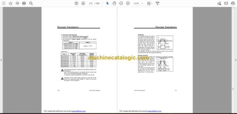
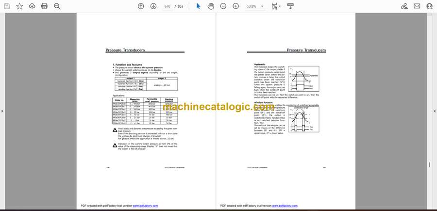
Pressure Transducer ………………………………………………………………………………………………… 8-23
Level Transducer ……………………………………………………………………………………………………… 8-23
Temperature Transducer ……………………………………………………………………………………………. 8-24
Water Flow Transducer ……………………………………………………………………………………………… 8-24
Inclinometers……………………………………………………………………………………………………………. 8-25
Head SpeedModule ………………………………………………………………………………………………….. 8-26
Level Switches …………………………………………………………………………………………………………. 8-27
Dust Suppression …………………………………………………………………………………………………….. 8-27
Turkey Spray ……………………………………………………………………………………………………………. 8-27
Water Suppression Tank Top Up …………………………………………………………………………………. 8-27
Vigilante System Component Information ………………………………………………………….. 8-28
Contents………………………………………………………………………………………………………………….. 8-28
Head Speed Module ………………………………………………………………………………………….. 8-29
Inclinometer ………………………………………………………………………………………………………. 8-31
Ladder Prox Switch …………………………………………………………………………………………… 8-34
Laser ………………………………………………………………………………………………………………… 8-35
Level Switches………………………………………………………………………………………………….. 8-47
Radiator Level Switch ……………………………………………………………………………………….. 8-51
Level Transducers …………………………………………………………………………………………….. 8-55
Pressure Transducers……………………………………………………………………………………….. 8-65
Temperature Transducer……………………………………………………………………………………. 8-74
Water Flow Transducer ……………………………………………………………………………………… 8-83
Water Control Module………………………………………………………………………………………… 8-97
Rod Counter Prox Switch ………………………………………………………………………………… 8-104
Remote Fuel Level Display ………………………………………………………………………………. 8-105
Section 9
Lubrication and Preventive Maintenance……………………………….. 9-1
Central Lube System…………………………………………………………………………………………… 9-2
Hydraulic Control Schematic………………………………………………………………………………………… 9-3
Auto Lube ………………………………………………………………………………………………………………….. 9-3
Central Lube System Circuit Drawing ………………………………………………………………….. 9-5
Central Lube Tank Assembly……………………………………………………………………………….. 9-6
Central Lube System…………………………………………………………………………………………… 9-7

