Format: PDF (Printable Document)
File Language: English
File Pages: 220
File Size: 16.66 MB (Speed Download Link)
Brand: Volvo
Model: ECR25 Electric Wheeled Excavator
Type of Document: Operator’s Manual
$ 45
Presentation
Intended use
Environmental requirements
Motor
Electrical system
Open Source Software
Cab
Hydraulic system
Equipment
Modifications
Travel system
Slewing system
Anti-theft device
(optional equipment)
CareTrack
(optional equipment)
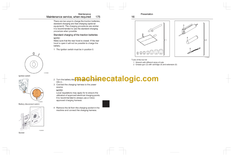
Tool kit
(optional equipment)
Machine view
CE-marking, EMC-directive
CE marking
EU EMC Directive
EU conformity certificate
Communication equipment, installation
Protection against electromagnetic interference
Guidelines for installing aerial
Safety components
Safety-classified machine and spare parts
Examples of safety-classified machine parts/spare parts
Product plates
1 Product Identification plate (PIN)/Supplementary PIN plate (EU countries only)
2 TOPS/ROPS and OPG plate
Information and warning decals
Instrument panels
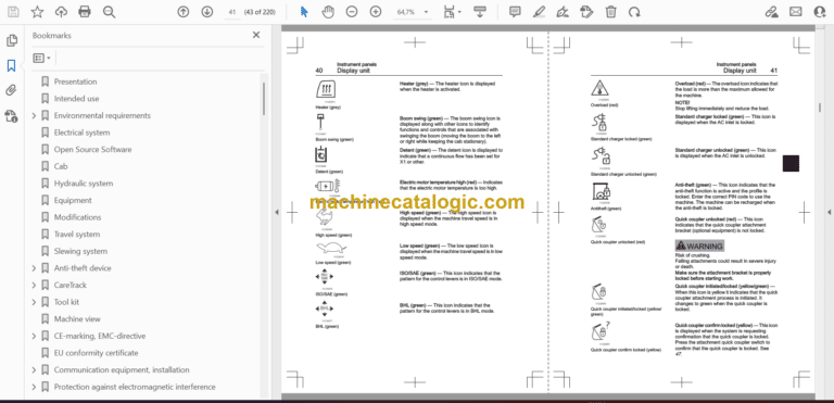
Display unit
Home screen
Keypad
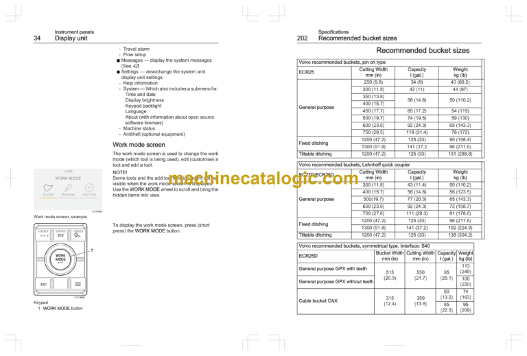
Work mode screen
Tool, set up or change settings
Tool, add to work mode
Antitheft screen
How to enter code
Failed attempts
Tool editor
Duplicate tool
Delete tool
Flow setup
Change tool image
Edit name
Indicator icons
System messages
Warning messages
Warning messages, full screen view
Caution messages
Caution messages, full screen view
Information messages
Information messages, full screen view
Message center
Dismissed messages
Day mode
Night mode
Instrument panel, right
1. Temperature control
2. Keypad
3. Ignition switch
4. Charging switch
5. Attachment quick coupler switch
6. Rotating warning beacon switch
7. Windscreen wiper and washer switch
8. Fan switch
Other controls
Controls
1. Left control lever for attachments (ISO/SAE control pattern)
Left control lever for attachments (BHL control pattern)
2. Proportional Roll switch to control X3 hydraulic flow (optional equipment)
Hydraulic oil flow, changing maximum setting for X3
3. Horn
4. Control lockout lever for working and travel
5. Control levers for travel motion
6. Right control lever for attachments (ISOSAE control pattern)
Right control lever for attachments (BHL control pattern)
Pattern change (optional equipment)
To change control pattern:
7. Push button for X1 max flow
8. Proportional roll switch or two buttons to control X1 or boom offset hydraulic flow
Flow adjust for X1 and X3 with WORK MODE wheel
9. Offset boom or X1 selection
10. Button to activate fast travel speed gear
11. Dozer blade control lever
ROPS
ROPS Cab (Roll Over Protective Structure)
Protection from falling or scattering materials (optional equipment)
OPG Level 1
OPG Level 2
Operator comfort
Operator seat
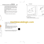
Operator’s seat, adjusting
Operator’s seat, option variant A
Operator’s seat, option variant B
Operator’s seat, option variant C
Seat belt
Power socket
Heater
Windows
Upper windscreen
Lower windscreen
Working lights
Door
Operator’s manual, storage
Fire extinguisher, location
Emergency exit
Audio system
Radio with USB, SD and Bluetooth
Operating instructions
Running-in instructions
Visibility
Mirror setting
Measures before and during operation
Safety rules when operating
Traction battery, charging
Standard charging of the traction batteries
Fast charging (DC) of the traction batteries
Operator obligations
Accidents
Operator safety
Stability when working
Operating on public roads
Periodic replacement of critical parts for safety
Measures before operating
Starting machine
Starting the Electric System
Stopping
Parking
Long-term parking
Check after long-term parking
Retrieving and towing
Towing
Attachments, alternative lowering
Lowering attachment using accumulator pressure
Relieving residual pressure from the accumulator
Lowering attachment in case of problems with the electric circuit
Transporting machine
Measurements before transporting machine
Weight and dimension
Tying down machine
Cross tie down procedure
Tying down on small trailer (3.5 t)
Tying down on truck
Lifting machine
Loading machine on truck or trailer
Unloading machine
Operating techniques
Eco driving
Whole-body vibrations
Guidelines for reducing vibration levels on earthmoving machines
Rules for digging
Working within dangerous areas
High voltage overhead power line
Overhead railway power lines
Underground cables and pipes
Working on slopes
Caution on slopes
Working in water and on boggy ground
Working where there is risk of landslip
Working in cold weather
Demolition work
Attachments
Attachments, connecting and disconnecting
Installing a bucket with manual fastening
Attachment brackets
Volvo Attachment bracket
Mechanical attachment bracket, bucket installation
Hydraulic attachment bracket
Attachment quick coupler
Disconnecting & connecting a bucket
Pressure release
Buckets
Working with buckets
Backhoe work
Ditching work
Loading work
Backfilling or grading
Offset boom
Boom offset function, settings
Special hydraulics
Hammer
Working with hammer
(hydraulic breaker)
Connecting with pivot pins
Disconnecting with pivot pins
Connecting to an attachment bracket
Hose rupture valves
(optional equipment)
Tracks
When using rubber tracks
Moving over obstacles
Lifting objects
Stability
Fastening long lifting slings
Lifting capacities
Signalling diagram
Safety when servicing
Service position
Before service, read
Prevent personal injuries
Prevent machine damage
Prevent environmental impact
Entering, leaving and climbing the machine
Entering, leaving and climbing the machine
Access to cab
Leaving cab
Alternative exit path
Fire prevention
Fire prevention measures
Actions in case of fire
Actions after fire
Handling hazardous materials
Heated paint
Heated rubber and plastics
Heated fluoro-carbon rubber
Service battery
Traction battery
Crystalline silica (quartz) dust
Handling line, tubes and hoses
Maintenance
Service history
Arrival Inspection
Delivery Inspection
Delivery Instructions
Service Programme
Lubrication and service chart
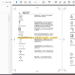
Symbol key
Maintenance service, every 10 hours
Test-run and check
Warning decals
External check
Lights, instruments, and controls
Hydraulic oil level, checking
Maintenance service, every 50 hours
Bearings, greasing
High voltage components condition, visual checking
Maintenance service, every 250 hours
Track unit, checking tension
Service battery, checking
Maintenance service, every 500 hours
Coolers, cleaning
Maintenance service, when required
Service battery, charging
Traction battery, charging
Standard charging of the traction batteries
Fast charging (DC) of the traction batteries
Welding
Cleaning machine
Paint finish maintenance
Touch-up painting
Battery and service compartment, cleaning
Washer reservoir
Front windscreen rails
Bucket and ripper teeth, replacing
Removing bucket tooth
Removing ripper tooth
Installing tooth
Recommended intervals for critical parts
Maintenance under special environmental conditions
Specifications
Recommended lubricants
Hydraulic oil
Service capacities and change intervals
Change capacities
Change intervals
Electrical system
Relays and fuses, 12V
Relays
Fuses
Cab
Sound information
Hydraulic system
Hydraulic system
Specifications
Transmission
Slewing system
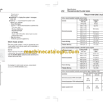
Machine weights
Machine weights
Ground pressure
Dimensions
Working ranges
Recommended bucket sizes
Digging forces
Lifting capacities
Lifting capacities ECR25, Cab, with safety valves on dipper arm and boom (not on dozer blade)
Lifting capacities ECR25, Cab, with safety valves on dipper arm, boom and dozer blade
Hammer (hydraulic breaker)
Hydraulic breaker
Hammer tools
Service history
Alphabetical index