Format: PDF (Printable Document)
File Language: English
File Pages: 432
File Size: 40.99 MB (Speed Download Link)
Brand: Volvo
Model: EWR150E, EWR170E Wheeled Excavator
Type of Document: Operator’s Manual
$ 45
Identification numbers
Presentation
Intended use
Environmental requirements
Engine
AdBlue®/DEF information
Exhaust aftertreatment system
Electrical system
Relays and fuses
Brake system
Service brakes
Digging brake
Parking brake
Steering system
Cab
Hydraulic system
Equipment
Modifications
Swing drive unit
CareTrack/Information Systems
Tool kit
(optional equipment)
Toolbox content
Machine view
CE-marking, EMC-directive
CE marking
EU EMC Directive
EU conformity certificate
Communication equipment, installation
Protection against electromagnetic interference
Guidelines
Safety components
Safety-classified machine and spare parts
Examples of safety-classified machine parts/spare parts
Product plates
Product plate
Engine product plate
Travel gearbox product plate
Axle product plate
Information and warning decals
EWR150E Korea only:
Instrument panels
Instrument panel, left
1. Control lockout lever
2. Cab interior light switch
3. Trailer flashing indicator (optional equipment)
4. Control lever for stabiliser legs / stabiliser blade / dump trailer
(only without joystick controlled support)
5. Unassigned / depending on options
6. Unassigned / depending on options
7A. Left control lever / 7B. L8–5 Left control lever
8. Attachment quick coupler confirmation switch
9. Unassigned / depending on options
10. Trailer lifting activation switch (optional equipment)
11. Unassigned / depending on options
12. Unassigned / depending on options
Instrument panel, front
New information top bar (only if new camera function is installed)
Central warning light
Gauges
Time and engine speed
Mode
CCM (Climate Control Module)
Indicators
Display unit
Start sequence
Camera screen
Alarm texts
Results / Function description
Results
Function description
Main menu
Subscreens
Engine
Hydraulics
Electrical system
Vehicle information
Service
Setup
Vehicle messages
Setups
X1 work tool
X3 Operation
CDC steering speed
Tiltrotator setup
Auto idle time
Joystick shortkey (Multi function button)
Language
Units
Time/Date
Display light
Keypad backlight
CareTrack with anti-theft
CareTrack with anti-theft (optional equipment)
Anti-theft system, setup menu
Alarm texts for anti-theft system
Control types for X1 and X3 operation
Proportional control levers (Sliding switches)
L8–5 control levers
Instrument panel, right
1. Rotating warning beacon switch (optional equipment)
2. Travel speed selection switch
3A. Right control lever
3B. Right control lever (L8-5 control lever)
4. Comfort Drive Control (CDC) activation switch
5. Grapple changeover (optional equipment)
6. Boom suspension system (BSS) (optional equipment)
7. Electric digging brake (optional equipment)
8. Cigarette lighter (optional equipment)
9. Axle lock and cruise control switch (optional equipment)
10. Light control switch
11. Attachment quick coupler switch (optional equipment)
12. IC (Instrument Cluster) control keypad
13. Machine control keypad
14. Mode selector control
15. Audio remote control
16. Ignition switch
17. Power outlet 12V
18. Drink and cup holder
19. Hour meter
(placed on the right hand panel in the cabin)
20. Hazard flasher switch
(placed under the steering wheel)
Instrument panel, rear
Instrument panel, rear
Other controls
Controls
1. Left control lever
2. Right control lever
3. Steering wheel
4. Multi-function lever
5. Pedal for X1 (optional equipment)
6. Pedal for offset boom (optional equipment)
7. Service brake pedal with toggle lever for brake lock (digging brake)
7. Electric digging brake (optional equipment)
8. Travel pedal
9. Steering wheel adjustment
Control levers, description
1. Left control lever with SAE (ISO)
Swing brake
2. Right control lever with SAE (ISO)
Changing machine control pattern
(optional equipment)
Control levers: buttons and proportional switches
X3 control, description
X1 control, description
Tiltrotator control system, description
(optional equipment)
Controls
Cab
ROPS (Roll Over Protective Structure)
Protection from falling or scattering materials (optional equipment)
Anti-vandal kit (optional equipment)
Control lockout system
Automatic engine shut down
Operator comfort
Remote welcome lights
(optional equipment — only in combination with LED working lights)
Operator seat
Mechanical suspension seat
Air suspension seat (optional equipment)
Deluxe seat (optional equipment)
Left armrest position when entering the cab or leaving it
Special features
Seat belt
Green light (seatbelt indicator)
(optional equipment)
Climate control system
HVAC system (Heating, Ventilation, Air Conditioning)
HVAC setup
Windows
Open the upper front window
Close the upper front window
Removing the lower front window
Door
Sun shade
Rain shield
Roof
Roof hatch, open (optional equipment)
Storage compartment
Cup and drink holder
Ashtray (optional equipment)
Coat hook
Operator’s manual, storage
Fire extinguisher, location
Emergency exit
Audio system
(optional equipment)
Radio and USB-MP3 Player (with bluetooth)
Vision system
Camera system
New camera function (if installed on the machine):
Camera views
Rear view camera
Side view camera
Volvo Smart View
(Optional equipment)
If the new camera function is installed: The camera screen in the IC (Instrument Cluster) is always shown if any condition of below is met
View logic — single view
Split view configuration
Split-view setting
Shortkey (multifunctions) button on control lever
CAB auxiliary heater, description
(Optional equipment)
Check which of the two auxiliary heater control unit versions is installed in your machine.
Operation and setting/adjustment
Other possible actions are:
The following actions are possible during the heating off display:
Example:
Error messages
CAB auxiliary heater, description
Operating instructions
Running-in instructions
Visibility
Mirror and camera settings
Measures before and during operation
Safety rules when operating
Operator obligations
Operator obligations — risk of fire
Operator obligations — risk of high pressure injection
Accidents
Operator safety
Operating on public roads
Travelling on public roads
Travelling with grab bucket (clamshell bucket)
Travelling on uneven ground
Align the superstructure with the undercarriage
Cruise control (optional equipment)
Pivot axle locking
Automatic pivot axle locking
Manual pivot axle locking
Measures before operating
Starting engine
Starting engine in cold weather
Engine block heater
(optional equipment)
Starting with booster batteries
Follow these steps:
Turbocharger
Hydraulic system, warming up
Travelling a short distance
Operating
Steering
Speed
Mode selection
Travelling speed
Steering
Steering
Driving direction (Forward/Neutral/Rearward)
Comfort Drive Control (CDC)
(optional equipment)
CDC control lever steering
CDC activation
CDC active at machine start
CDC display messages
CDC steering speed
Braking
Service brake
Parking brake
Toggle lever for brake lock (digging brake)
Electric digging brake
(optional equipment)
Exhaust aftertreatment system
Regeneration
Normal operation
Parked regeneration
Service regeneration
Fuel consumption
Delaying regeneration
Possible consequences of delaying regeneration:
Cancelling parked regeneration
Emission compliance
Engine power is reduced if:
Exhaust aftertreatment system, alarms requiring special actions
Stopping
Stopping
Parking
Long-term parking
Checks after long-term parking
Retrieving and towing
Parking brake, mechanical release
Activate emergency actuation on gearbox
Deactivate emergency actuation on gearbox
Pivot axle lock cylinder, manual release for towing
Releasing axle lock cylinders manually
Attachments, alternative lowering
Alternative lowering with servo pressure
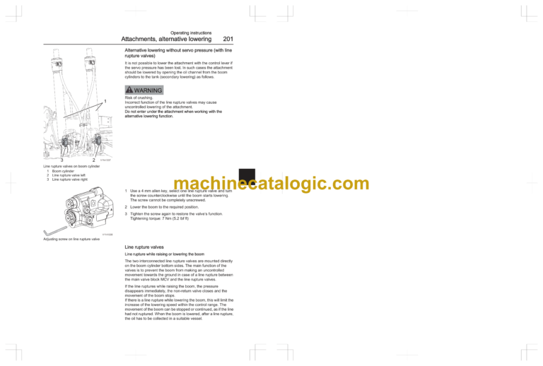
Alternative lowering without servo pressure (with line rupture valves)
Line rupture valves
Transporting machine
Measurements before transporting machine
Tying down machine
Lifting machine
Operating techniques
Eco driving
ECO mode function
Operating behaviour
Whole-body vibrations
Guidelines for reducing vibration levels on earthmoving machines
Rules for digging
While working, do not:
Loading on to a vehicle
Boom Suspension System (BSS)
Boom Suspension System (BSS)
(Suspension of digging equipment / optional equipment)
Engaging the boom suspension system
Travel position with BSS
Disengaging the boom suspension system
Working within dangerous areas
High voltage overhead power line
Railroad overhead contact system
Underground cables and pipes
Working on slopes
Working in water and on boggy ground
Working where there is risk of landslip
Working in cold weather
Demolition work
Reversible fan
Attachments
Tiltrotator control system, description
Operating
Installing the tiltrotator
Removing the tiltrotator
Tiltrotator control system, description
Operating full hydraulic quick coupler (SQ-type) in combination with tiltrotator.
Installing the tiltrotator SQ-type or an attachment with an SQ adapter plate
Removing the tiltrotator SQ-type or an attachment with an SQ adapter plate
Attachments, connecting and disconnecting
Attachment quick coupler
Lifting hook
Attachment quick coupler, S60
S60 attachment quick coupler (optional equipment)
Indicator pin S60
Connecting attachment
Disconnecting attachment
Attachment quick coupler, SQ-type
Full hydraulic quick coupler, SQ-type (optional equipment)
Indicator pin
Connecting attachment
Disconnecting attachment
Specification table for full hydraulic quick couplers
Attachment quick coupler, S6
S6 attachment quick coupler (optional equipment)
Lifting hook
Indicator pin
Connecting and disconnecting attachment
Attachment quick coupler, S1
S1 attachment quick coupler (optional equipment)
Indicator pin
Connecting and disconnecting attachment
S1 attachment bracket (quickfit) , adjusting
Adjusting — New version of the S1
Adjusting — Former version of the S1
Universal attachment quick coupler
Universal attachment quick coupler (optional equipment)
Lifting eye
Connecting attachment — universal attachment quick coupler
Disconnecting — universal attachment quick coupler
Maintenance — universal attachment quick coupler
Pressure release
Hydraulic system, releasing pressure
Hydraulic couplings
Hydraulic couplings
Buckets
Working with buckets
Float position
Power Boost
Changing bucket
Remove bucket
Install bucket
Grab bucket
(Clamshell bucket)
Operating a grab bucket — with grapple bucket changeover function (optional equipment) activated:
Operating a grab bucket — without grapple bucket changeover function:
Attaching grab bucket
Disconnecting grab bucket
Tiltable ditching & grading bucket
Safety
Safety rules for operating with the tiltable ditching and grading bucket:
Operating instructions
First use
Operating
Attachments, connecting and disconnecting
Connecting to hydraulic circuit
Disconnecting from hydraulic circuit
Lifting points
Maintenance
Bucket cylinder grapple lines
Offset boom
Mono-block offset boom
(Optional equipment)
Two-piece offset boom
(optional equipment)
Hammer
Hammer/shear
Working with hammer
Lifting objects
Stability
Slinging long loads
Lifting hook
Lifting device on connecting rod (optional equipment)
Transporting load
Overload warning
Overload warning system, checking
Equipment towing
Trailer towing solution (TTS)
(optional equipment)
Install and remove trailer hitch on blade
Install and remove trailer hitch on outrigger
Maintenance
Hitching and unhitching a trailer
Specification table for trailer towing
Signalling diagram
Safety when servicing
Service position
Service positions
Before service, read
Preventing personal injury
Preventing machine damage
Preventing environmental influence
Battery disconnect switch
Electrical system
Electrical distribution box
Hydraulic system
Hydraulic oil
Entering, leaving and climbing the machine
Entering, leaving and climbing the machine
Climbing on the machine:
Fire prevention
Fire prevention measures
Actions in case of fire
Actions after fire
Handling hazardous materials
Heated paint
Heated rubber and plastics
Heated fluoro-carbon rubber
Crystalline silica (quartz) dust
Batteries
Refrigerant
Environmental precautions
Safety precautions
Actions in case of exposure
Handling line, tubes and hoses
Maintenance
Lubrication and service chart
Service history
Arrival Inspection
Delivery Inspection
Delivery Instructions
Service Programme
Service points
Lubrication and service chart
Lubrication
Lubrication has two main purposes:
Symbol key
Lubrication and service chart
Maintenance service, every 10 hours
Test-run and check
Decals, plates and reflectors
External check
Test-run
Leakage, checking
Washer reservoir
Excavator unit, greasing
Remote greasing nipples
Maintenance service, every 50 hours
Tyres, wear and air pressure, checking
Hydraulic oil level, checking
Hydraulic tank, draining
Excavator unit, greasing
Arm
Boom
Quick coupler (optional equipment)
Excavator unit, greasing
Tiltable ditching & grading bucket
Attachments pin/ball, greasing
Remote greasing nipples
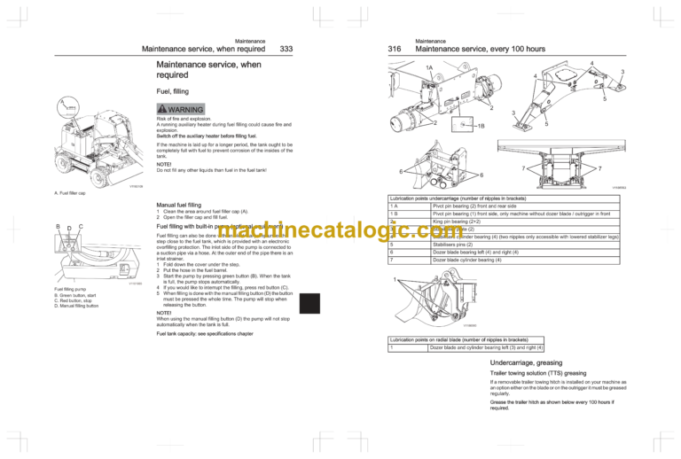
Maintenance service, every 100 hours
Undercarriage, greasing
Undercarriage, greasing
Trailer towing solution (TTS) greasing
Trailer hitch for drawbar eye 40 mm
Trailer hitch for drawbar eye 50 mm
Greasing of trailer hitch bolt or plug for blade and on blade
Greasing after cleaning with pressure washer
Maintenance
Maintenance service, every 250 hours
Engine oil level, checking
Level checking
Engine oil, draining
Coolant level, checking
Coolant, draining
Travel gearbox oil level, checking
Axles, checking oil level
Axles, checking oil level
Axle hubs, checking oil level
Cab prefilter, cleaning and replacing
Maintenance service, every 500 hours
Cab door hinges, greasing
Battery, checking
Cab main filter, cleaning
Intercooler, radiator, hydraulic oil cooler, cleaning
Attachment quick coupler
(optional equipment)
Maintenance service, every 1000 hours
Wheel nuts, checking tightening
Overload warning
Maintenance service, every 2000 hours
Coolant
Maintenance service, when required
Fuel, filling
Manual fuel filling
Fuel filling with built-in pump (optional equipment)
AdBlue®/DEF, filling
AdBlue®/DEF tank, draining
Water separator, draining
Fuel system, bleeding
Fuel tank, draining
Batteries, charging
Welding
Headlights, adjusting
Cleaning machine
Paint finish maintenance
Touch-up painting
Cleaning engine compartment
Engine air cleaner
Engine air cleaner primary filter, cleaning and replacing
Cleaning or replacing the primary filter
Engine air cleaner secondary filter, replacing
Bucket teeth, replacing
For Volvo tooth system I (VTS)
Removing tooth
Installing tooth
Bucket teeth, replacing
For Volvo tooth system II (VTS)
Removing tooth
Installing tooth
Hydraulic system, releasing pressure
Accumulator, handling
Accumulator, emergency operation
Accumulator, pressure releasing
Automatic lubrication system
(optional equipment)
Lubrication unit
Additional lubrication
Cycle switch
Grease filling
Maintenance service, general
Manually greasing in case of pump failure
Recommended intervals for critical parts
Maintenance under special environmental conditions
Specifications
Recommended lubricants
Recommended lubricants
Oils and lubricants
Engine oil
Hydraulic oil
Axle oil
Travel gearbox
Grease
Coolant
Fuel system
Fuel
Alternative fuels
Hydro-treated vegetable oil (HVO)
Biodiesel
Biodiesel fuel requirements
Maintenance interval requirements
Effects of biodiesel on engine oil
Effects of biodiesel on fuel systems
Effects of biodiesel on exhaust aftertreatment systems
Effects of biodiesel on cold weather operation
Effects of biodiesel on engine performance
Effects of biodiesel on emissions compliance
AdBlue®/DEF
Service capacities and change intervals
Oil and fluid change, intervals
Filter change, intervals
Oils and other liquids
EWR150E
EWR170E
Engine
Electrical system
Relays and fuses
Relays and fuses
Wheels
Tyre sizes and pressures
Wheel nuts, tightening torque
Cab
Operator seat
Refrigerant
Noise and vibrations
Hand-arm vibrations
Whole-body vibrations
Sound information
Hydraulic system
Machine weights
EWR150E
EWR170E
Dimensions
EWR150E
EWR150E with bolt-on undercarriage
EWR150E with weld-on undercarriage
EWR170E
Working ranges
EWR150E
EWR170E
Recommended bucket sizes
EWR150E
EWR170E
Digging forces
Digging forces
EWR150E
with direct mounted bucket (V4_GP)
EWR170E
with direct mounted bucket (V4_GP)
Lifting capacities
EWR150E: 4.7 m Two-piece boom, bolted dozer blade front and outriggers rear
EWR150E: 4.7 m Two-piece boom, bolted dozer blade rear only
EWR150E: 4.5 m Monoblock boom, bolted dozer blade front and outriggers rear
EWR150E: 4.5 m Monoblock boom, bolted dozer blade rear only
EWR150E: 4.75 m Monoblock offset boom, bolted dozer blade front and outriggers rear
EWR150E: 4.75 m Monoblock offset boom, bolted dozer blade rear only
EWR150E: 4.7 m Two-piece boom, welded radial dozer blade front and outriggers rear
EWR150E: 4.7 m Two-piece boom, welded radial dozer blade rear only
EWR150E: 4.5 m Monoblock boom, welded radial dozer blade front and outriggers rear
EWR150E: 4.5 m Monoblock boom, welded radial dozer blade rear only
EWR150E: 4.75 m Monoblock offset boom, welded radial dozer blade front and outriggers rear
EWR150E: 4.75 m Monoblock offset boom, welded radial dozer blade rear only
EWR170E
EWR170E: 5.1m (16 ft 8.8 in) Two-piece boom, blade front and outriggers rear
EWR170E: 5.1m (16 ft 8.8 in) Two-piece boom, blade rear only
EWR170E: 5.1m (16 ft 8.8 in) Two-piece offset boom, blade front and outriggers rear
EWR170E: 5.1m (16 ft 8.8 in) Two-piece offset boom, blade rear only
Service history
Alphabetical index