Format: PDF (Printable Document)
File Language: English
File Pages: 483
File Size: 91.78 MB (Speed Download Link)
Brand: Volvo
Model: L120C BM Wheel Loader
Type of Document: Service & Repair Manual
$ 45
(0) GENERAL
Brakes
Capacities and weights (2)
Capacities and weights
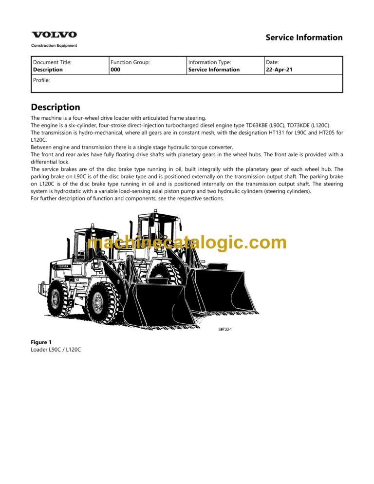
Description
E 1664 Lifting tool
E 1666 Spanner
E1752 Lifting yoke
Engine
E-tools
Hydraulic system
Power transmission
Product identification plates
Standard tightening torques (2)
Standard tightening torques
Steering
Tightening torques (2)
Tightening torques
Time Guide
(1) STANDARD PARTS, SERVICE
Cleanliness when working on hydraulic systems
Electric welding
Repairing hydraulic system
Towing
(2) ENGINE WITH MOUNTING AND EQUIPMENT
Air cleaner, specifications
Checking speed with multimeter
Cold-starting control, specifications
Description
Engine, fitting
Engine, removing
Feed pump, checking feed pressure TD40KAE
Fuel system, air bleeding TD40 KAE, TD40 GFE
Fuel system, air bleeding TD40GA
Fuel tank and combined tank unit, changing
Fuel tank, specifications
Injection pump, fitting and adjusting injection timing, TD40KAE
Injection pump, fitting, TD40GFE
Injection pump, removing TD40GFE
Injection pump, removing, TD40KAE
Injection pump, specifications
Injection timing adjustment at low engine temp., TD40GFE
Injection timing, checking and adjusting, TD40GA
Injection timing, checking and adjusting, TD40KAE
Injectors and delivery pipes, specifications
Intercooler, specifications
Low and high idling speed, checking and adjusting
Specifications (2)
Specifications (3)
Specifications (4)
Specifications (5)
Specifications, coolant pump and thermostat
Specifications
Turbocharger, specifications
Valves, adjusting
(3) ELEC. SYSTEM, WARNING SYSTEM, INFORMATION SYSTEM, INSTRUMENTS
Battery, charging
Code key for diodes (2)
Code key for diodes
Codes used in wiring diagrams
Control unit BCU
Control unit ECU
Electrical distribution box
Explanations of wiring diagrams,
General description
Headlights, adjusting
Instruments and controls
Limp-Home operation, by-passing control units
List of circuits
Menu overview, service display unit
Monitored functions ECU
Other electrical functions controlled by the control unit, ECU
Service display unit
Special instructions when working on the electrical system
Specifications (2)
Specifications (3)
Specifications (4)
Specifications (5)
Specifications (6)
Specifications
Units connected to control unit BCU
Units connected to control unit ECU
WIRING~1
Wiring diagram 1. Main diagram BCU
Wiring diagram 1B. Main diagram ECU
Wiring diagram 1C. Main diagram Limp-Home operation ECU
Wiring diagram 2. BCU
Wiring diagram 2B. ECU
Wiring diagram 2D. Intermittent wiper BCU
Wiring diagram 3. Gear shifting BCU
Wiring diagram 3B. Gear shifting ECU
Wiring diagram 3C. Limp-Home opn. ECU
Wiring diagram 4. Gear shift solenoids ECU
Wiring diagram 5. Engine TD40GA, TD40GFE
Wiring diagram 5D. Engine TD40KAE
Wiring diagram 5D. Preheating engine TD40KAE. W.e.fr. serial number 11233
Wiring diagram 6. Hydraulics
WIEC5D~1
Wiring diagram 7B. Secondary steering ECU
Wiring diagram 7C. Secondary steering with ECU by-passed
Wiring diagram 8. Pressure draining, brake pressure charging,
Wiring diagram 8D. Brake pressure charging, attachment locking
Wiring diagram 9. Travel lights
Wiring diagram 10. Working lights, rotating warning beacon
Wiring diagram 11. Stop lights, direction indicators, hazard flashers
Wiring diagram 12. Radio, heated seat
Wiring diagram 13. Instruments, sensors BCU
Wiring diagram 13B. Instr, sensors ECU
Wiring diagram 13C. Instruments, sensors ECU during Limp-Home operation
Wiring diagram 14. Instr., alternator BCU
Wiring diagram 14B. Instr., alternator ECU
Wiring diagram 14C. Instruments, alternator ECU during Limp-Home operation
Wiring diagram 15. Dual control ForwardReverse BCU
Wiring diagram 15B. Dual control ForwardReverse ECU
Wiring diagram 15C. Dual control ForwardReverse during Limp-Home operation ECU
Wiring diagram 15D. Single lever control
Wiring diagram 16. Air conditioning (AC)
Wiring diagram 17. Service display unit
Wiring diagram 18. Boom Susp. System (BSS)
Wiring diagram 19. Mechanical parking brake with Rider truck safety norm
Wiring diagram 19D. Hydraulic parking brake
Wiring diagram 20B. Lever steering (CDC) w. adjust. ramp gen. Up to and incl. sn 10631
Wiring diagram 20B. Lever steering (CDC) w. non-adjust ramp gen. W.e.fr. sn 10632
Wiring diagram 21. 4th hydraulic function, activation
Wiring diagram 21D. 4th hydraulic function, activation
Wiring diagram 22. 4th hydraulic function,
Wiring diagram 23. 3rd hydraulic function
Wiring diagram 25. 5th and 6th hydr. function
Wiring diagram 26. Automatic greasing
Wiring diagram 27. Automatic greasing with
Wiring diagram 28. Mechanical and hydraulic
Wiring diagram 28B. Mechanical and hydraulic parking brake with ECU
(4) POWER TRANSMISSION
Axle, installing
Axle, removing
Clutch shaft, high-gear
Clutch shaft, low-gear
Description
Differential carrier assembly, front axle
Gearbox, checking oil pressure
Gearbox, installing
Gearbox, removing
Gearbox, sectional view
Hydrostatic pump, removing and fitting
Hydrostatic system, checking oil pressure
Hydrostatic system, neutral position
Obligatory measures when repairing the hydrostatic system
Planetary gear
Rear axle suspension
(5) BRAKE
Brake discs, checking wear (with built-in wear indicator)
Brake discs, checking wear (without built-in wear indicator)
Brake discs, replacing
Brake system, checking and adjusting pressure in circuit
Description (2)
Description of function
Description
Foot brake valve (removed), reconditioning
Foot brake valve, description of function
Functional check
Hydraulic diagram, brake system
Parking brake, adjusting
Retardation, functional check
(6) STEERING
Description
Hydraulic diagram, lever steering CDC Basic Machine
Hydraulic diagram, steering system Basic Machine
Hydraulic pump, description
Steering cylinder, reconditioning
Steering cylinder, replacing
Steering cylinder, sectional view
Steering pressure and stand-by pressure, checking and adjusting
Steering valve, description
Steering valve, reconditioning
(7) FRAME, SPRINGS, DAMPING, AXLE SUSPENION, WHEEL TRACK UNIT
Axle suspension, checking axial and radial clearance
Frame joint bearing, lower, sectional view
Frame joint bearing, upper, sectional view
Frame joint, replacing bearings
General description
(8) MACHINERY HOUSE, CAB, EXTERIOR TRIM PARTS ANYWHERE
AC SAFETY, description of function
Description (2)
Description
Electrical system, description of function
(9) HYDRAULIC SYSTEM, DIGGING, HANDLING, GRADING EQUIPM, MISC. EQUIP
3rd function, flow control
4th hydraulic function, description
4th hydraulic function, wiring diagram
5th6th hydraulic functions and attachment
5th6th hydraulic functions, adjusting speed flow
5th6th hydraulic functions, basic adjustment of speedflow
5th6th hydraulic functions, description
5th6th hydraulic functions, draining the quick-action couplings
5th6th hydraulic functions, electrical functions.
5th6th hydraulic functions, monitoring function, checking
5th6th hydraulic functions, wiring diagram
Accumulator, Boom Suspension System,
Attachment hydraulics GP, description
Attachment hydraulics GP, wiring diagram
Boom Suspension System, description
Boom Suspension System, hydraulic diagram
Boom Suspension System, safety valve, checking, adjusting
Boom Suspension System, wiring diagram
Control valve, description
Hydraulic diagram basic machine, 3rd4th, (2)
Hydraulic diagram basic machine, 3rd4th,
Hydraulic diagram, basic machine
Hydraulic oil pump, removing and fitting
Lifting arm, replacing bearings “A”
Lifting cylinder, replacing
Lifting cylinder, sectional view
Lifting frame, replacing bearings “B”
Servo pressure, checking and adjusting
Servo valve, description
Shock valve, lifting function, checking and adjusting
Shock valve, tilting function, checking and adjusting
Stand-by pressure, checking and adjusting
T link, upper, removed, replacing bearings “HIJ”
Tilting arm, replacing bearings “GDF”
Tilting cylinder, replacing
Tilting cylinder, sectional view
T-link, lower, removed, replacing bearings “GH”
Working hydraulics, description
Working pressure, checking and adjusting