Format: PDF (Printable Document)
File Language: English
File Pages: 978
File Size: 78.60 MB (Speed Download Link)
Brand: Wacker Neuson
Model: 2706, KT276 Telehandlers
Type of Document: System Handbook
$ 45
System Handbook
E Introduction
E.1 About this System Manual
E.2 Tightening torques
E.3 Safety instructions
2 Engine
2.1 Specifications, overview of nameplates
2.2 Cylinder numbering
2.3 Diesel engine overview
2.4 Lube oil system
2.5 Fuel system
2.6 Cooling system
2.7 Intake and exhaust system
2.8 Electric components
2.9 Exhaust after-treatment EAT
2.10 Start diesel engine control
2.11 Control of monitoring for diesel engine
3 Cooling
3.1 Cooling control
4 Power train
4.1 Assemblies
4.2 Checking and making adjustments
4.3 Adjustment work
4.4 Error descriptions
4.5 Travelling drive control
6 Brakes
6.1 Functional characteristics of brakes
6.2 Brake components
6.3 Test report for brake system
6.4 Service brake control
6.5 Hydraulic trailer brake
6.6 Safety instructions for hydraulic trailer brake
7 Steering
7.1 Function description: steering system
7.2 Test report: steering
7.3 Set steering cylinder
7.4 Steering system control
7.5 Description of steering components
7.6 Steering system components
8 Hydraulics
8.1 Functional characteristics
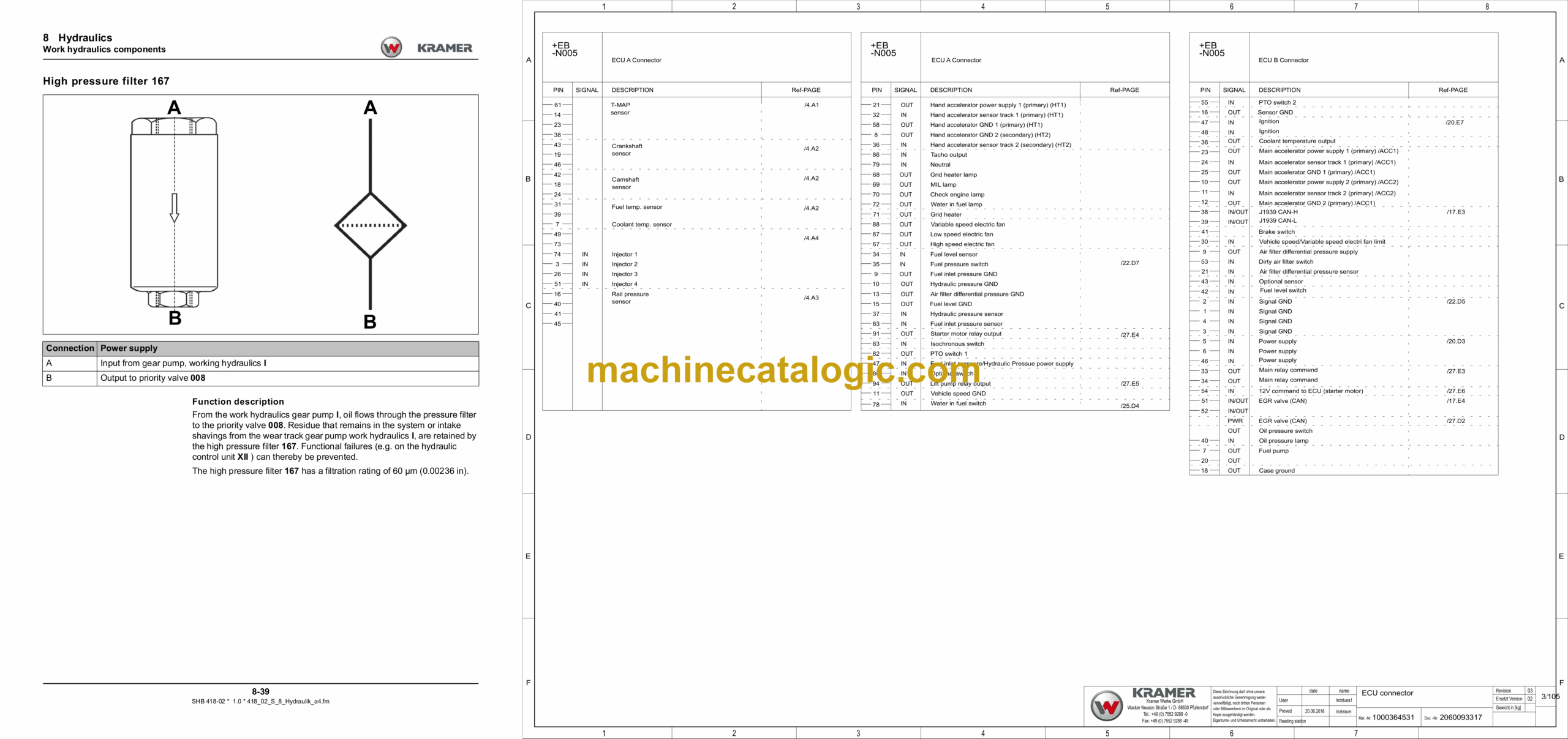
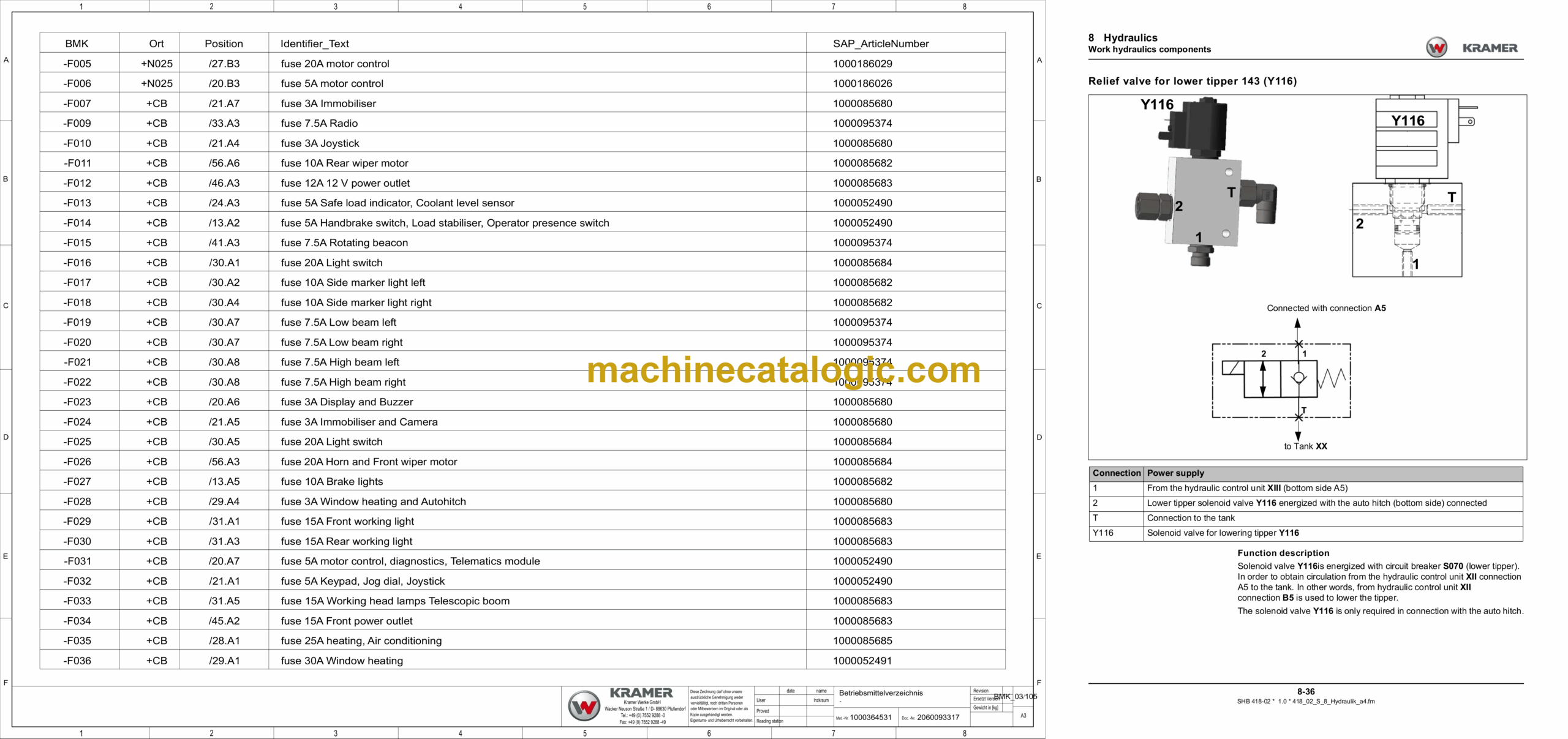
8.2 Work hydraulics components
8.3 Work hydraulics test report
8.4 Checking and making adjustments
8.5 Raising/lowering boom with load stabiliser
8.6 Control of tipping cylinder/tipping cylinder lock
8.7 Bucket repositioning control
8.8 3rd control circuit (control)
8.9 Reversing valve of third control circuit
8.10 Control of tipper and rear additional control circuit
8.11 Control of the rear auto hitch/tipper/additional control circuit
8.12 Sensor plate adjustment
8.13 Overload limiter (SMART HANDLING)
8.14 Hydraulic diagrams
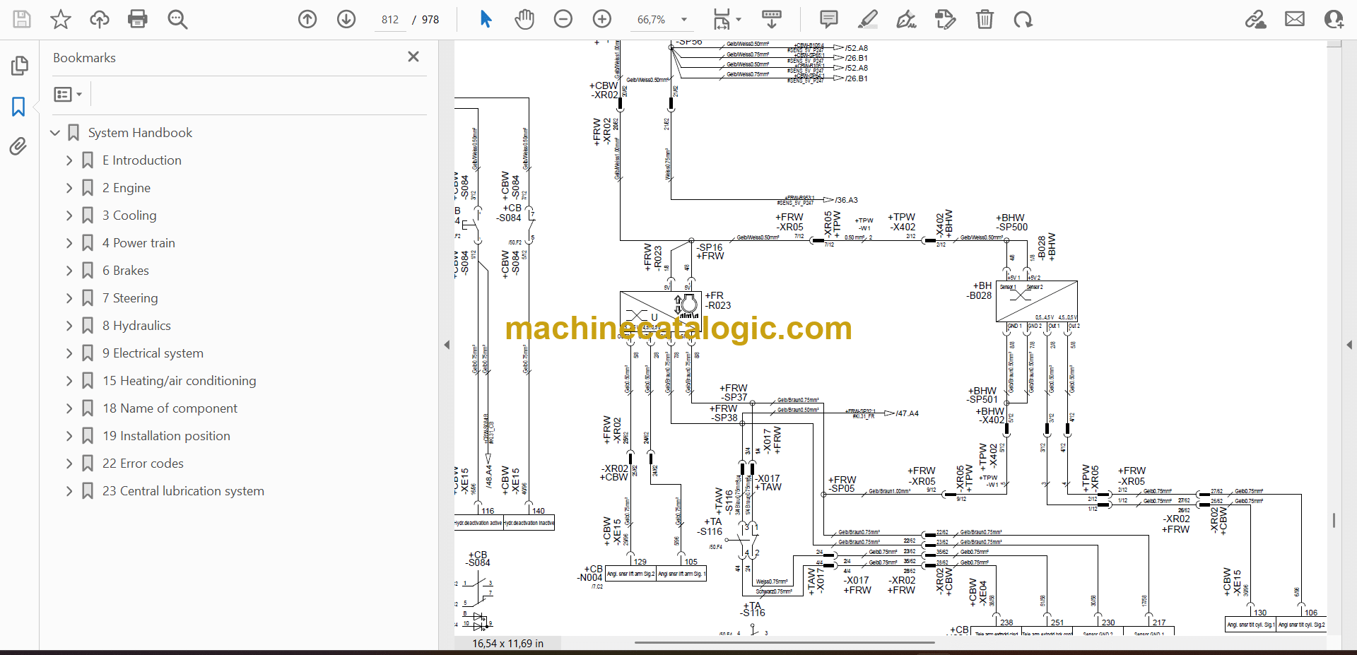
9 Electrical system
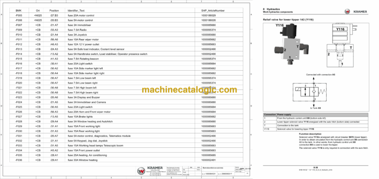
9.1 Fuses, relay
9.2 CAN signals
9.3 Description of CAN signal
9.4 In/outputs of traction electronics
9.5 Inputs/outputs controller N004
9.6 Inputs/outputs for diesel engine electronics N005
9.7 Control of telematics
9.8 Control of drive interlock N021
9.9 Control of 14-pole front socket
9.10 Control of 7-pole front socket
9.11 Control of 7-pole rear socket
9.12 Joystick control
9.13 Control of safe load indicator P006
9.14 Adjusting the safe load indicator P006
9.15 Load sensor B008
9.16 Setting the position pickup B028
9.17 Setting the rotary angle sensor R023
9.18 Inputs for indicating instrument P014
9.19 Camera (option)
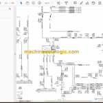
9.20 Diagrams
15 Heating/air conditioning
15.1 Control of heater/air-conditioning system
18 Name of component
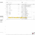
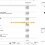
18.1 Designation of electrical components
19 Installation position
19.1 Hydraulic system installation position
19.2 Installation position of electrics
22 Error codes
22.1 Error code drive interlock N021
22.2 Error codes for safe load indicator P006
22.3 Cab electronics error code
22.4 Error code drive electronics N001
22.5 Error code for diesel engine electronics N005
22.6 Error code of 14-pole front socket electronics
23 Central lubrication system
23.1 Central lubrication system
23.2 Central lubrication system: Lubrication plan
23.3 Central lubrication system: Lubrication points

