Format: PDF (Printable Document)
File Language: English
File Pages: 262
File Size: 20.10 MB (Speed Download Link)
Brand: Wacker Neuson
Model: 50Z3 Tracked Excavator
Type of Document: Service Manual
$ 45
1 Operation
1.1 Information on this service manual
1.2 Identification of warnings and dangers
1.3 Designated use and exemption from liability
1.4 Type labels and component numbers
1.5 Machine overview
1.6 Cabin overview
1.7 Cabin (legend)
1.8 Instrument panel up to serial no. AC02877 (overview)
1.9 Instrument panel up to serial no. AC02877 (legend)
1.10 Instrument panel serial nos. AC02893 to AD07125 (overview)
1.11 Instrument panel serial nos. AC02893 to AD07125 (legend)
1.12 Control elements 50Z3 (from serial no. AH00579)
1.13 Engine compartment up to serial no. AD07125 (overview)
1.14 Engine compartment (from serial no. AH00579) (overview)
1.15 Chassis overview
1.16 Raising/lowering the cabin
1.17 Summer/winter operation
1.18 Turning the auxiliary hydraulics/boom swivel pedal around
2 Technical data
2.1 Chassis
2.2 Engine
2.3 Hydraulic system
2.4 Travel gear and swivel unit
2.5 Stabilizer blade
2.6 Electrical system
2.7 Noise levels
2.8 Vibration
2.9 Coolant compound table
2.10 Model-specific tightening torques
2.11 Dimensions model 50Z3
2.12 Lift capacity tables
2.13 Kinematics
3 Maintenance
3.1 Fluids and lubricants
3.2 Maintenance label
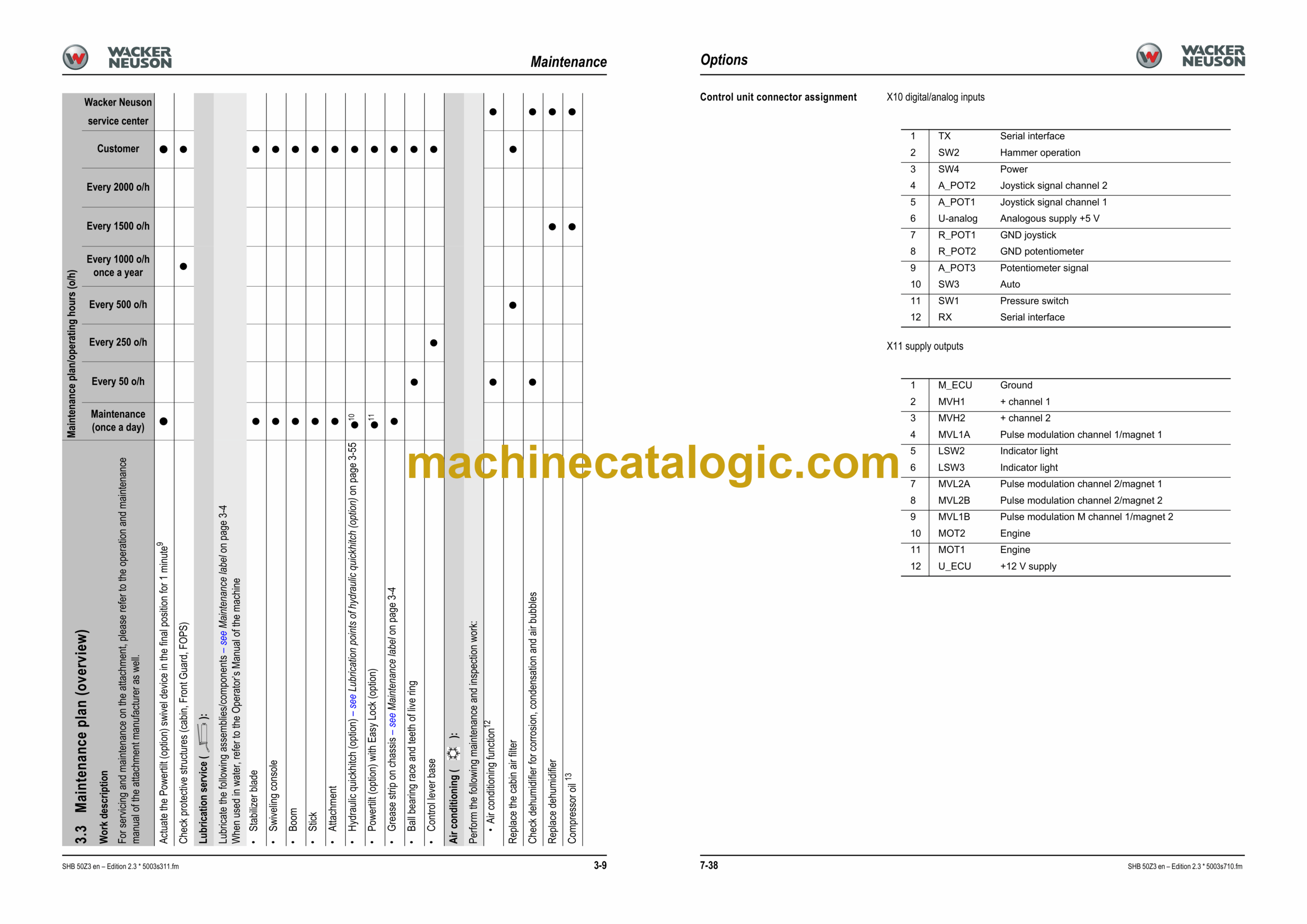
3.3 Maintenance plan (overview)
3.4 Introduction
3.5 Fuel system
3.6 Engine lubrication system
3.7 Cooling system
3.8 Air filter
3.9 V-belt
3.10 Pressure check
3.11 Test report
3.12 Hydraulic system
3.13 Traveling drive
3.14 Tracks
3.15 Overview of lubrication points
3.16 Electrical system
3.17 Battery
3.18 Cabin
3.19 General maintenance
4 Engine
4.1 Engine 4TNV88-PNS (up to serial no. AD07125)
4.2 Fuel system
4.3 Checking and adjusting valve clearance
4.4 Tightening order for cylinder head bolts
4.5 Checking the injection nozzles
4.6 Checking the nozzle jet
4.7 Injection time
4.8 Adjusting engine speed
4.9 Compression
4.10 Checking the coolant thermostat
4.11 Checking the thermal switch
4.12 Oil pressure switch
4.13 Checking the coolant circuit
4.14 Engine 4TNV88-PNS (from serial no. AH00579)
4.15 Fuel system
4.16 Removing the cylinder-head cover
4.17 Checking and adjusting valve clearance
4.18 Tightening order for cylinder head bolts
4.19 Checking the injection nozzles
4.20 Checking the nozzle jet
4.21 Injection time
4.22 Adjusting engine speed
4.23 Compression
4.24 Checking the coolant thermostat
4.25 Checking the thermal switch
4.26 Oil pressure switch
4.27 Checking the coolant circuit
4.28 Engine malfunctions
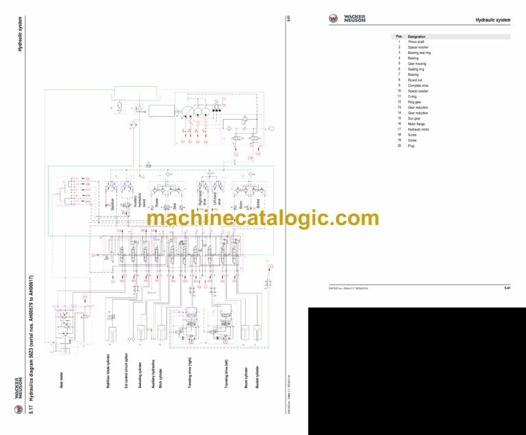
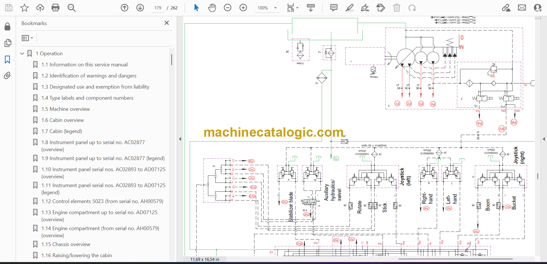
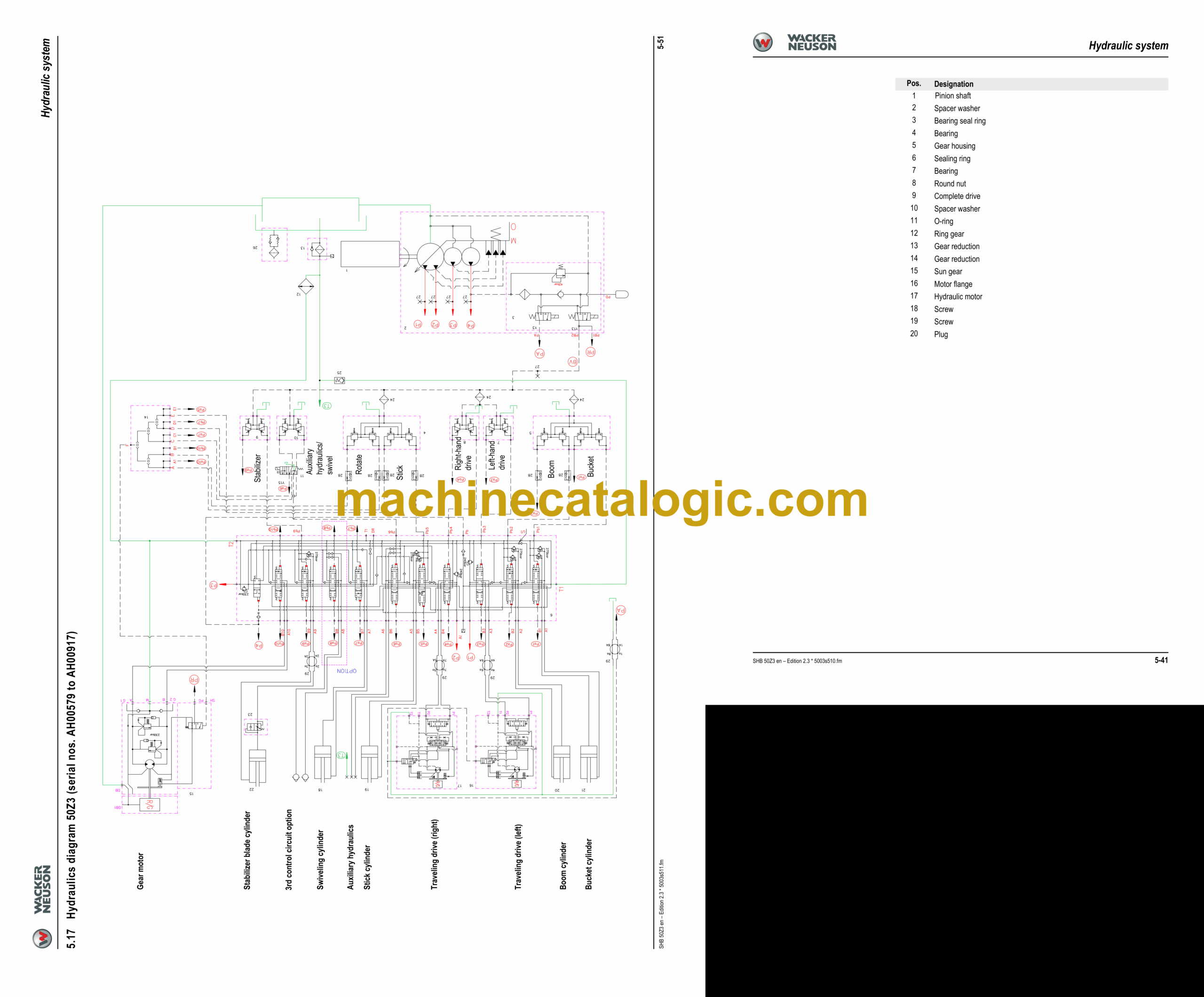
5 Hydraulic system
5.1 Hydraulic pump PVD-2B-44BP-16G5-4713F (up to AD07125) PVD-2B-41BP-16G5-4713F (from AH00579)
5.2 Main valve block
5.3 Drive counterbalancing system
5.4 Regeneration – stick section
5.5 Bucket pre-tension
5.6 Flow rate adjustment of auxiliary hydraulics
5.7 Pilot valves
5.8 Valves
5.9 Traveling drive
5.10 Swivel unit
5.11 Swivel joint
5.12 Breather filter
5.13 Malfunctions in the hydraulic system
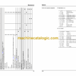
5.14 Hydraulics diagram (legend)
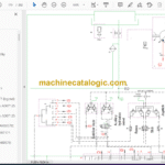
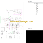
5.15 Hydraulics diagram 50Z3 (serial nos. AC02471 to AD07125)
5.16 Hydraulics diagram 50Z3 options (serial nos. AC02471 to AD07125)
5.17 Hydraulics diagram 50Z3 (serial nos. AH00579 to AH00917)
5.18 Hydraulics diagram 50Z3 options (serial nos. AH00579 to AH00917)
5.19 Hydraulics diagram 50Z3 (from serial no. AH00918)
5.20 Hydraulics diagram 50Z3 options (from serial no. AH00918)
5.21 Hydraulics diagram 50Z3 (from serial no. AJ03401)
5.22 Proportional controls diagram
5.23 Main valve block diagram 50Z3 A3
6 Electrical system
6.1 Ohm’s Law (current, voltage, resistance); power
6.2 Measuring equipment, measuring methods
6.3 Cable color coding
6.4 Relays
6.5 Electric units
6.6 Fuse box in instrument panel
6.7 Main fuse box with relays
6.8 Relays
6.9 Socket
6.10 Control lever push button
6.11 Instrument panel overview
6.12 Switches up to serial no. AD07125 (overview)
6.13 Switches from serial no. AH00579 (overview)
6.14 Alternator
6.15 Starter
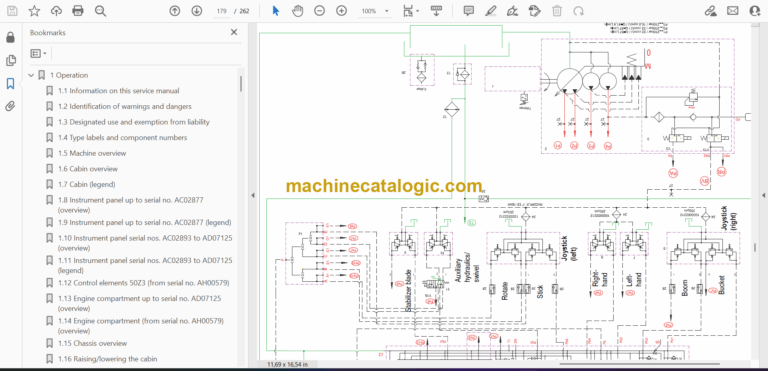
6.16 Wiring diagram legend (up to serial no. AC02889)
6.17 Wiring diagram (up to serial no. AC02889)
6.18 Wiring diagram legend (from serial no. AC02890)
6.19 Wiring diagram (from serial no. AC02890)
6.20 Engine/chassis wiring harness legend (up to serial no. AJ02831)
6.21 Engine/chassis wiring harness (up to serial no. AJ02831)
6.22 Engine/chassis wiring harness legend (from serial no. AJ02832)
6.23 Engine/chassis wiring harness (from serial no. AJ02832)
6.24 Switches wiring harness legend (up to serial no. AC02889)
6.25 Switches wiring harness (up to serial no. AC02889)
6.26 Switches wiring harness legend (from serial no. AC02890)
6.27 Switches wiring harness (from serial no. AC02890)
6.28 Cabin roof wiring harness
6.29 Armrest wiring harness
6.30 Boom working light wiring harness
6.31 Rotating beacon wiring harness
7 Options
7.1 Air conditioning
7.2 Air-suspension seat
7.3 Counterweight
7.4 Long stick
7.5 Control circuit (pipework) connections for grab
7.6 3rd control circuit connections
7.7 Auxiliary hydraulics connections
7.8 Fuel-filling pump
7.9 Central lubrication system
7.10 Service valve
7.11 Safe load indicator D (safety valve for boom)
7.12 Safe load indicator F (safety valves for boom and stick)
7.13 3rd control circuit
7.14 Electric auxiliary hydraulics
7.15 Auxiliary hydraulics shock cartridge
7.16 3rd control circuit shock cartridge
7.17 Drive interlock (antitheft protection)
7.18 Quickhitch
7.19 Automatic idling speed feature
7.20 Proportional controls
7.21 Automatic engine speed setting (Tier 3A from AH00579)
7.22 Telematic


