Format: PDF (Printable Document)
File Language: English
File Pages: 156
File Size: 30.24 MB (Speed Download Link)
Brand: Wacker Neuson
Model: G25, G35, G50 Mobile Generator
Type of Document: Service and Repair Manual
$ 45
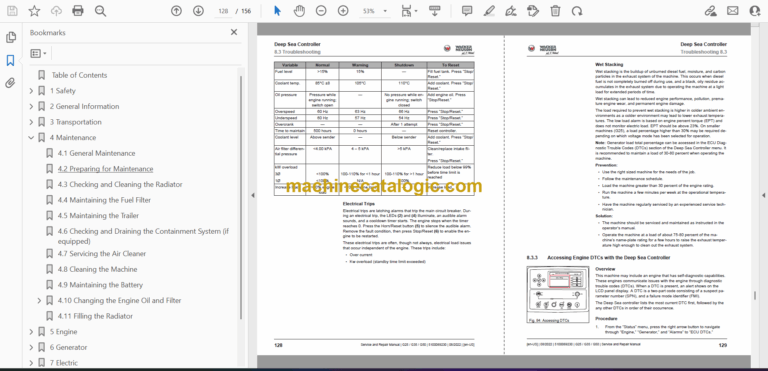
Table of Contents
1 Safety
1.1 Signal Words Used in This Manual
1.2 Safety Guidelines for Operating the Machine
1.3 Safety Instructions for Parking
1.4 Safety Guidelines for Lifting and Transporting
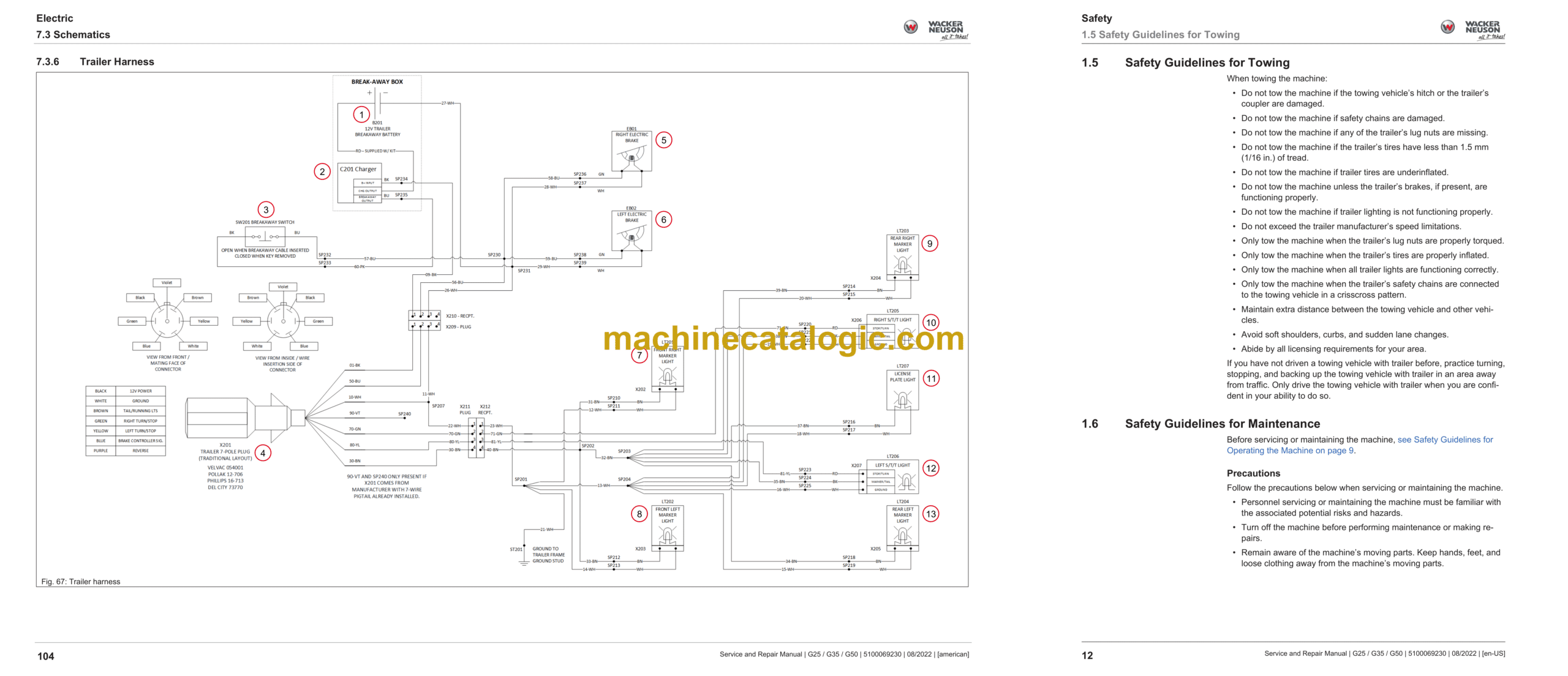
1.5 Safety Guidelines for Towing
1.6 Safety Guidelines for Maintenance
1.7 Safety Instructions for Handling Oils and Greases
1.8 Safety Instructions for Working on the Electrical System
2 General Information
2.1 Standard Torque Values
3 Transportation
3.1 Lifting the Machine
3.2 Towing the Machine
3.3 Preparing the Machine for Transport
3.4 Testing the Breakaway System—Electric Brakes
3.5 Testing the Breakaway System—Hydraulic Surge Brakes
4 Maintenance
4.1 General Maintenance
4.2 Preparing for Maintenance
4.3 Checking and Cleaning the Radiator
4.4 Maintaining the Fuel Filter
4.5 Maintaining the Trailer
4.6 Checking and Draining the Containment System (if equipped)
4.7 Servicing the Air Cleaner
4.8 Cleaning the Machine
4.9 Maintaining the Battery
4.10 Changing the Engine Oil and Filter
4.10.1 Changing the Engine Oil Filter
4.11 Filling the Radiator
5 Engine
5.1 Component Locations—Kohler
5.2 Type Label Engine Number
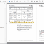
5.3 Technical Data
5.3.1 Engine
5.3.2 Engine Oil Viscosity
5.3.3 Coolant
5.4 Troubleshooting
5.4.1 Start System
5.5 Repair
5.5.1 Removing and Installing the Engine—Kohler
6 Generator
6.1 Component Locations—Kohler
6.2 Technical Data
6.2.1 Machine
6.2.2 Generator
6.3 Troubleshooting
6.3.1 Output Voltage
6.4 Repair
6.4.1 Removing and Installing the Main Circuit Breaker
6.4.2 Removing and Installing the Generator
6.4.3 Removing and Installing the Voltage Selector Switch (VSS)
6.4.4 Removing and Installing the Emergency Stop Switch
6.4.5 Removing and Installing the Voltage Adjusting Rheostat
6.4.6 Removing and Installing the Automatic Voltage Regulator (AVR)
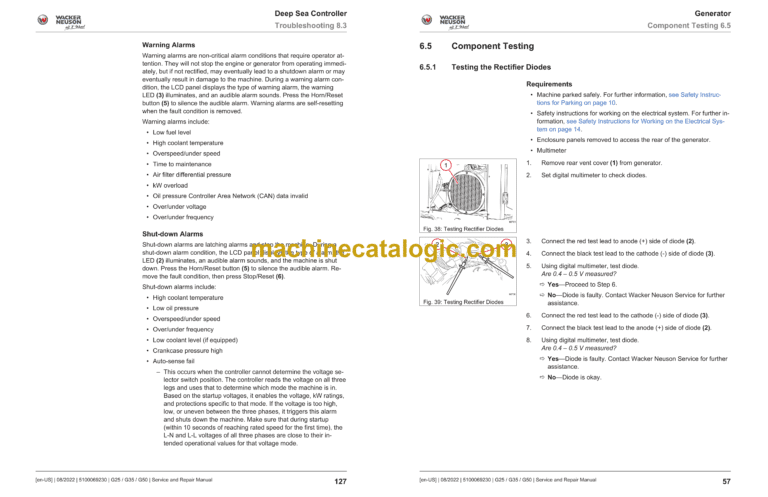
6.5 Component Testing
6.5.1 Testing the Rectifier Diodes
6.5.2 Testing the Emergency Stop Switch
6.5.3 Testing the Main Circuit Breaker
6.5.4 Testing the Lug Door Switch
6.5.5 Testing the Auxiliary Winding
6.5.6 Testing the Stator Windings
6.5.7 Testing the Stator Windings (at Generator)
6.5.8 Testing the Main Rotor Windings
6.5.9 Testing the Exciter Windings
6.5.10 Testing the Rheostat Voltage
6.5.11 Testing the Exciter Stator
6.5.12 Testing the Excitation System (Flashing)
6.5.13 Testing the Automatic Voltage Regulator (AVR)
7 Electric
7.1 Electrical Component Locations
7.2 Theory of Operation
7.2.1 Controls Circuit —Theory of Operation
7.2.2 Generator Circuit —Theory of Operation
7.2.3 Terminal Lugs & Receptacles —Theory of Operation
7.2.4 Current Transformers —Theory of Operation
7.2.5 Phase Switch —Theory of Operation
7.2.6 Main Stator —Theory of Operation
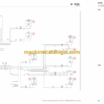
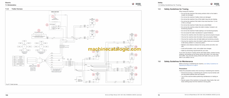
7.3 Schematics
7.3.1 Electrical Component Symbols/How to Read a Schematic
7.3.2 AC Schematic—480V
7.3.3 AC Schematic—600V
7.3.4 DC Schematic (1 of 2)
7.3.5 DC Schematic (2 of 2)
7.3.6 Trailer Harness
7.4 Repair
7.4.1 Removing and Installing the 150A Circuit Breaker
7.4.2 Removing and Installing the Starter Motor and Solenoid
7.4.3 Removing and Installing the Fuel Lift Pump
7.4.4 Removing and Installing the Coolant Level Sensor
7.5 Component Testing
7.5.1 Testing/Repairing Electrical System and Components
7.5.2 Testing the 150A Circuit Breaker
7.5.3 Testing the Starter Solenoid
7.5.4 Testing the Fuel Lift Pump
7.5.5 Testing the Coolant Level Sensor
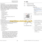
8 Deep Sea Controller
8.1 Deep Sea Controller Buttons / Functions
8.2 General Operation
8.2.1 Mobile Generator Controller Power Switch
8.2.2 Working with Deep Sea Controller
8.2.3 Emergency Stop Switch
8.2.4 Engine and Generator Monitoring
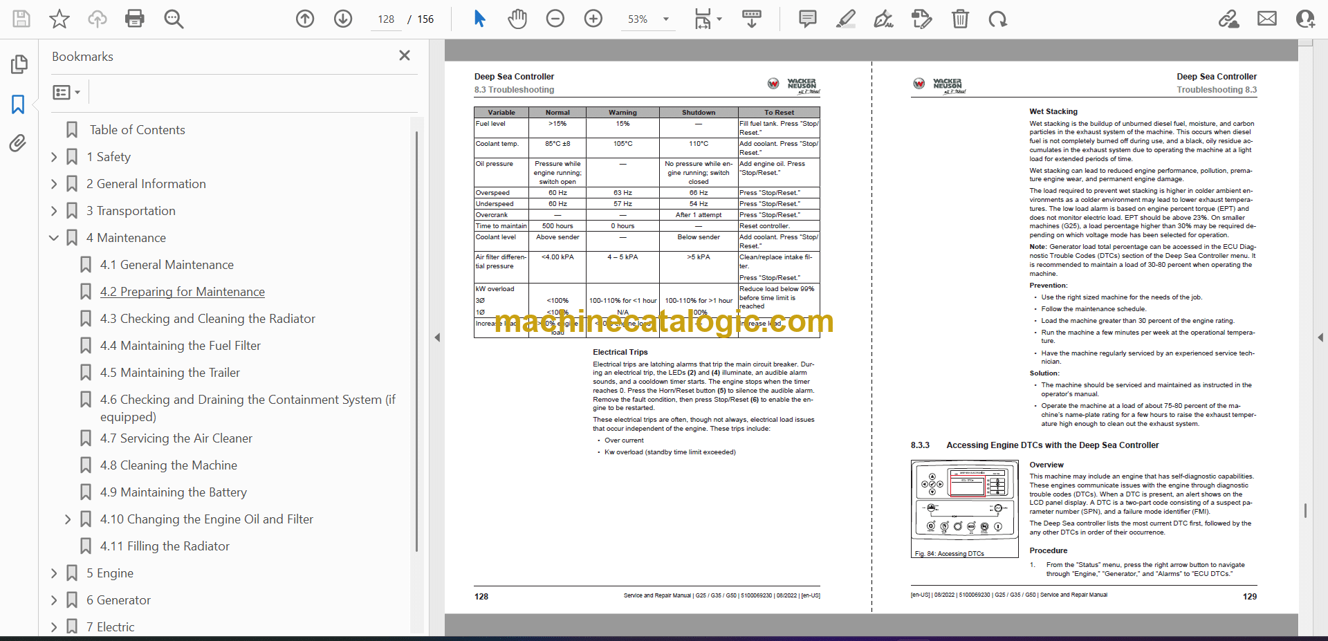
8.3 Troubleshooting
8.3.1 Deep Sea Controller
8.3.2 Alarms and Shut-down
8.3.3 Accessing Engine DTCs with the Deep Sea Controller
8.3.4 General Fault Mode Indicator (FMI) Chart
8.3.5 List of Engine Diagnostic Trouble Codes
8.3.6 List of Deep Sea Controller Diagnostic Trouble Codes
8.4 Repair
8.4.1 Removing and Installing the Fuel Sending Unit
8.4.2 Removing and Installing the Main Power Switch
8.4.3 Removing and Installing the Deep Sea Controller
8.5 Component Testing
8.5.1 Testing the Fuel Sending Unit
8.5.2 Testing the Main Power Switch
8.5.3 Testing the Deep Sea Controller
9 Vehicle Frame
9.1 Component Locations
9.2 Technical Data
9.2.1 Dimensions
9.2.2 Trailer and Skid
9.3 Repair
9.3.1 Removing and Installing the Roof, Panels & Doors
9.3.2 Removing and Installing the Battery Charger
9.3.3 Removing and Installing the Control Box
9.4 Component Testing
9.4.1 Testing the Breakaway Box
