Format: PDF (Printable Document)
File Language: English
File Pages: 94
File Size: 3.46 MB (Speed Download Link)
Brand: Wacker Neuson
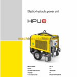
Model: HPU8 Electri-hydraulic Power Unit
Type of Document: Service Manual
$ 45
1 Operation
1.1 Notices on this service manual
1.2 Identification of warnings and dangers
1.3 Explanation of symbols and abbreviations
Explanation of symbols
Abbreviations
Conversion table
1.4 Warranty and liability
Exemption from warranty and liability
1.5 Labels
Type labels
1.6 Overall view (7.5 kW version)
1.7 Overall view (9 kW version)
1.8 Outside view of control box
1.9 Overview of components
1.10 Indicator lights and warning lights (overview)
Indicator lights
Hour meter
2 Technical data
2.1 Models and trade names
2.2 Electric motor
2.3 Tires
2.4 Hydraulic system
Hydraulic hose specifications
2.5 Noise emissions
2.6 Vibration
2.7 Weight
Weight of power unit
2.8 Tightening torques
Model-specific tightening torques
General tightening torques
Tightening torques for high-resistance threaded fittings
2.9 Dimensions
3 Maintenance
3.1 Information on maintenance
Responsibilities and prerequisites
Important safety instructions on maintenance
3.2 Fluids and lubricants
Hydraulic oil types (depending on temperature)
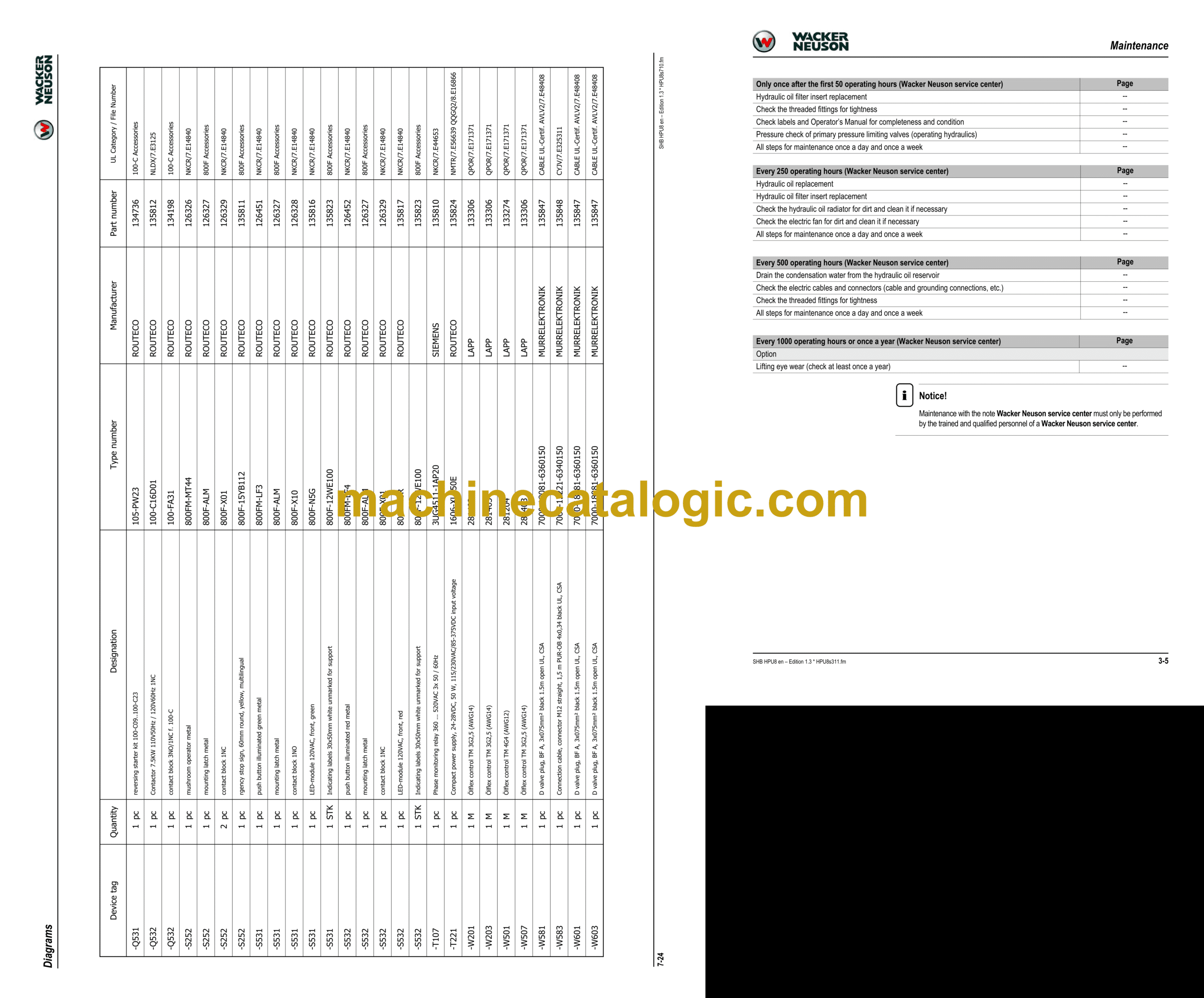
3.3 Maintenance plan
3.4 Cooling system
Important information regarding the cooling system
Cleaning the radiator
3.5 Hydraulic system
Important information on the hydraulic system
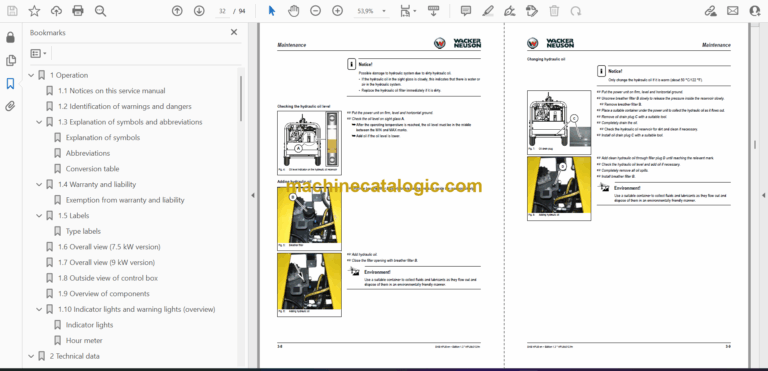
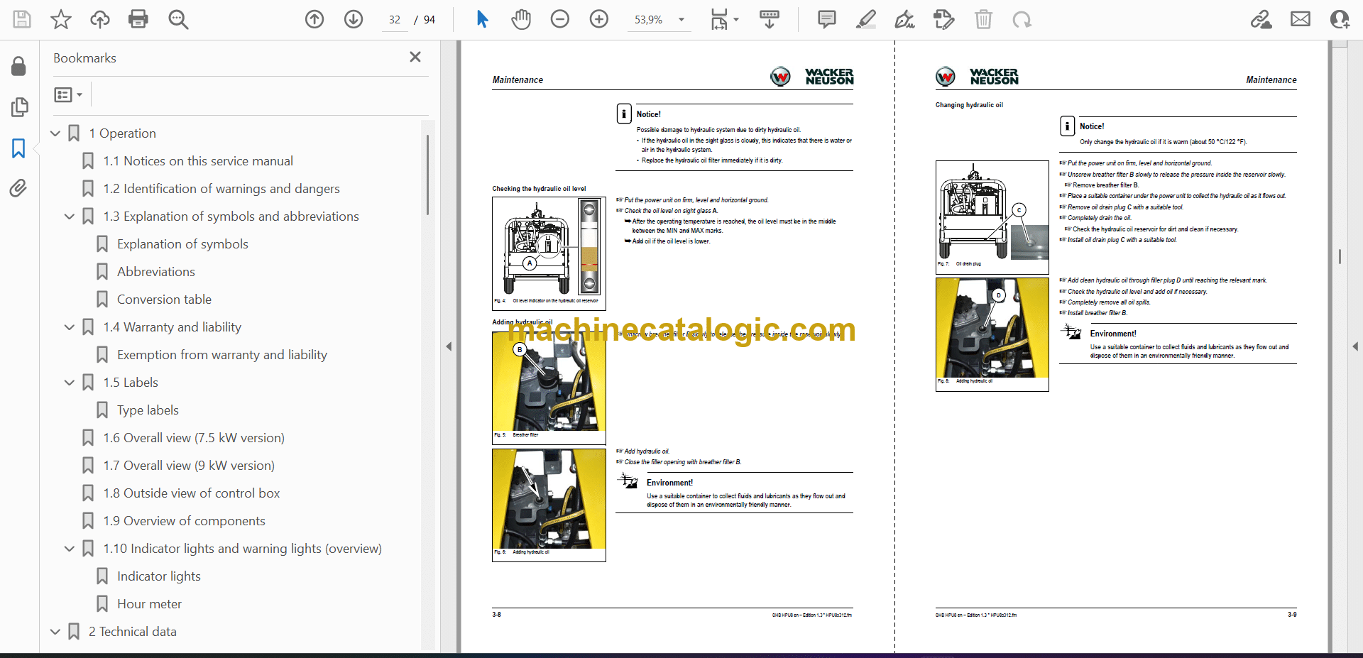
Checking the hydraulic oil level
Adding hydraulic oil
Changing hydraulic oil
Replacing the hydraulic oil filter
Draining condensation water from the hydraulic oil reservoir
Checking the hydraulic system for leaks and general condition
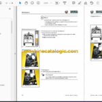
3.6 Maintenance of attachments
Important information regarding maintenance of attachments
3.7 Electrical system
Important information regarding the electrical system
Checking the indicator lights
3.8 Tires
Inspection work
Tire/wheel replacement
3.9 Maintenance of the lifting point
3.10 Cleaning and maintenance
Important information on cleaning and maintenance
Use of solvents
Cleaning the power unit
3.11 Putting out of operation/back into operation
Putting out of operation temporarily
Putting back into operation
3.12 Permanently putting out of operation
Disposal
4 Engine
4.1 Overview
5 Hydraulic system
5.1 How it works
5.2 Overview of components
Hydraulic reservoir components
5.3 Breather filter (hydraulic oil reservoir)
5.4 Troubleshooting the hydraulic system
6 Electrical system
Important information regarding the electrical system
6.1 Ohm’s Law (current, voltage, resistance); power
6.2 Measuring equipment, measuring methods
6.3 Overview of components
6.4 Switch box with protective switching device ABB
6.5 Switch box with protective switching device Pilz
6.6 Control box (option 9kW)
6.7 Control box malfunctions
Malfunction indicator light illuminates
Malfunction indicator light does not illuminate
7 Diagrams
7.1 Hydraulics diagram (7,5 kW and Option 9 kW)
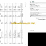
7.2 Wiring diagram legend (applies to protective switching device ABB and Pilz)
7.3 Wiring diagram part 1 (applies to protective switching device ABB and Pilz)
7.4 Wiring diagram part 2 (applies to protective switching device ABB and Pilz)
7.5 Wiring diagram part 3 (applies to protective switching device ABB)
7.6 Wiring diagram part 3 (applies to protective switching device Pilz)
7.7 Panel overview (Option 9 kW)
7.8 Panel layout (Option 9 kW)
7.9 Cable overview (Option 9 kW)
7.10 Power supply (Option 9 kW)
7.11 Control voltage 115VAC (Option 9 kW)
7.12 Control voltage 24VDC CLASS2 (Option 9 kW)
7.13 Emergency stop (Option 9 kW)
7.14 Hydraulic pump (Option 9 kW)
7.15 Hydraulic pump (Option 9 kW)
7.16 Hydraulic pump shutdown (Option 9 kW)
7.17 Solenoid valve load relieving (Option 9 kW)
7.18 Oil cooling fan (Option 9 kW)
7.19 Terminal diagram (Option 9 kW)
7.20 Terminal diagram (Option 9 kW)
7.21 Cable overview (Option 9 kW)
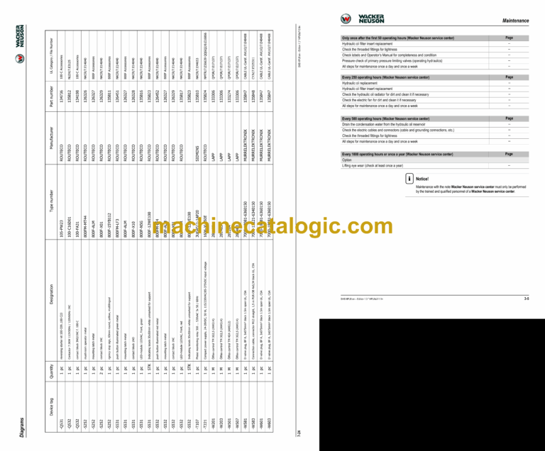
7.22 Parts list (Option 9 kW)
8 Special tools PAL
