Format: PDF (Printable Document)
File Language: English
File Pages: 705
File Size: 73.50 MB (Speed Download Link)
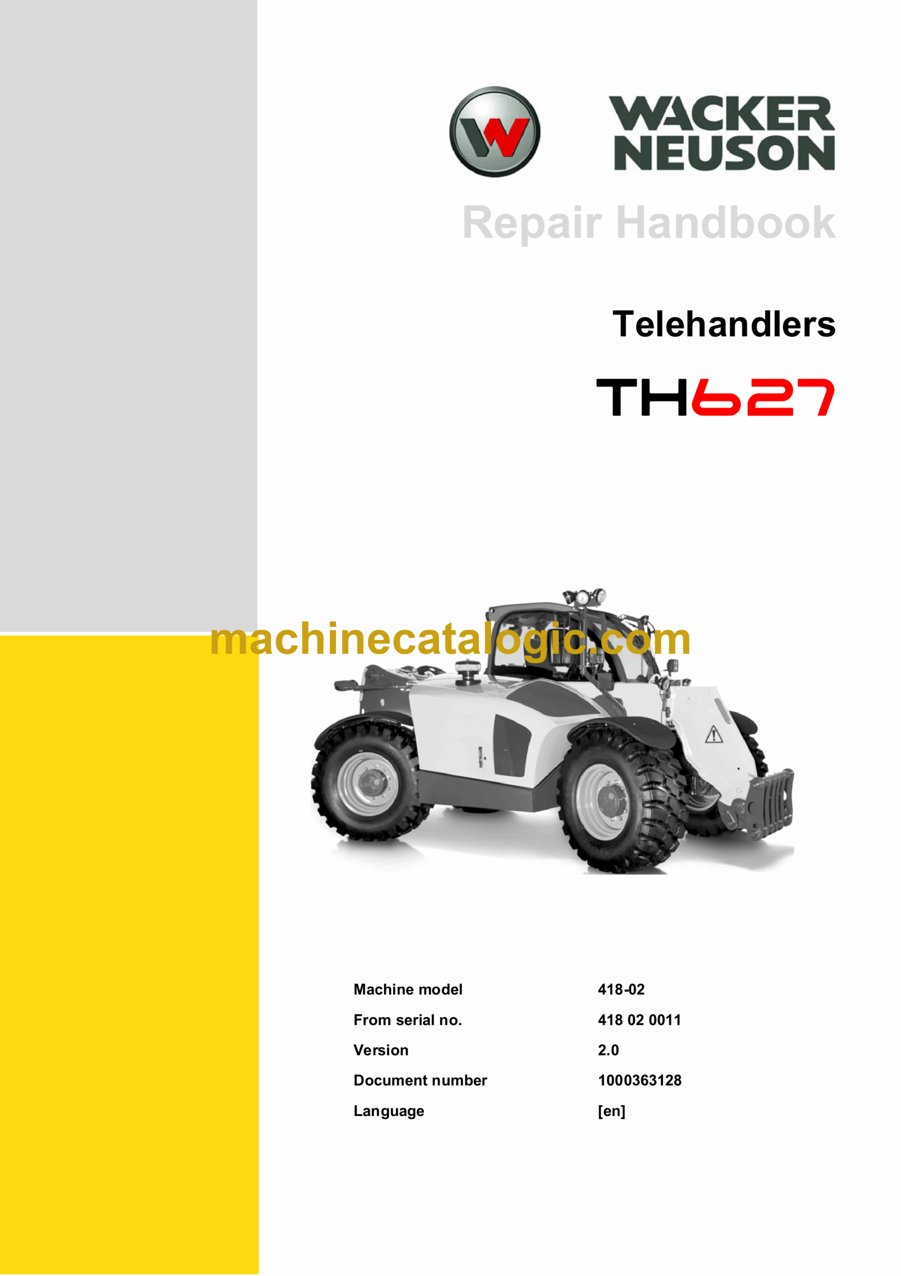
Brand: Wacker Neuson
Model: TH627 Telehandlers
Type of Document: Repair Handbook
$ 45
Repair Handbook
E Introduction
E.1 Notes on the repair manual
E.2 Safety instructions
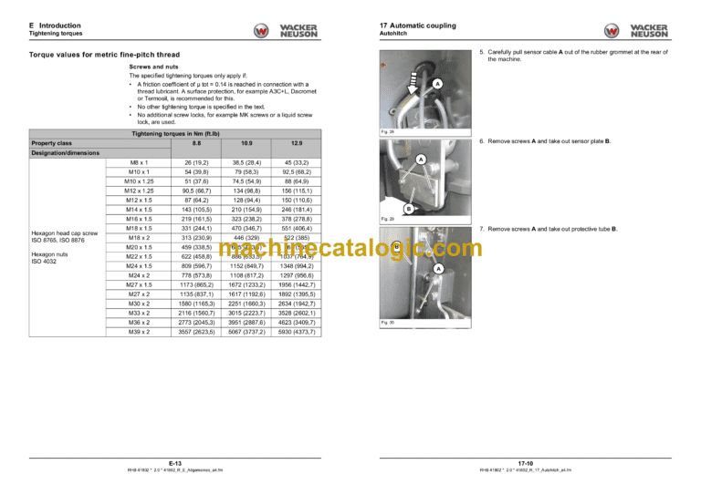
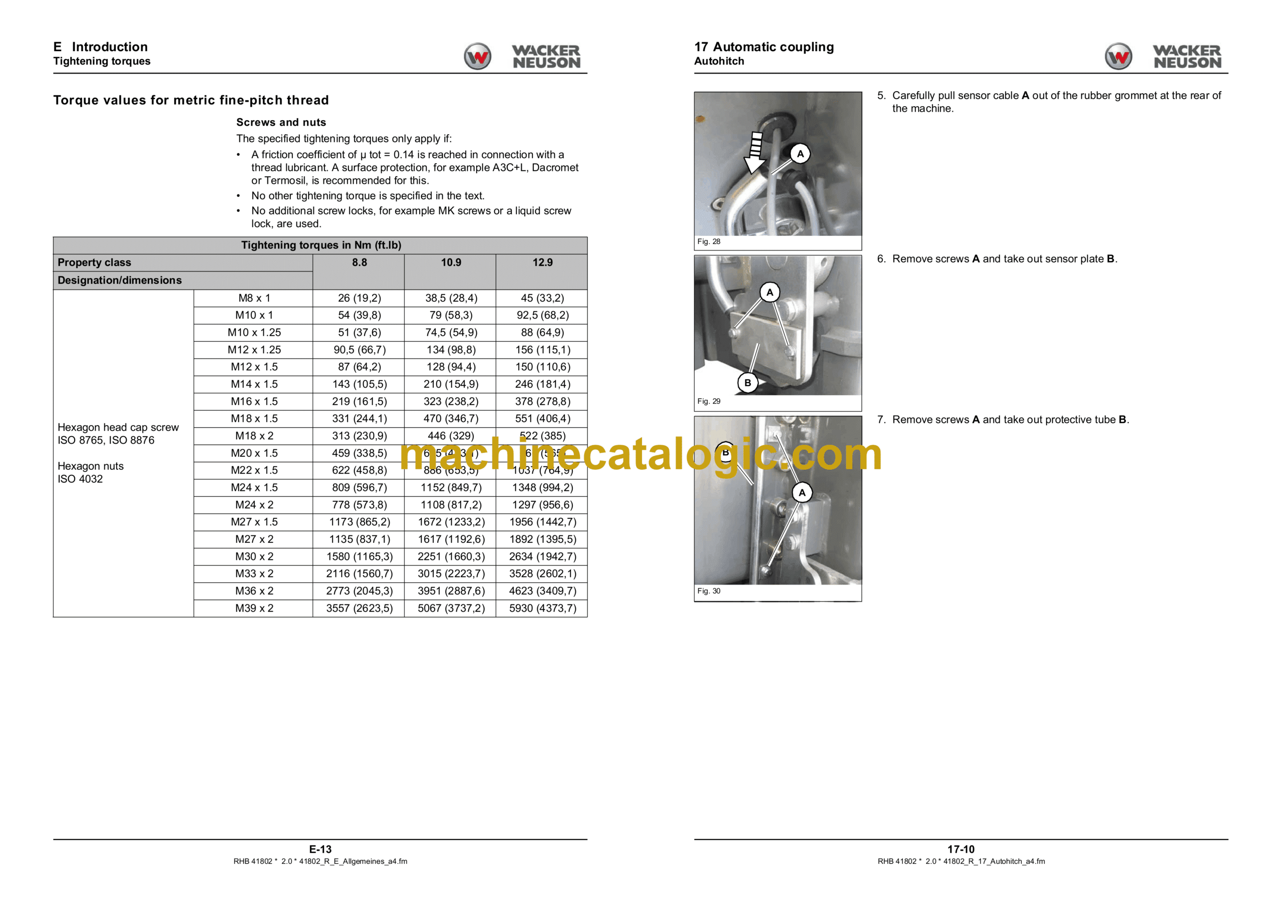
E.3 Tightening torques
1 Maintenance
1.1 Maintenance preparations, instructions
1.2 Maintenance overview
1.3 Fluids and lubricants
1.4 Maintenance accesses
1.5 Cleaning and maintenance work
1.6 Lubrication work
1.7 Fuel system
1.8 Engine lube oil system
1.9 Exhaust gas cleaning
1.10 Cooling system
1.11 Air filter
1.12 V-belt/toothed belt
1.13 Hydraulic system
1.14 Electrical system
1.15 Heating, ventilation, air conditioning
1.16 Washer system
1.17 Axles/traveling drive
1.18 Brake system
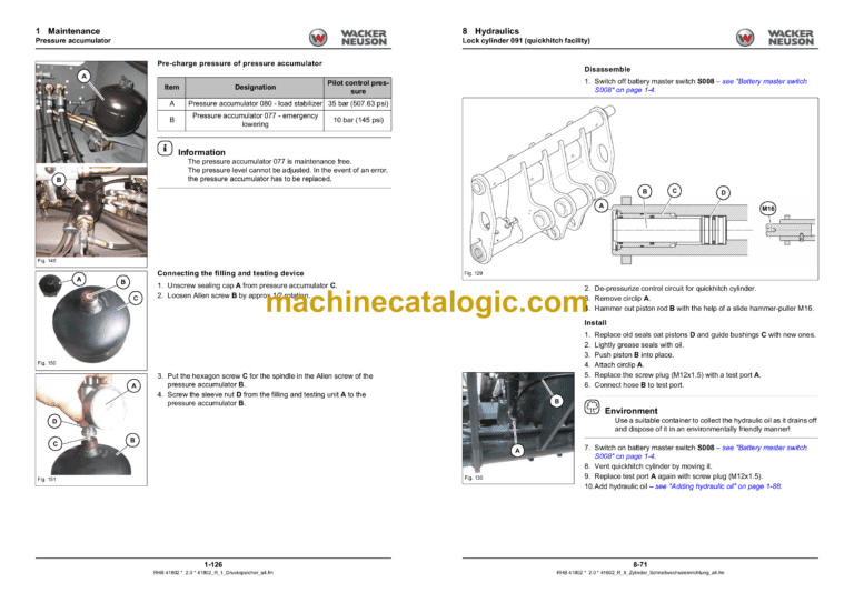
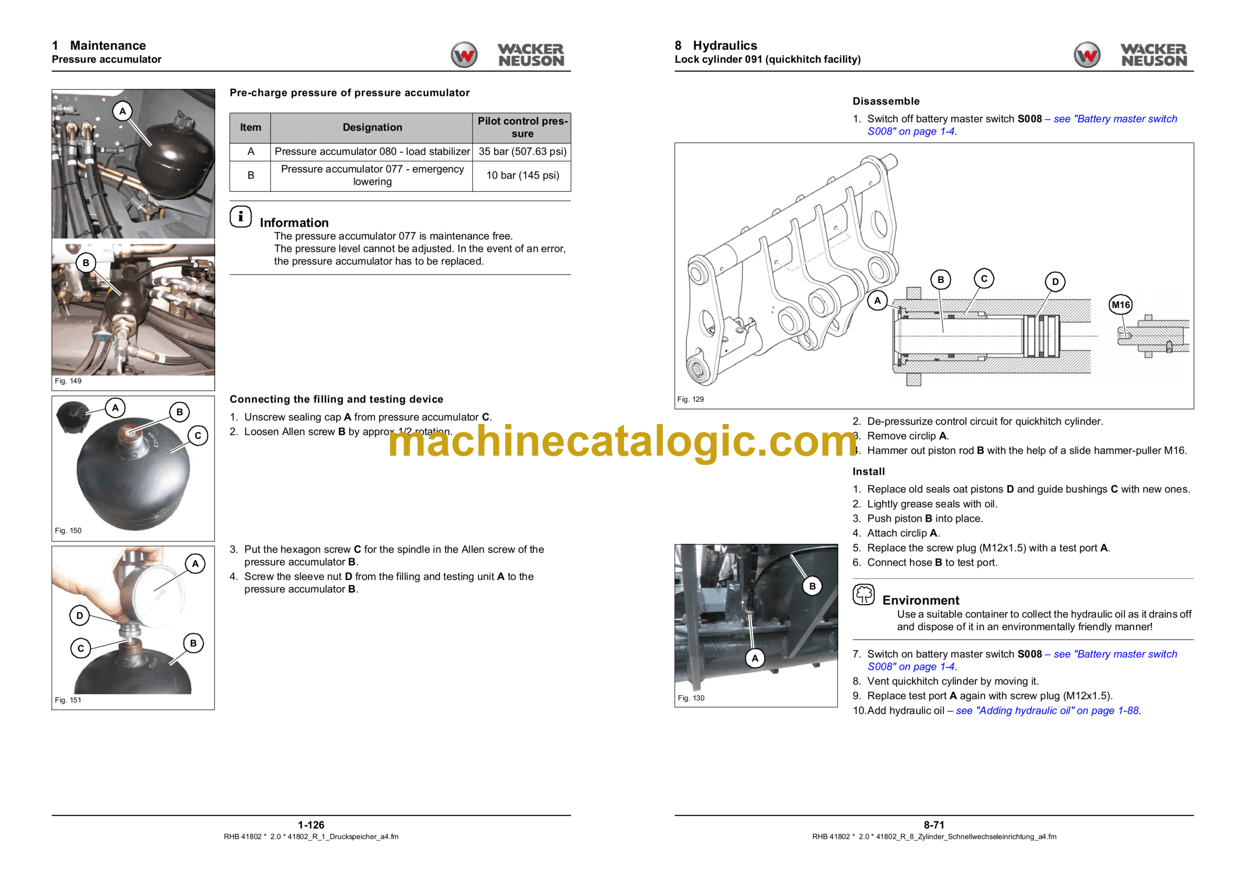
1.19 Pressure accumulator
1.20 Tyres
1.21 Attachments
1.22 Trailer coupling
1.23 Camera system
1.24 Machine preservation
2 Engine
2.1 Kohler KDI 2504 TCR motor
2.2 Engine suspension
2.3 Starter M001
2.4 Generator G001
2.5 Centaflex-coupling
2.6 Fuel tank
2.7 Tank sensor B001
2.8 Air filter
2.9 Accelerator pedal R011
3 Cooling
3.1 Combined radiator
3.2 Fan wheel/fan mounting
3.3 Hydraulic motor fan
3.4 Fan pump/pump mounting
4 Traction drive/gears/ drive shafts
4.1 Variable displacement pump VII
4.2 Variable displacement motor VIII
4.3 Cardan shaft
5 Axles
5.1 Type label and overview
5.2 Drain, fill and check plugs
5.3 Screw connections and tightening torques
5.4 Special tools
5.5 Track setting
5.6 Front axle
5.7 Rear axle
5.8 Front/rear axle planetary drive
5.9 Front axle/rear axle
6 Brakes
6.1 Brake pedal
6.2 Replacing brake linings
6.3 Brake caliper
6.4 Brake disk
6.5 Main brake cylinder 030
6.6 Parking brake
7 Steering
7.1 Steering orbitrol IV
7.2 Steering mode valve XXVI
7.3 Steering cylinder 018/019
7.4 Steering column
8 Hydraulics
8.1 Control unit XIII
8.2 Hydraulic oil tank XX
8.3 Working hydraulics Gear pump I
8.4 Pressure accumulator 077
8.5 Pressure accumulator 080
8.6 Hose burst valve with load stabiliser XIV
8.7 Hose burst valve for push-out ram 089
8.8 Tilt cylinder hose burst valve 087
8.9 Lifting cylinder 085
8.10 Boom cylinder 089
8.11 Tilt ram 087
8.12 Compensation cylinder 086
8.13 Lock cylinder 091 (quickhitch facility)
8.14 Telescopic boom
8.15 Tilt rod and rocker arm
8.16 Quickhitch
8.17 Telescopic boom hose pipes
9 Electrical system
9.1 Main fuse box N025
9.2 Control lever D002
9.3 Instrument panel
9.4 Inch potentiometer R002
9.5 Rotary angle encoder Lifting arm R023
9.6 Travel sensor for bucket repositioning B028
9.7 Creep gear potentiometer R003
9.8 Hand throttle potentiometer R012
9.9 Load sensor B008
9.10 Safe load indicator P006
9.11 Controller
12 Trim
12.1 Engine cover
12.2 V-belt cover
12.3 Transmission tunnel cover
12.4 Underride protection
12.5 Cab front covering
12.6 Cladding in the cabins
14 Cab
14.1 Operator seat
14.2 Cabin
14.3 Cabin bearing
15 Heating/air conditioning
15.1 Heater/air conditioning system
15.2 Air conditioning system compressor Y031
15.3 Air conditioning cooler (capacitor)
15.4 Dehumidifier
17 Automatic coupling
17.1 Autohitch
17.2 Height-adjustable trailer coupling
17.3 Automatic/rotating trailer coupling
17.4 Tow coupling
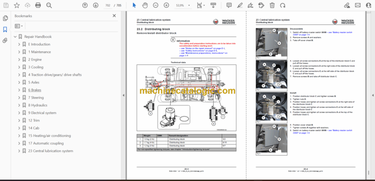
23 Central lubrication system
23.1 Central lubrication unit M016
23.2 Distributing block
