Format: PDF (Printable Document)
File Language: English
File Pages: 300
File Size: 62.28 MB (Speed Download Link)
Brand: Wacker Neuson
Model: WL28 Wheel Loader
Type of Document: Service Manual
$ 45
Contents
E Introduction
E.1 Notice on this service manual
E.2 Technical data
E.3 Tightening torques
E.4 Safety instructions
E.5 Special tools
B Operation
B.1 Overview of control elements
B.2 Indicator lights and warning lights (overview)
1 Maintenance
1.1 Information on maintenance
1.2 Maintenance overview
1.3 Lubrication plan
1.4 Fluids and lubricants
1.5 Maintenance accesses
1.6 Cleaning and maintenance
1.7 Lubrication work
1.8 Fuel system
1.9 Engine lubrication system
1.10 Cooling system
1.11 Air filter
1.12 V-belt/toothed belt
1.13 Hydraulic system
1.14 Electrical system
1.15 Heating and ventilation
1.16 Washer system
1.17 Axles/travel drive
1.18 Braking system
1.19 Tires
1.20 Maintenance and servicing work on attachments
1.21 Maintenance of options
2 Engine
2.1 Perkins engine 404D-22 (35.7 kW)
2.2 Alternator
2.3 Starter
3 Cooling
3.1 Removing/installing the radiator
3.2 Removing/installing fan blades
4 Travel drive
4.1 Traveling drive hose routing
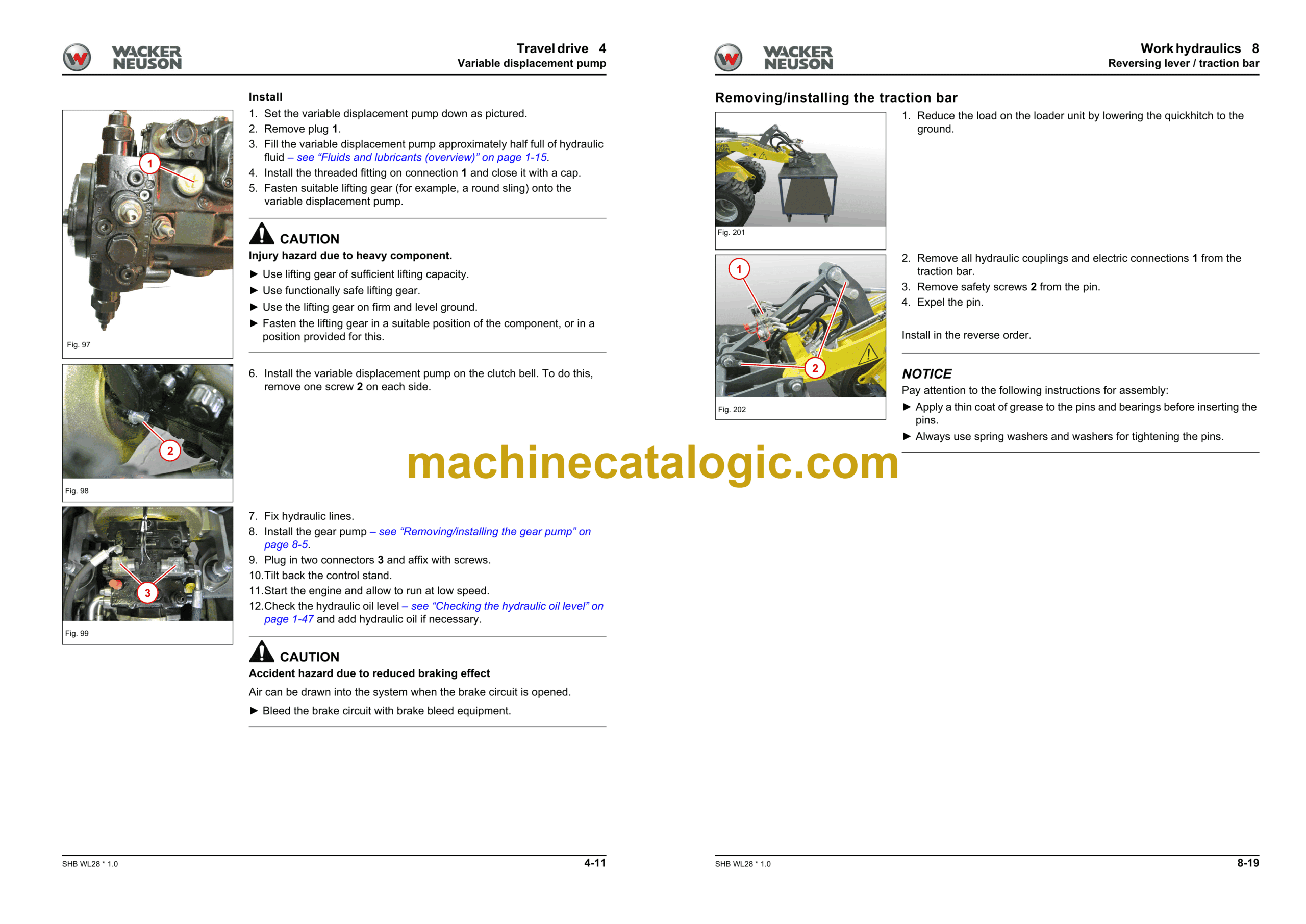
4.2 Variable displacement pump
4.3 Variable displacement motor M20
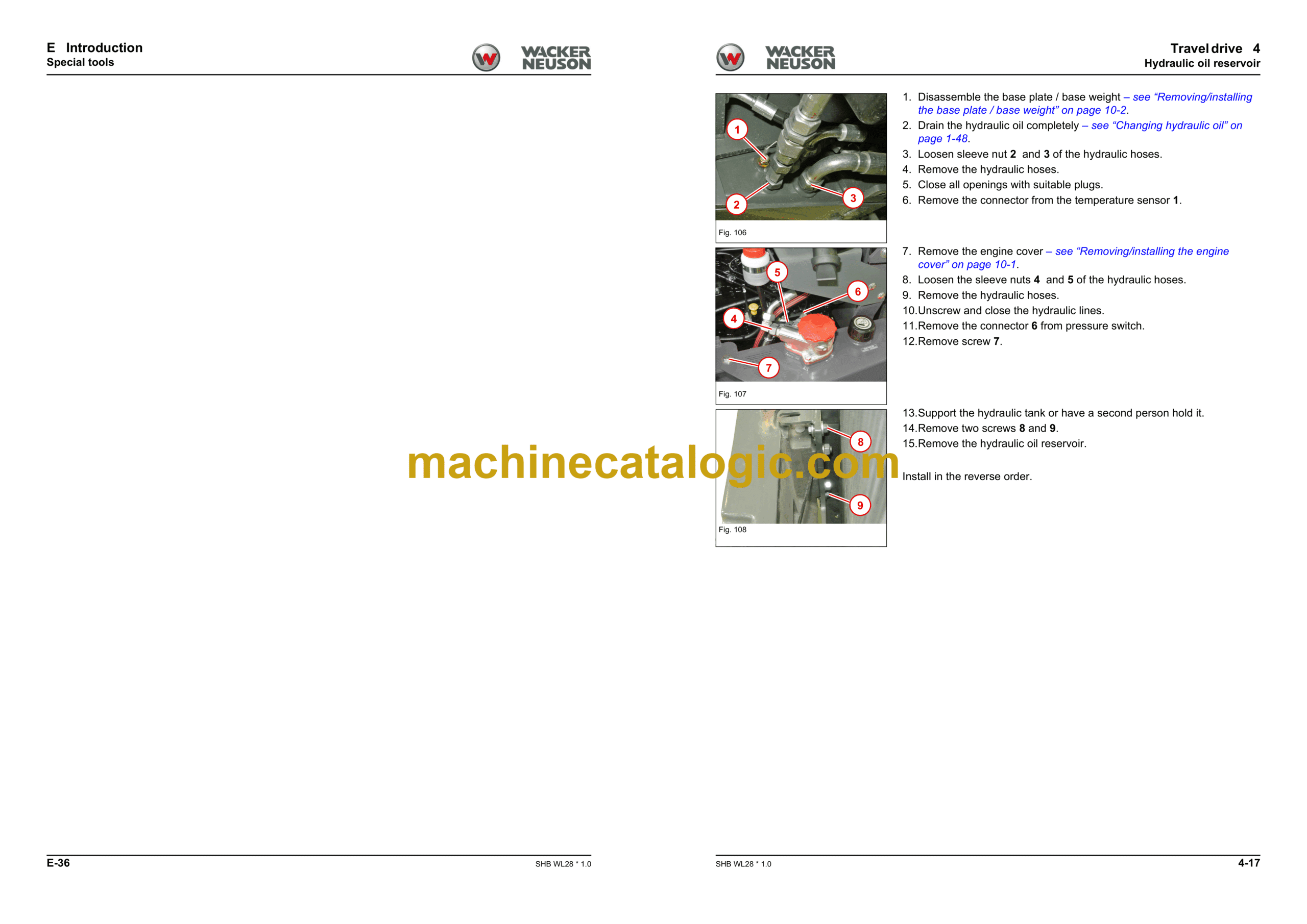
4.4 Hydraulic oil reservoir
4.5 Removing/installing the cardan shaft
4.6 Removing/installing check valve V72
4.7 Troubleshooting
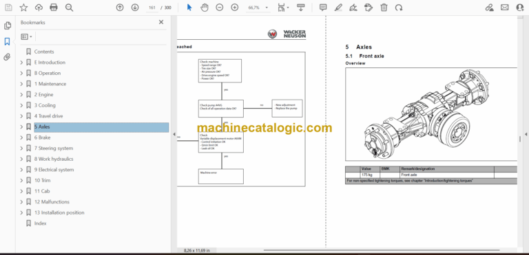
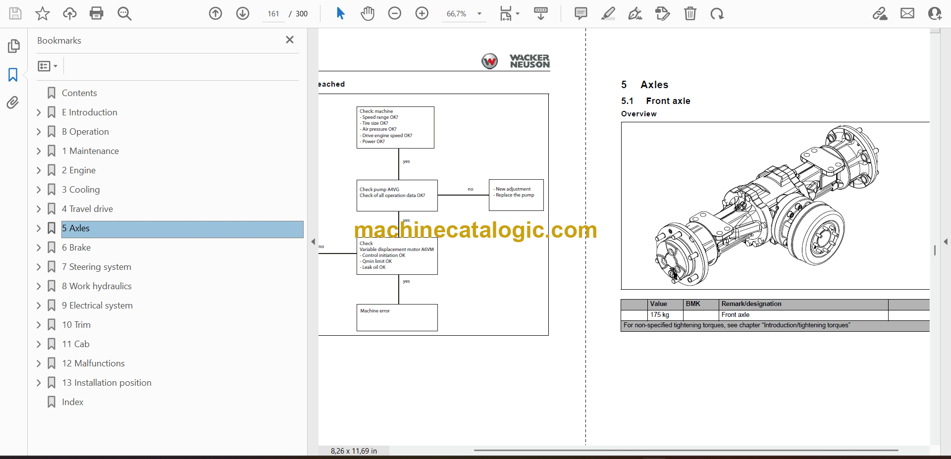
5 Axles
5.1 Front axle
5.2 Rear axle
5.3 Type label – front/rear axle
6 Brake
6.1 Brake system overview
6.2 Removing/installing the brake pedal
6.3 Removing/installing the parking brake
6.4 Removing/installing the parking brake Bowden cable
6.5 Master brake cylinder
7 Steering system
7.1 Steering orbitrol S4
7.2 Removing/installing the steering wheel
7.3 Removing/installing the steering column
7.4 Removing/installing the steering column gas strut
7.5 Removing/installing steering cylinder A21
7.6 Checking the steering hydraulics
8 Work hydraulics
8.1 Overview
8.2 Hose routing lift and tilt rams
8.3 Gear pump P37
8.4 Removing/installing lock cylinder A4
8.5 Removing/installing the lock pin
8.6 Removing/installing the tilt cylinder
8.7 Removing/installing the loader unit
8.8 Removing/installing the lift cylinder
8.9 Removing/installing the reversing lever / traction bar
8.10 Removing/installing solenoid valve V30
8.11 Removing/installing the quickhitch
8.12 Removing/installing the control valve
8.13 Designation of hydraulic components
8.14 Hydraulic diagram – HDM19/4
8.15 Hydraulics diagram – HDM19/3 with HDS15/1
8.16 Hydraulic diagram – HDM19/3
8.17 Hydraulics diagram – HDM19/3 with SD11/1
8.18 Hydraulic diagram – HDM19/4 with rear hydraulics
8.19 Hydraulics diagram – HDM19/3 with SD11/1
9 Electrical system
9.1 Overview
9.2 Fuses
9.3 Joystick
9.4 Removing/installing the battery master switch
9.5 Electrical diagram – power supply engine (FG01-01)
9.6 Electrical diagram – Instrument (FG02-01)
9.7 Electric diagram – Traveling drive, A6VM, parking brake (FG03-02)
9.8 Electrical diagram – Tool locking, horn (FG04-01)
9.9 Electric diagram – Lighting, cab and protective roof (FG05-01)
9.10 Electric diagram – Lighting, protective roof eps (FG05-02)
9.11 Electric diagram – Lighting 1 StVZO (FG06-01)
9.12 Electric diagram – Lighting 2 StVZO (FG06-02)
9.13 Electrical diagram – Turn indicator/horn (FG06-03)
9.14 Electric diagram – Electric connection 12V (FG07-01)
9.15 Electric diagram – 3-pole electric connection comfort (FG07-02)
9.16 Electric diagram – Window wiper for protective roof LK182 (FG08-02)
9.17 Electric diagram – Hydraulic control circuits, differential lock (FG09-01)
9.18 Electrical diagram – Electric lock block (FG10-01)
9.19 Electrical diagram – Loader unit stabilizer (FG11-01)
9.20 Electrical diagram – Operator’s seat comfort (FG12-01)
9.21 Electrical diagram – Telematics module (FG13-01)
9.22 Electric diagram – Cab 1 – Heater (FG15-01)
9.23 Electric diagram – Cab 2 – Window wiper (FG15-02)
9.24 Electric diagram – Cab 3 – Radio (FG15-03)
9.25 Designation of electrical components
10 Trim
10.1 Removing/installing the engine cover
10.2 Removing/installing the base plate / base weight
10.3 Installing / removing rear weight
11 Cab
11.1 Removing/installing the operator seat
11.2 Removing/installing the indicating instrument
11.3 Removing/installing the starter
11.4 Removing/installing the 12 V connector
11.5 Removing/installing the control lever console
11.6 Radio
11.7 Removing/installing the armrest
11.8 Removing/installing the heating
11.9 Removing/installing the cabin
11.10 Removing/installing the base plate
12 Malfunctions
12.1 Towing a machine
13 Installation position
13.1 Hydraulic system
13.2 Electrical system
Index


