Format: PDF (Printable Document)
File Language: English
File Pages: 444
File Size: 95.36 MB (Speed Download Link)
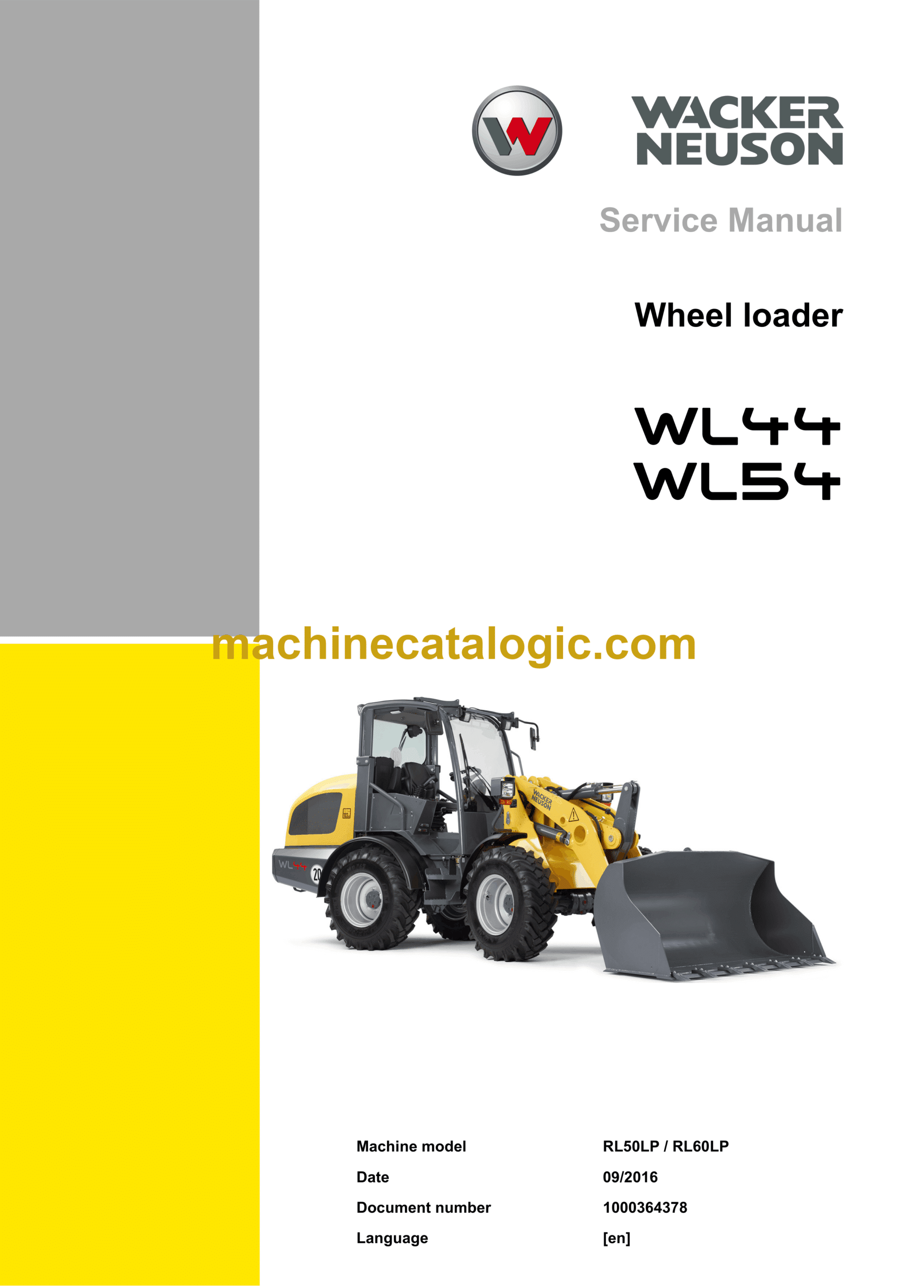
Brand: Wacker Neuson
Model: WL44, WL54 Loader
Type of Document: Service Manual
$ 45
Contents
E Introduction
E.1 Notice on this service manual
E.2 Technical data
E.3 Tightening torques
E.4 Safety instructions
E.5 Special tools
B Operation
B.1 Overview of control elements
B.2 Indicator lights and warning lights (overview)
1 Maintenance
1.1 Information on maintenance
1.2 Maintenance overview
1.3 Lubrication plan
1.4 Fluids and lubricants
1.5 Maintenance accesses
1.6 Cleaning and maintenance
1.7 Lubrication work
1.8 Fuel system
1.9 Engine lubrication system
1.10 Cooling system
1.11 Air filter
1.12 V-belt/toothed belt
1.13 Hydraulic system
1.14 Electrical system
1.15 Heating, ventilation and air conditioning system (option)
1.16 Washer system
1.17 Axles/traveling drive
1.18 Braking system
1.19 Tires
1.20 Maintenance and servicing work on attachments
1.21 Maintenance of options
1.22 Exhaust gas treatment
2 Engine
2.1 Perkins engine 404D-22 (35.7 kW)
2.2 Perkins engine 404F-22 (44.7 kW)
2.3 Alternator (44.7 kW)
2.4 Starter M001 (44.7 kW)
2.5 Diesel particulate filter (44.7 kW)
2.6 Deutz engine TCD 2.9 L4 (55.4 kW)
2.7 V-belts (55.4 kW)
2.8 Alternator (55.4 kW)
2.9 Removing/installing the starter (55.4 kW)
2.10 Removing/installing the air filter (55.4 kW)
2.11 Deutz engine TD2011 L04w (55.1 kW)
2.12 Removing/installing the fuel tank
3 Cooling
3.1 Removing/installing the coolant reservoir
3.2 Removing/installing the radiator
3.3 Removing/installing fan blades
4 Traveling drive
4.1 Traveling drive hose routing (example)
4.2 Variable displacement pump
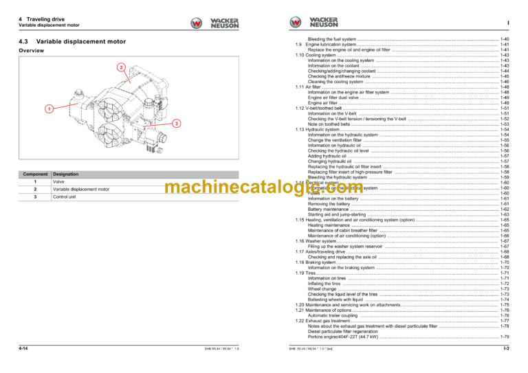
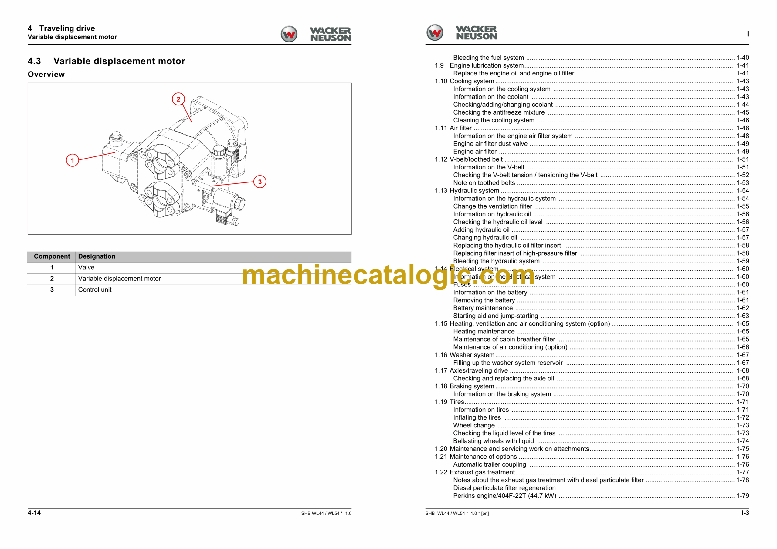
4.3 Variable displacement motor
4.4 Hydraulic oil reservoir
4.5 Removing/installing the cardan shaft
4.6 Troubleshooting
5 Axles
5.1 Front axle
5.2 Rear axle
5.3 Type label – front/rear axle
6 Brake
6.1 Removing/installing the brake pedal
6.2 Removing/installing the parking brake
6.3 Removing/installing the parking brake Bowden cable
6.4 Master brake cylinder
7 Steering system
7.1 Hose routing
7.2 Removing/installing the steering wheel
7.3 Removing/installing the steering column
7.4 Removing/installing steering column gas strut (Comfort Cabin)
7.5 Removing/installing steering cylinder A81
7.6 Steering orbitrol S1
7.7 Gear pump
8 Work hydraulics
8.1 Overview
8.2 Hose routing of lift, tilt and lock cylinders (WL44)
8.3 Hoses of lift and tilt cylinders with counterbalance valve
8.4 High Flow hose routing
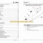
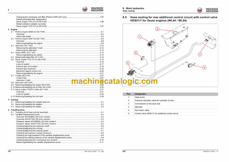
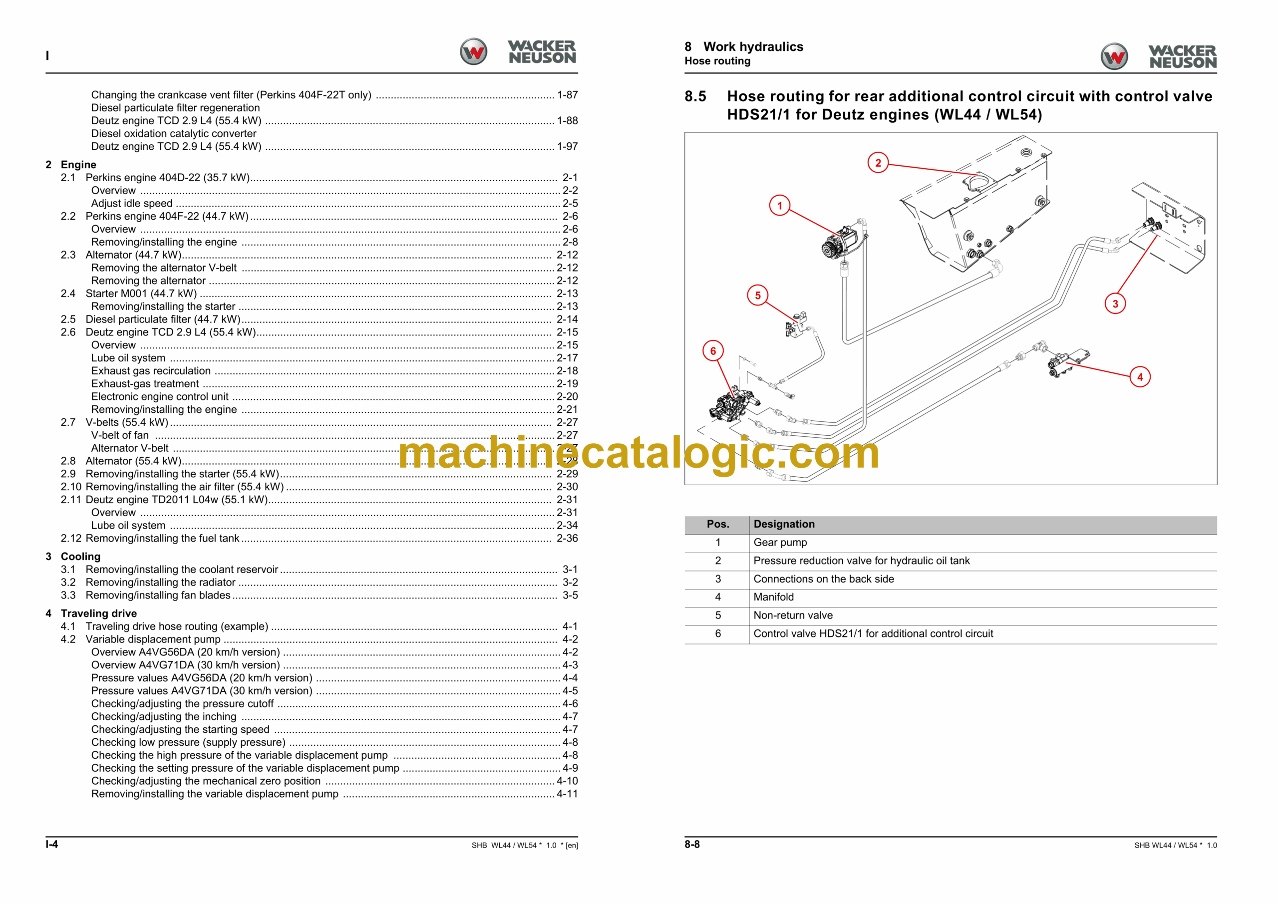
8.5 Hose routing for rear additional control circuit with control valve HDS21/1 for Deutz engines (WL44 / WL54)
8.6 Hose routing for rear additional control circuit with control valve HDS21/1 for Perkins engines (WL44)
8.7 Hose routing for rear additional control circuit with control valve HDS21/2 for Deutz engines (WL44 / WL54)
8.8 Hose routing for rear additional control circuit with control valve HDS21/2 for Perkins engines (WL44)
8.9 Removing/installing gear pump P43/P57
8.10 Removing/installing lock cylinder A4
8.11 Removing/installing the lock pin
8.12 Removing/installing the tilt cylinder
8.13 Removing/installing the loader unit
8.14 Removing/installing the lift cylinder
8.15 Removing/installing the reversing lever
8.16 Removing/installing solenoid valve V30
8.17 Removing/installing vibration damping valve V75
8.18 Removing/installing the quickhitch
8.19 Removing/installing operation lever for additional hydraulic system (control lever)
8.20 Control valve
8.21 Removing/installing control valve for additional hydraulics system
8.22 Designation of hydraulic components
8.23 Hydraulics diagram for wheel loaders WL44 – HDM19/4 with HDS21/1 or 6/2 directional valve
8.24 Hydraulics diagram for wheel loaders WL44 – HDM19/4 with HDS21/2
8.25 Hydraulics diagram for wheel loaders WL44 – HDM19/3 with HDS21/1 or 6/2 directional valve
8.26 Hydraulics diagram for wheel loaders WL44 – HDM19/4 High Flow
8.27 Hydraulics diagram for wheel loaders WL54 – HDM19/4 with HDS21/1 or 6/2 directional valve
8.28 Hydraulics diagram for wheel loaders WL54 – HDM19/4 with HDS21/2
8.29 Hydraulics diagram for wheel loaders WL54 – HDM19/3 with HDS21/1 or 6/2 directional valve
8.30 Hydraulics diagram for wheel loaders WL54 – HDM19/4 High Flow
9 Electrics
9.1 Fuses
9.2 Fuse assignment
9.3 Removing/installing the machine control unit
9.4 Joystick
9.5 Removing/installing the battery master switch
9.6 Malfunctions of the machine electronics
9.7 Electrical diagram – Electronics, power supply (FG01-01)
9.8 Electrical diagram – Electronics CAN Bus (FG01-02)
9.9 Electrical diagram – Perkins engine 404D-22 (FG02-01)
9.10 Electrical diagram – Perkins engine 404F-22 (FG02-02)
9.11 Electrical diagram – Perkins engine 404F-22 (FG02-03)
9.12 Electrical diagram – Deutz engine TD2011 (FG02-04)
9.13 Electrical diagram – Deutz engine TCD2.9 (FG02-05)
9.14 Electrical diagram – Deutz engine TCD2.9 (FG02-06)
9.15 Electrical diagram – Deutz engine TCD2.9 DPF (FG02-07)
9.16 Electrical diagram – Deutz engine TCD2.9 DPF (FG02-08)
9.17 Electrical diagram – Deutz engine TCD2.9 DPF (FG02-09)
9.18 Electrical diagram – Instrument (FG03-01)
9.19 Electrical diagram – Drive function (FG04-01)
9.20 Electrical diagram – manual throttle, manual inching (FG04-02)
9.21 Electric circuit diagram – Working lights; Rotating beacon; Horn (FG05-01)
9.22 Electric circuit diagram – Light StVZO (German traffic regulations) (turn indicator system, horn) (FG06-01)
9.23 Electric circuit diagram – Light StVZO (German traffic regulations) (front headlight) (FG06-02)
9.24 Electric circuit diagram – Light (brake light, reversing light) (FG06-03)
9.25 Electrical diagram – Washer system (FG07-01)
9.26 Electric circuit diagram – Radio, cigarette lighter, interior light (FG08-01)
9.27 Electric circuit diagram – Heating; Seat (FG09-01)
9.28 Electric circuit diagram – Heating; Air conditioning system (FG09-02)
9.29 Electric circuit diagram – Hydraulic control circuits, E-connection 12 V (FG10-01)
9.30 Electric circuit diagram – Hydraulic control circuits, rear E-connection (FG11-01)
9.31 Electrical diagram – High Flow (FG11-02)
9.32 Electric circuit diagram – Roll-in stop; Overload display (FG11-03)
9.33 Electrical diagram – Loader unit stabilizer, counterbalance valve (FG11-04)
9.34 Electrical diagram – Central lubrication system (FG12-01)
9.35 Designation of electrical components
10 Trim
10.1 Removing/installing the engine cover
10.2 Removing/installing the base plate
10.3 Removing/installing the trailer power outlet
10.4 Removing/installing the trailer coupling/chassis cover
10.5 Removing/installing the counterweight
10.6 Base weights (WL54)
11 Cabin
11.1 Removing/installing the floor mat
11.2 Removing/installing the steering wheel
11.3 Removing/installing the indicating instrument
11.4 Removing/installing the starter
11.5 Removing/installing the wiper motor
11.6 Heating
11.7 Removing/installing the cabin
11.8 Removing/installing the base plate
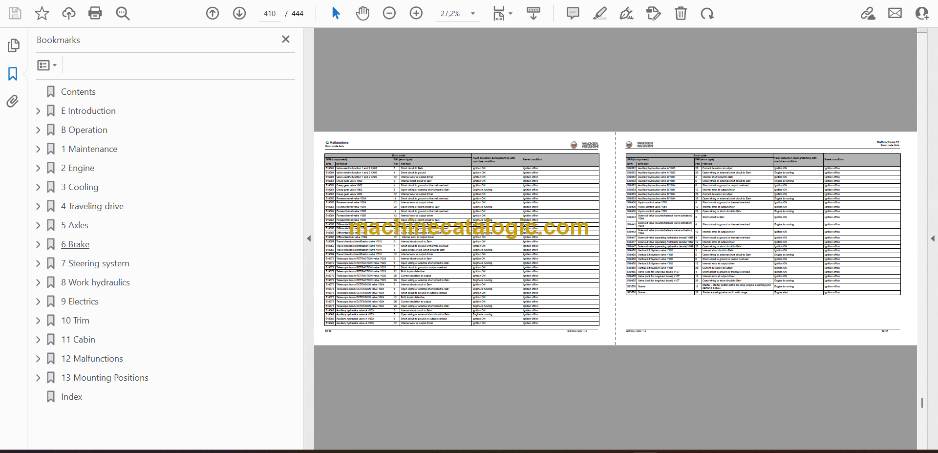
12 Malfunctions
12.1 Towing a machine
12.2 Error code lists
13 Mounting Positions
13.1 Hydraulics
13.2 Electrics
Index
