Format: PDF
Language: EN
Size: 80.57 MB
Pages: 530
Speed Download Link
$ 50 Original price was: $ 50.$ 40Current price is: $ 40.
YANMAR B7-3 SERVICE MANUAL contains high quality images, diagrams, instructions to help you to operate, maintenance, diagnostic, and repair your machine. This document is printable, without restrictions, contains searchable text and bookmarks for easy navigation.
GENERAL CAUTIONS FOR MAINTENANCE WORK
1-1 Correct Work ………………………………………………………………………………………………………………………………………………………1-1
1-2 Safety Precautions ………………………………………………………………………………………………………………………………………………1-1
1-3 Preparations……………………………………………………………………………………………………………………………………………………….1-1
1-4 Cautions for Disassembly and Reassembly…………………………………………………………………………………………………………….1-1
1-5 Cautions for Removal and Installation of Hydraulic Equipment ………………………………………………………………………………….1-2
1-6 Cautions for Removal and Installation of Hydraulic Piping…………………………………………………………………………………………1-2
1-7 Cautions for Handling Seals………………………………………………………………………………………………………………………………….1-3
1-8 Correct Installation of Hydraulic Hose…………………………………………………………………………………………………………………….1-3
1-9 Specifications of Hydraulic Hose……………………………………………………………………………………………………………………………1-6
1-10 Air Release of Hydraulic Equipment……………………………………………………………………………………………………………………1-11
CHAPTER 2
TECHNICAL DATA
2-1 Specifications …………………………………………………………………………………………………………………………………………………. 2-1-1
2-2 Outline Drawing and Working Area……………………………………………………………………………………………………………………. 2-2-1
2-2-1 Canopy type …………………………………………………………………………………………………………………………………………… 2-2-1
2-2-2 Cabin type ……………………………………………………………………………………………………………………………………………… 2-2-2
2-3 Weight List of Main Parts …………………………………………………………………………………………………………………………………. 2-3-1
2-4 Lifting Capacity List (For Standard Arm) …………………………………………………………………………………………………………….. 2-4-1
CHAPTER 3
SERVICE STANDARDS
3-1 Machine Performance …………………………………………………………………………………………………………………………………….. 3-1-1
3-2 Engine …………………………………………………………………………………………………………………………………………………………… 3-2-1
3-3 Undercarriage ………………………………………………………………………………………………………………………………………………… 3-3-1
3-3-1 Rubber Crawler Specifications ………………………………………………………………………………………………………………….. 3-3-1
3-3-2 Steel Crawler Specifications……………………………………………………………………………………………………………………… 3-3-2
3-3-3 Common Specifications of Steel & Rubber Crawlers ……………………………………………………………………………………. 3-3-3
3-4 Controls…………………………………………………………………………………………………………………………………………………………. 3-4-1
3-5 Hydraulic Equipment ……………………………………………………………………………………………………………………………………….. 3-5-1
3-5-1 Hydraulic Cylinders …………………………………………………………………………………………………………………………………. 3-5-1
3-6 Implement ……………………………………………………………………………………………………………………………………………………… 3-6-1
3-6-1 Front Attachments …………………………………………………………………………………………………………………………………… 3-6-1
3-6-2 Blade Moving Device……………………………………………………………………………………………………………………………….. 3-6-2
3-6-3 Bucket Teeth ………………………………………………………………………………………………………………………………………….. 3-6-2
3-7 List of Tightening Torque …………………………………………………………………………………………………………………………………. 3-7-1
3-7-1 Machine…………………………………………………………………………………………………………………………………………………. 3-7-1
3-7-2 Engine …………………………………………………………………………………………………………………………………………………… 3-7-4
3-7-3 Tightening Torque for General Bolts and Nuts…………………………………………………………………………………………….. 3-7-4
CHAPTER 4
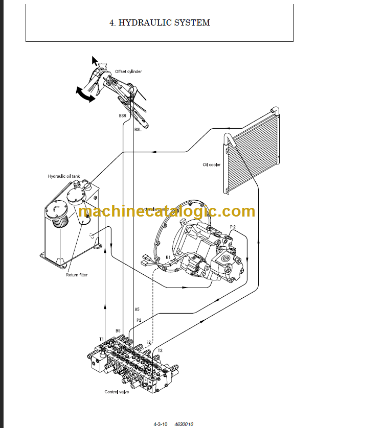
HYDRAULIC SYSTEM
4-1 Outline…………………………………………………………………………………………………………………………………………………………… 4-1-1
4-1-1 Control Valve Operation …………………………………………………………………………………………………………………………… 4-1-4
4-1-2 Additional Operation of Control Valve ………………………………………………………………………………………………………… 4-1-6
4-2 Hydraulic Circuit Schematic ……………………………………………………………………………………………………………………………… 4-2-1
4-2-1 Standard Specifications……………………………………………………………………………………………………………………………. 4-2-1
4-3 Circuit Operation …………………………………………………………………………………………………………………………………………….. 4-3-1
4-3-1 Boom…………………………………………………………………………………………………………………………………………………….. 4-3-1
4-3-2 Arm……………………………………………………………………………………………………………………………………………………….. 4-3-3
4-3-3 Bucket …………………………………………………………………………………………………………………………………………………… 4-3-5
4-3-4 Swing…………………………………………………………………………………………………………………………………………………….. 4-3-7
4-3-5 Boom Offset …………………………………………………………………………………………………………………………………………… 4-3-9
4-3-6 Blade …………………………………………………………………………………………………………………………………………………… 4-3-11
4-3-7 Travel ………………………………………………………………………………………………………………………………………………….. 4-3-13
4-3-8 Simultaneous Operation of Travel and Boom / Bucket ……………………………………………………………………………….. 4-3-15
4-3-9 Simultaneous Operation of Travel and Arm / Boom Offset ………………………………………………………………………….. 4-3-17
4-3-10 Simultaneous Operation of Boom Up and Arm Retract……………………………………………………………………………… 4-3-19
4-3-11 Simultaneous Operation of Boom Up and Bucket…………………………………………………………………………………….. 4-3-21
4-3-12 Simultaneous Operation of Boom Up and Swing ……………………………………………………………………………………… 4-3-23
4-3-13 Hydraulic P.T.O. ………………………………………………………………………………………………………………………………….. 4-3-25
4-4 Pressure Adjustment ……………………………………………………………………………………………………………………………………….. 4-4-1
4-4-1 Relief Valves ………………………………………………………………………………………………………………………………………….. 4-4-1
4-4-2 Swing Brake Valve ………………………………………………………………………………………………………………………………….. 4-4-3
4-4-3 Cut-off Valve…………………………………………………………………………………………………………………………………………… 4-4-4
CHAPTER 5
HYDRAULIC EQUIPMENT
5-1 Hydraulic Pump………………………………………………………………………………………………………………………………………………. 5-1-1
5-2 Control Valve………………………………………………………………………………………………………………………………………………….. 5-2-1
5-3 Pilot Valve ……………………………………………………………………………………………………………………………………………………… 5-3-1
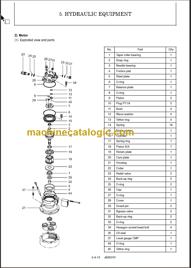
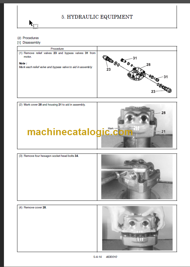
5-4 Swing Motor …………………………………………………………………………………………………………………………………………………… 5-4-1
5-5 Travel Motor …………………………………………………………………………………………………………………………………………………… 5-5-1
CHAPTER 6
ADJUSTMENT AND REPAIR
6-1 Electric Equipment of the Machine…………………………………………………………………………………………………………………….. 6-1-1
6-1-1 Parts Layout of Electrical Equipment …………………………………………………………………………………………………………. 6-1-1
6-1-2 Monitor and Alarm Systems ……………………………………………………………………………………………………………………… 6-1-4
6-1-3 Wiring Diagram……………………………………………………………………………………………………………………………………….. 6-1-7
6-1-4 Stop Motor Operation ………………………………………………………………………………………………………………………………. 6-1-9
6-1-5 Removal and Reinstallation of Engine ……………………………………………………………………………………………………… 6-1-13
6-1-6 Removal and Reassembly of Starter Motor ………………………………………………………………………………………………. 6-1-22
6-2 Undercarriage ………………………………………………………………………………………………………………………………………………… 6-2-1
6-2-1 Outline …………………………………………………………………………………………………………………………………………………… 6-2-1
6-2-2 Main Parts ……………………………………………………………………………………………………………………………………………… 6-2-1
6-2-3 Points of Reassembly (Rubber Crawler) …………………………………………………………………………………………………….. 6-2-2
6-2-4 Points of Reassembly (Steel Crawler)………………………………………………………………………………………………………… 6-2-3
6-2-5 Disassembly and Reassembly of Steel Crawler…………………………………………………………………………………………… 6-2-4
6-2-6 Disassembly and Reassembly of Idler ……………………………………………………………………………………………………….. 6-2-6
6-2-7 Disassembly and Reassembly of Track Roller…………………………………………………………………………………………….. 6-2-9
6-2-8 Disassembly and Reassembly of Carrier Roller …………………………………………………………………………………………. 6-2-11