————————-
Format: PDF (Printable Document)
File Language: English
File Pages: 136
File Size: 3.72 MB (Speed Download Link)
Brand: Yanmar
Model: Model TNE Series Industrial Diesel Engine
Type of Document: Service Manual
$ 39
Specifications and Performance •..•……………….•.•…•.•…..••••….•••.•.•………..•…….•.•…•.•. 1-1
1-1 2TNE68……………………………………………………………………………………………….. 1-1
1-2 3TNE68 …. …. ………………….. …………………. ………………………………………………… 1-2
1-3 3TNE74 ……………………………………………………………………………………………….. 1-3
1-4 3TNE78A .. …………………………… …….. ………… …………………….. …….. ………. …….. 1-4
1-5 3TNE82A …………………………………………………………………………………………….. 1-5
1-6 3TNE82 ……………………………………………………………………………………………….. 1-6
1-7 3TNE84……………………………………………………………………………………………….. 1-7
1-8 3TNE88 ……………………………………………………………………………………………….. 1-8
1-9 4TNE82……………………………………………………………………………………………….. 1-9
1-10 4TNE84……………………………………………………………………………………………….. 1-10
1-11 4TNE88……………………………………………………………………………………………….. 1-11
1-12 3TNE84T……………………………………………………………………………………………… 1-12
1-13 4TNE84T……………………………………………………………………………………………… 1-13
2. Cross Sectional Views ……………..•………••.•..•••.•••…•………..•…….•…•••••….•…•…•…..•…..•. 2-1
2-1 Special Swirl Pre-combustion Chamber System ……………………………………….. 2-1
2-2 Direct Injection System………. ………………………….. …… …….. ………………………… 2-2
3. Cooling Water, Lubricating Oil and Fuel Oil …………………………………………………….. 3-1
3-1 Cooling water ……………………………………………………………………………………….. 3-1
3-2 lubricating oil…………………………………. ……………………………………………………. 3-1
3-3 Fuel oil ……………….. …………. ………….. ………….. ………….. ….. …………………………. 3-3
4. Troubleshooting ……………………………………………………………………………………………… 4-1
4-1 Trouble causes and remedies…………………………………………………………………. 4-1
4-2 Trouble diagnosis through measurement of compression pressure ……………… 4-3
5. Special Service Tools and Measuring Instruments …………………………………………… 5-1
5-1 Special service tools………. …………………. ………………… ……………….. ………… ….. 5-1
5-2 Measuring instruments …………………………………………………………………………… 5-3
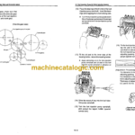
6. Measurement, Inspection and Adjustment ………………………………………………………. 6-1
6-1 Measuring the compression pressure ……… …………….. ……………. ………. ………… 6-1
6-2 Adjusting the valve head clearance ……………… …………………………………………. 6-3
6-3 Checking the V -belt tension …… ……………………….. ……………. ………………………. 6-4
6-4 Measuring and checking the injection pressure and spray patterns
of the fuel injection valve ……………………………………. ……………………… ………….. 6-4
6-5 Checking and adjusting the fuel injection timing ………………………………………… 6-8
6-6 Adjusting the no-load maximum (or minimum) revolutions ………………………….. 6-10
6-7 Checking the COOling water system and radiator for water leakage ……………… 6-10
6-8 Checking the battery ……………………….. ……………………………………………………. 6-11
6-9 Checking sensors …………………………………………………………………………………. 6-13
6-10 Checking the oil cooler …………………………………………………………………………… 6-14
6-11 Checking the piston cooling nozzle …………………………………………………………. 6-15
7. Measuring Procedures, Service Data and Corrective Action …………………………….. 7-1
7-1 Cylinder head … …… ……..•……… …… …………………. …….. …….. … ……….. …….. …….. 7-1
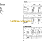
7-2 Cylinder block ………………………………………………………………………………………. 7-7
7-3 Valve rocker arm….. …….. …… ………. …… ………….. ……………………………………….. 7-10
7-4 Piston and piston ring …… …………………. ……………………………. …….. ……………… 7-12
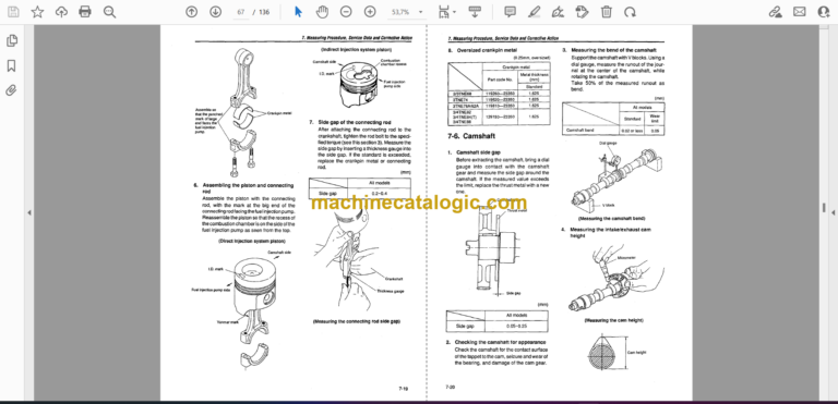
7·5 Connecting rod……………. ………… ………. …………. …………. …………………………….. 7-17
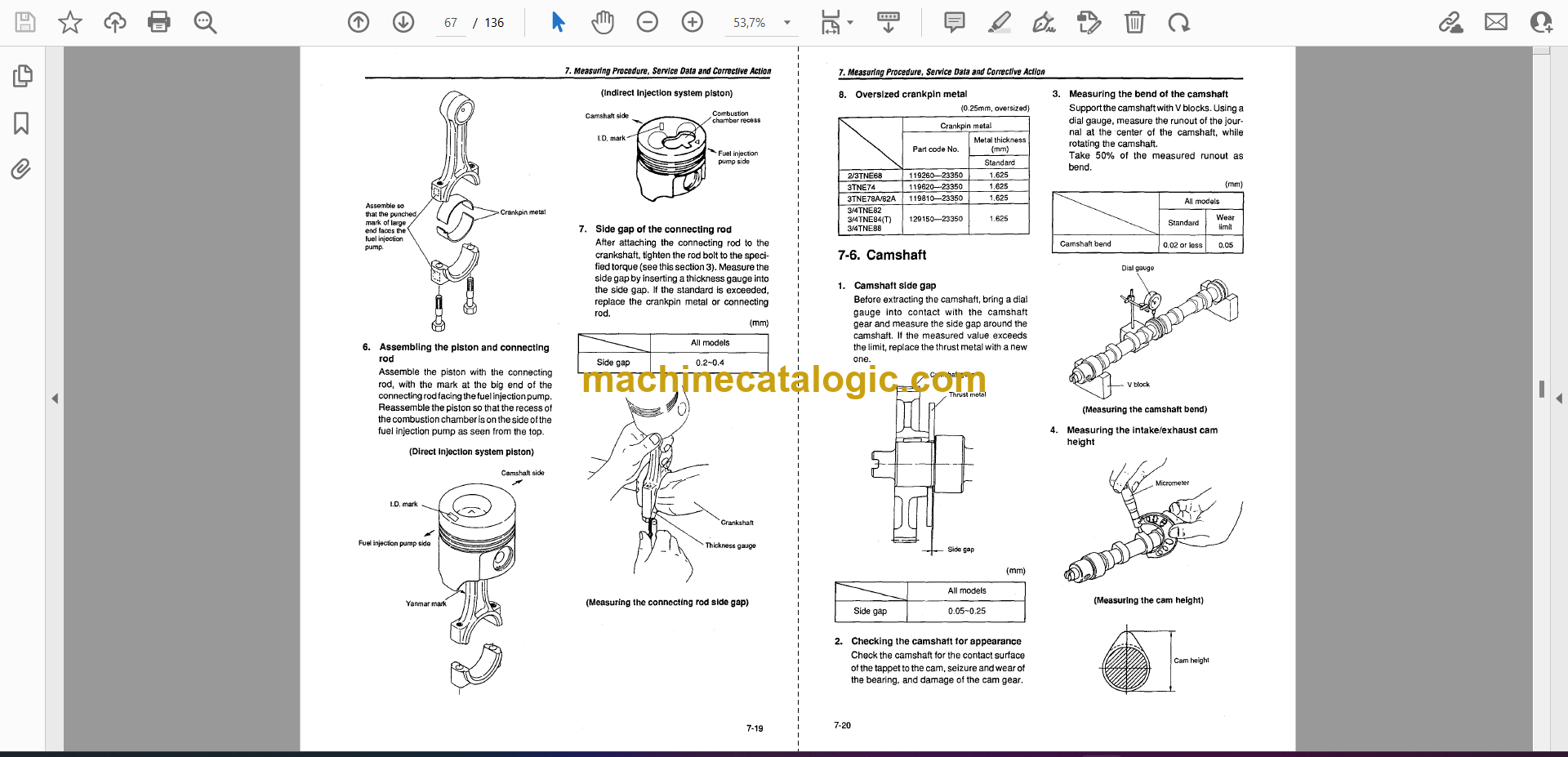
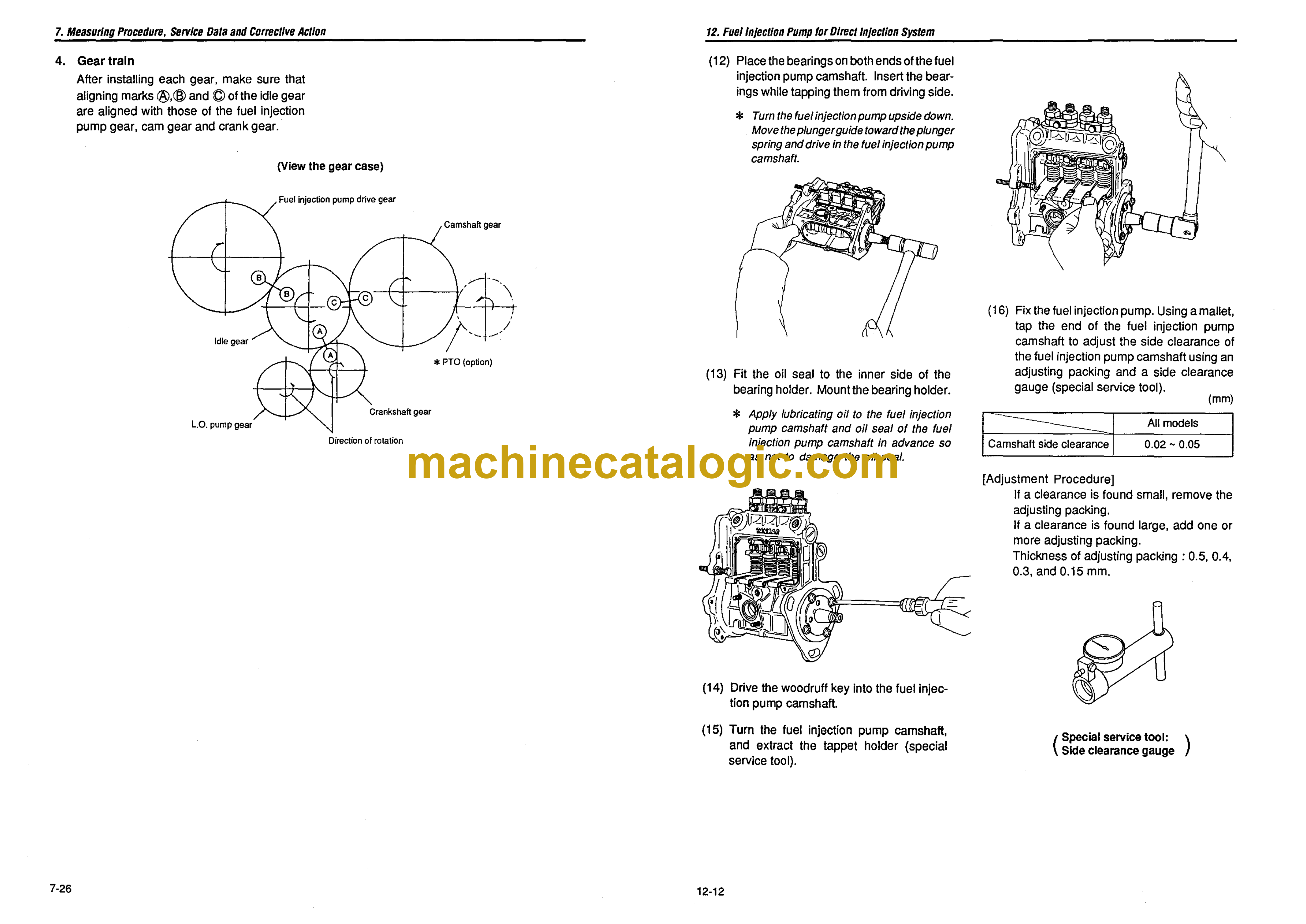
7-6 Camshaft……………………………………………………………………………………………… 7-20
7-7 Crankshaft……………………………………………………………………………………………. 7-22
7-8
7-9
Gears …………………………………………………………………………………………………. .
Trochoid pump ……………………………………………………………………………………. ..
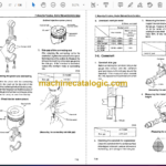
8. Disassembly and Reassembly ………………………………………………………………………… .
8-1 Disassembly ………………………………………………………………………………………… .
8-2 Precautions before and during reassembly …………………………………………….. ..
9. Service Data ………………………………………………………………………………………………….. .
9-1 Cylinder head ……………………………………………………………………………………… ..
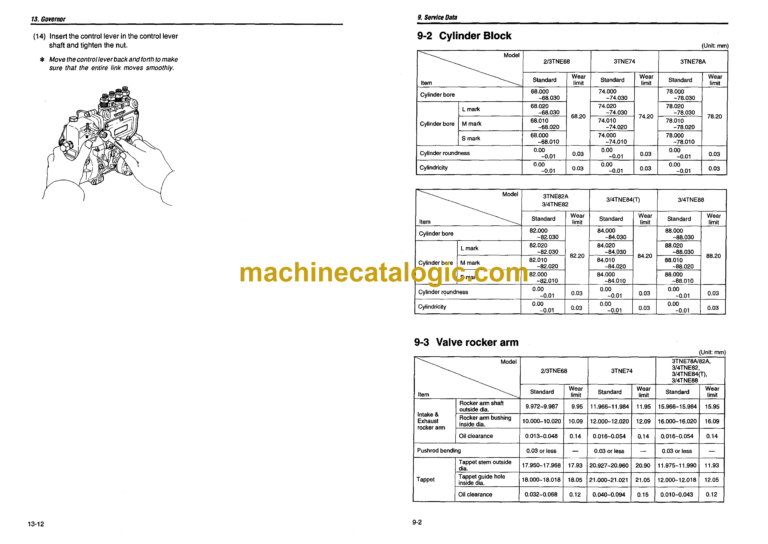
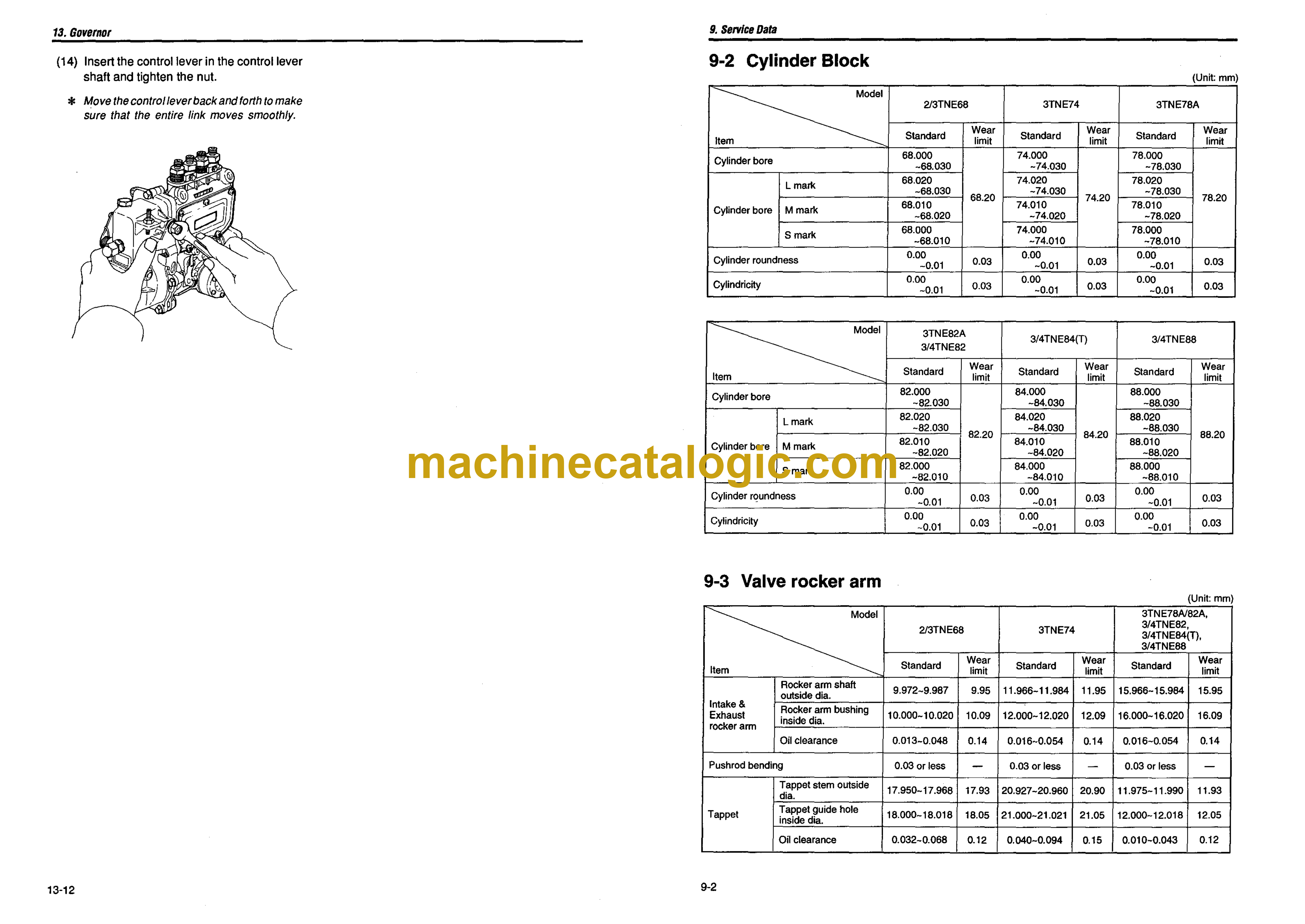
9-2 Cylinder block ……………………………………………………………………………………… .
9-3 Valve rocker arm ………………………………………………………………………………….. .
9-4 Piston …………………………………………………………………………………………………. .
9-5 Piston ring ………………………………………………………………………………………….. ..
9-6 Connecting rod ……………………………………………………………………………………. ..
9-7 Camshaft …………………………………………………………………………………………….. .
9-8 Crankshaft ………………………………………………………………………………………….. ..
9-9 Side gap and backlash …………………………………………………………………………… 9-6
9-1 0 Others …………………………………………………………………………………………………. 9-6
10. Tightening Torque ………………………………………………………………………………………….. 10-1
10-1 Main bolVnut ………………………………………………………………………………………… 10-1
10-2 Standard bolt and nut.. ……………… …… ………………… …………………………………… 10-1
11. Fuel Injection Pump for Indirect Injection System ……………………………………………. 11-1
11·1 Exploded views (YPFR type) .. …….. …….. ……………. ….. ………… …….. ….. … …… .•.. 11-1
11-2 Disassembly …………………………………………………………………………………………. 11-2
11·3 Inspection……… …………………………………………………………………………………….. 11-3
11-4 Reassembly ………………………… ………………. …………….. ……….. …………. …………. 11-5
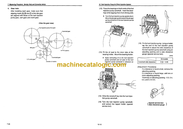
12. Fuel Injection Pump for Direct Injection System ………………………………………………. 12-1
12-1 Exploded Views (YPES type)………………………………………………………………….. 12·1
12-2 Special service tools for disassembly and reassembly…. ……………………………. 12·2
12-3 Disassembly…………………….. …….. ……………………………………………………… …… 12-3
12-4 Inspection…………………………………………………………………………………………….. 12-7
12-5 Reassembly …………………………………………………. ……………………. …….. …… …… 12·9
13. Governor …………………………………………………………………………….. …….. ………………….. 13·1
13-1 Exploded views of governorfor indirect injection system … …………………………. 13-1
13-2 Exploded views of governor for direct injection system ………………………………. 13-2
13-3 Disassembly……………. ……………………….. ….. …. …………………….. ….. ……….. ……. 13-3
13-4 Inspection…………………………………………………………………………………………….. 13-7
13-5 Reassembly…. ……. …… …… ……………….. …….. ……….. …………….. ……………. …. …. 13-9
14. Turbocharger ………………………………………………………………………………………………….. 14·1
14-1 Specifications ……………………………………………………………………………………….. 14·1
14-2 Construction …………………………………………………………………………………………. 14-1
14-3 Waste gate valve adjusting method …. …. …. …….. …… …. ……………. ….. ……… ……. 14-3
14·4 Exploded view of Turbocharger (wI waste gate) .. … …….. …. …. ………… ………. ….. 14-5
14-5 Tightening torque ……………………….. ……………. ……….. ………… ……………………… 14-6
14-6 Service standards ……………………………………………………………………….. ……….. 14-6
15. Service Information for CARS ULG regulation …………………………………………………. 15·1
15-1 Emission control labels ……………………………………………………………………….. :.. 15-1
15-2 Limiting the high idle and low idle adjustment screw………………………………….. 15-6
15-3 Limiting the fuel volume limiter screw…. …………………………………………………… 15-7
Attached Drawing 1. Exploded Views of Engine Components ………………………………. A·1
Attached Drawing 2. Exploded Views of Engine Components ………………………………. A·2
