Format: PDF
Language: EN
Size: 110.65 MB
Pages: 469
Speed Download Link
$ 50 Original price was: $ 50.$ 40Current price is: $ 40.
YANMAR VIO26-6 SERVICE MANUAL contains high quality images, diagrams, instructions to help you to operate, maintenance, diagnostic, and repair your machine. This document is printable, without restrictions, contains searchable text and bookmarks for easy navigation.
CHAPTER 1
GENERAL CAUTIONS FOR MAINTENANCE WORK
1-1 Correct Work ………………………………………………………………………………………………………………………………………………………1-1
1-2 Safety Precautions ………………………………………………………………………………………………………………………………………………1-1
1-3 Preparations……………………………………………………………………………………………………………………………………………………….1-1
1-4 Cautions for Disassembly and Reassembly…………………………………………………………………………………………………………….1-1
1-5 Cautions for Removal and Installation of Hydraulic Equipment ………………………………………………………………………………….1-2
1-6 Cautions for Removal and Installation of Hydraulic Piping…………………………………………………………………………………………1-2
1-7 Cautions for Handling Seals………………………………………………………………………………………………………………………………….1-3
1-8 Correct Installation of Hydraulic Hose …………………………………………………………………………………………………………………….1-3
1-9 Specifications of Hydraulic Hose……………………………………………………………………………………………………………………………1-6
1-10 Air Release of Hydraulic Equipment……………………………………………………………………………………………………………………..1-8
CHAPTER 2
TECHNICAL DATA
2-1 Specifications …………………………………………………………………………………………………………………………………………………. 2-1-1
2-2 Outline Drawing and Working Area……………………………………………………………………………………………………………………. 2-2-1
2-3 Weight List of Main Parts …………………………………………………………………………………………………………………………………. 2-3-1
2-4 Lifting Capacity List …………………………………………………………………………………………………………………………………………. 2-4-1
2-5 Specifications for Attachment……………………………………………………………………………………………………………………………. 2-5-1
2-6 Periodic Inspection and Servicing ……………………………………………………………………………………………………………………… 2-6-1
2-7 Fuel, Lube Oil and Grease Recommended…………………………………………………………………………………………………………. 2-7-1
2-8 Hydraulic Circuit Schematic ……………………………………………………………………………………………………………………………… 2-8-1
2-9 Wiring Diagram……………………………………………………………………………………………………………………………………………….. 2-9-1
CHAPTER 3
SERVICE STANDARDS
3-1 Machine Performance ……………………………………………………………………………………………………………………………………… 3-1-1
3-2 Engine …………………………………………………………………………………………………………………………………………………………… 3-2-1
3-3 Undercarriage ………………………………………………………………………………………………………………………………………………… 3-3-1
3-3-1 Rubber Track Specifications …………………………………………………………………………………………………………………….. 3-3-1
3-3-2 Steel Track Specifications ………………………………………………………………………………………………………………………… 3-3-2
3-3-3 Common Specifications of Steel & Rubber Crawlers ……………………………………………………………………………………. 3-3-4
3-4 Controls…………………………………………………………………………………………………………………………………………………………. 3-4-1
3-5 Hydraulic Equipment ……………………………………………………………………………………………………………………………………….. 3-5-1
3-5-1 Hydraulic Cylinders …………………………………………………………………………………………………………………………………. 3-5-1
3-6 Implement ……………………………………………………………………………………………………………………………………………………… 3-6-1
3-6-1 Front Attachments …………………………………………………………………………………………………………………………………… 3-6-1
3-6-2 Blade Moving Device……………………………………………………………………………………………………………………………….. 3-6-2
3-7 List of Tightening Torque …………………………………………………………………………………………………………………………………. 3-7-1
3-7-1 Machine…………………………………………………………………………………………………………………………………………………. 3-7-1
3-7-2 Engine …………………………………………………………………………………………………………………………………………………… 3-7-5
3-7-3 Tightening Torque for General Bolts and Nuts…………………………………………………………………………………………….. 3-7-6
3-7-4 Hydraulic Fitting………………………………………………………………………………………………………………………………………. 3-7-7
3-8 Pressure Adjustment……………………………………………………………………………………………………………………………………….. 3-8-1
3-8-1 Relief Valves ………………………………………………………………………………………………………………………………………….. 3-8-1
3-8-2 Swing Brake Valve ………………………………………………………………………………………………………………………………….. 3-8-4
3-8-3 Cut-Off Valve………………………………………………………………………………………………………………………………………….. 3-8-5
CHAPTER 4
ENGINE
4-1 Safety ……………………………………………………………………………………………………………………………………………………………. 4-1-1
4-1-1 Safety Statements …………………………………………………………………………………………………………………………………… 4-1-1
4-1-2 Safety Precautions ………………………………………………………………………………………………………………………………….. 4-1-2
4-2 Engine …………………………………………………………………………………………………………………………………………………………… 4-2-1
4-2-1 Before You Begin Servicing ……………………………………………………………………………………………………………………… 4-2-1
4-2-2 Special Service Tools………………………………………………………………………………………………………………………………. 4-2-2
4-2-3 Measuring Instruments…………………………………………………………………………………………………………………………….. 4-2-4
4-2-4 Cylinder Head…………………………………………………………………………………………………………………………………………. 4-2-6
4-2-5 Measuring and Adjusting Valve Clearance ……………………………………………………………………………………………….. 4-2-20
4-2-6 Crankshaft and Camshaft Components ……………………………………………………………………………………………………. 4-2-22
4-3 Fuel System …………………………………………………………………………………………………………………………………………………… 4-3-1
4-3-1 Before You Begin Servicing ……………………………………………………………………………………………………………………… 4-3-1
4-3-2 Introduction…………………………………………………………………………………………………………………………………………….. 4-3-2
4-3-3 Special Service Tools………………………………………………………………………………………………………………………………. 4-3-4
4-3-4 Measuring Instruments…………………………………………………………………………………………………………………………….. 4-3-4
4-3-5 Fuel System Diagram………………………………………………………………………………………………………………………………. 4-3-5
4-3-6 Fuel System Components ………………………………………………………………………………………………………………………… 4-3-6
4-3-7 Fuel Injection Lines …………………………………………………………………………………………………………………………………. 4-3-7
4-3-8 Fuel Injection Pump…………………………………………………………………………………………………………………………………. 4-3-9
4-3-9 Checking and Adjusting Fuel Injection Timing …………………………………………………………………………………………… 4-3-15
4-3-10 Fuel Injectors……………………………………………………………………………………………………………………………………… 4-3-18
4-4 Cooling System………………………………………………………………………………………………………………………………………………. 4-4-1
4-4-1 Before You Begin Servicing ……………………………………………………………………………………………………………………… 4-4-1
4-4-2 Introduction…………………………………………………………………………………………………………………………………………….. 4-4-2
4-4-3 Cooling System Diagram………………………………………………………………………………………………………………………….. 4-4-2
4-4-4 Engine Coolant Pump Components …………………………………………………………………………………………………………… 4-4-3
4-4-5 Engine Coolant System Check………………………………………………………………………………………………………………….. 4-4-4
4-4-6 Engine Coolant Pump ……………………………………………………………………………………………………………………………… 4-4-4
4-5 Lubrication System………………………………………………………………………………………………………………………………………….. 4-5-1
4-5-1 Before You Begin Servicing ……………………………………………………………………………………………………………………… 4-5-1
4-5-2 Introduction…………………………………………………………………………………………………………………………………………….. 4-5-2
4-5-3 Lubrication System Diagram …………………………………………………………………………………………………………………….. 4-5-2
4-5-4 Checking Engine Oil Pressure ………………………………………………………………………………………………………………….. 4-5-3
4-5-5 Trochoid Oil Pump…………………………………………………………………………………………………………………………………… 4-5-3
4-6 Starter Motor ………………………………………………………………………………………………………………………………………………….. 4-6-1
4-6-1 Before You Begin Servicing ……………………………………………………………………………………………………………………… 4-6-1
4-6-2 Introduction…………………………………………………………………………………………………………………………………………….. 4-6-2
4-6-3 Starter Motor Specifications ……………………………………………………………………………………………………………………… 4-6-2
4-6-4 Starter Motor Troubleshooting…………………………………………………………………………………………………………………… 4-6-3
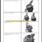
4-6-5 Starter Motor Components ……………………………………………………………………………………………………………………….. 4-6-4
4-6-6 Starter Motor ………………………………………………………………………………………………………………………………………….. 4-6-5
4-7 Alternator……………………………………………………………………………………………………………………………………………………….. 4-7-1
4-7-1 Before You Begin Servicing ……………………………………………………………………………………………………………………… 4-7-1
4-7-2 Introduction…………………………………………………………………………………………………………………………………………….. 4-7-2
4-7-3 Alternator Specifications…………………………………………………………………………………………………………………………… 4-7-2
4-7-4 Alternator Troubleshooting ……………………………………………………………………………………………………………………….. 4-7-3
4-7-5 Alternator Components ……………………………………………………………………………………………………………………………. 4-7-4
4-7-6 Alternator Wiring Diagram ………………………………………………………………………………………………………………………… 4-7-5
4-7-7 Alternator Standard Output ………………………………………………………………………………………………………………………. 4-7-6
4-7-8 Alternator……………………………………………………………………………………………………………………………………………….. 4-7-7
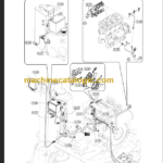
4-8 Electric Wiring ……………………………………………………………………………………………………………………………………………….. 4-8-1
4-8-1 Electric Wiring Precautions ……………………………………………………………………………………………………………………… 4-8-1
4-9 Troubleshooting ……………………………………………………………………………………………………………………………………………… 4-9-1
4-9-1 Special Service Tools………………………………………………………………………………………………………………………………. 4-9-1
4-9-2 Troubleshooting By Measuring Compression Pressure ………………………………………………………………………………… 4-9-2
4-9-3 Quick Reference Table For Troubleshooting ………………………………………………………………………………………………. 4-9-4
CHAPTER 5
ELECTRIC SYSTEM
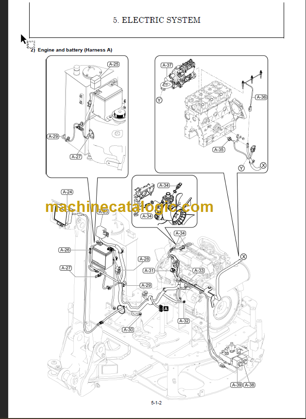
5-1 Electric Equipment of Machine………………………………………………………………………………………………………………………….. 5-1-1
5-1-1 Parts Layout of Electrical Equipment …………………………………………………………………………………………………………. 5-1-1
5-1-2 LCD Monitor and Alarm Systems ……………………………………………………………………………………………………………… 5-1-5
5-2 Circuit Description of Engine Start and Stop……………………………………………………………………………………………………….. 5-2-1
5-2-1 Engine Start and Stop ……………………………………………………………………………………………………………………………… 5-2-1
5-2-2 Battery charge ………………………………………………………………………………………………………………………………………… 5-2-3
5-3 Automatic Deceleration System ………………………………………………………………………………………………………………………… 5-3-1
5-3-1 Main Components and Wiring Diagram ……………………………………………………………………………………………………… 5-3-1
5-3-2 Function and Control ………………………………………………………………………………………………………………………………. 5-3-4
5-3-3 Error Indication of Auto Deceleration Alarm Lamp ………………………………………………………………………………………. 5-3-4
5-4 Error Code List ……………………………………………………………………………………………………………………………………………….. 5-4-1
CHAPTER 6
HYDRAULIC SYSTEM
6-1 Outline…………………………………………………………………………………………………………………………………………………………… 6-1-1
6-1-1 Control Valve Operation …………………………………………………………………………………………………………………………… 6-1-3
6-2 Circuit Operation …………………………………………………………………………………………………………………………………………….. 6-2-1
6-2-1 Boom …………………………………………………………………………………………………………………………………………………….. 6-2-1
6-2-2 Arm……………………………………………………………………………………………………………………………………………………….. 6-2-2
6-2-3 Bucket …………………………………………………………………………………………………………………………………………………… 6-2-3
6-2-4 Swing…………………………………………………………………………………………………………………………………………………….. 6-2-4
6-2-5 Boom Swing …………………………………………………………………………………………………………………………………………… 6-2-5
6-2-7 Blade …………………………………………………………………………………………………………………………………………………… 6-2-7
6-2-8 Travel ………………………………………………………………………………………………………………………………………………….. 6-2-8
6-2-6 P.T.O …………………………………………………………………………………………………………………………………………………… 6-2-6
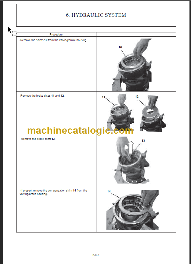
6-3 Hydraulic Pump………………………………………………………………………………………………………………………………………… 6-3-1
6-4 Control Valve……………………………………………………………………………………………………………………………………………. 6-4-1
6-5 Pilot Valve ……………………………………………………………………………………………………………………………………………….. 6-5-1
6-6 Swing Motor …………………………………………………………………………………………………………………………………………….. 6-6-1