$ 0
0
$ 0
0

Airman AX48U-6A (Hitachi ZX48U-5A) Hydraulic Excavator Technical Manual and Circuit Diagrams

Format: PDF (Printable Document)

File Language: English

File Pages: 404

File Size: 5.14 MB (Speed Download Link)

Brand: Airman (Hitachi)

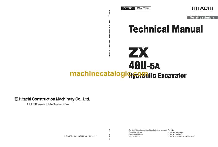
Model: AX48U-6A (Hitachi ZX48U-5A) Hydraulic Excavator Technical Manual and

Type of Document: Technical Manual and Circuit Diagrams

Categories: , ,

$ 45

Share:

Airman AX48U-6A (Hitachi ZX48U-5A) Hydraulic Excavator Technical Manual and Circuit Diagrams

Airman AX48U-6A (Hitachi ZX48U-5A) Hydraulic Excavator Technical Manual and Circuit Diagrams

📘 Show Index

Airman AX48U-6A (Hitachi ZX48U-5A) Hydraulic Excavator Index:

  • TAEA-EN-00
  • INTRODUCTION
  • SYMBOL AND ABBREVIATION
  • SAFETY
  • SECTION AND GROUP CONTENTS
  • SECTION 1 GENERAL
    • Group 1 Specifications
      • Std. Specification
      • Working Ranges
    • Group 2 Component Layout
      • Main Component
      • Electrical System (Overview)
      • Electrical System (Relays)
      • Electrical System (Relays) (Cab Spec. Machine)
      • Electrical System (Monitor, Switches)
      • Electrical System (Battery Room)
      • Engine
      • Swing Device
      • Revolution Sensing Valve/Pilot Filter
      • Travel Device
      • Auxiliary Flow Rate Selector Valve (Optional)
      • Control Valve
      • 2-Spool Solenoid Valve
    • Group 3 Component Specifications
      • Engine
      • Engine Accessories
      • Hydraulic Component
      • Electrical Component
  • SECTION 2 SYSTEM
    • Group 1 Control System
      • Outline
      • Engine Control
      • Pump Control
      • Valve Control
      • Other Control
    • Group 2 Hydraulic System
      • Outline
      • Pilot Circuit
      • Main Circuit
    • Group 3 Electrical System
      • Outline
      • Main Circuit
      • Electric Power Circuit (Key Switch: OFF)
      • CAN Circuit
      • Electric Power Circuit (Key Switch: ON)
      • Preheating Circuit (Key Switch: ON).
      • Starting Circuit (Key Switch: START)
      • Charging Circuit (Key Switch: ON)
      • Pilot Shut-Off Circuit (Key Switch: ON)
      • Auto Shut-Down Circuit (OP)
      • Engine Stop Circuit (Key Switch: OFF)
  • SECTION 3 COMPONENT OPERATION
    • Group 1 Pump Device
      • Outline
      • Main Pump P1
      • Flow Rate Control
      • Control by Signal Pressure
      • Control by Own Pump Pressure
    • Group 2 Revolution Sensing Valve
      • Outline
      • Operation
    • Group 3 Swing Device
      • Outline
      • Swing Reduction Gear
      • Swing Motor
      • Parking Brake
      • Valve Unit
    • Group 4 Control Valve
      • Outline
      • Hydraulic Circuit
      • Main Relief Valve
      • Overload Relief Valve (with Make-Up Function)
      • Make-Up Valve
      • Boom Anti-Drift Valve
      • Flow Rate Control Valve
      • Unload Valve
      • Differential Reducing Valve
      • Pressure Compensator
    • Group 5 Pilot Valve
      • Outline
      • Operation (Front Attachment / Swing and Travel Pilot Valves)
      • Operation (Boom Swing / Blade / Auxiliary (Optional) Pilot Valve)
      • Shockless Function (Only for Travel Pilot Valve)
      • Shuttle Valve (Optional)
    • Group 6 Travel Device
      • Outline
      • Travel Reduction Gear
      • Travel Motor
      • Parking Brake
      • Travel Brake Valve
    • Group 7 Others (Upperstructure)
      • 2-Spool Solenoid Valve
      • Torque Control Solenoid Valve (Only Machine with the Air Conditioner (Optional) Attached)
      • Auxiliary Flow Rate Selector Valve (Optional)
    • Group 8 Others (Undercarriage)
      • Swing Bearing
      • Center Joint
      • Track Adjuster
  • SECTION 4 OPERATIONAL PERFORMANCE TEST
    • Group 1 Introduction
      • Operational Performance Tests
      • Preparation for Performance Tests
    • Group 2 Standard
      • Operational Performance Standard Table
      • Main Pump P-Q Diagram
      • Sensor Activating Range
    • Group 3 Engine Test
      • Engine Speed
      • Lubricant Consumption
    • Group 4 Machine Performance Test
      • Travel Speed
      • Track Revolution Speed
      • Mistrack Check
      • Travel Parking Leakage
      • Swing Speed
      • Swing Function Drift Check
      • Swing Motor Leakage
      • Maximum Swingable Slant Angle
      • Swing Bearing Play
      • Hydraulic Cylinder Cycle Time
      • Dig Function Drift Check
      • Control Lever Operating Force
      • Control Lever Stroke
      • Combined Operation of Boom Raise / Swing Function Check
      • Clearance of Front Attachment Connecting Part
    • Group 5 Component Test
      • Primary Pilot Pressure
      • Secondary Pilot Pressure
      • Main Relief Set Pressure
      • Overload Relief Valve Set Pressure
      • Pump Driving Torque
      • Swing Motor Drainage
      • Travel Motor Drainage
      • Revolution Sensing Valve Output Pressure (Pressure PGR)
      • Pump Delivery Pressure
      • Auxiliary Flow Rate Selector Valve Pressure (Optional)
  • SECTION 5 TROUBLESHOOTING
    • Group 1 Diagnosing Procedure
      • Introduction
      • Diagnosis Procedure
      • Electric System Inspection
      • Precautions for Inspection and Maintenance
      • Instructions for Disconnecting Connectors
      • Fuse Inspect
      • Slow Blow Fuse Inspection
      • Battery Voltage Check
      • Alternator Check
      • Continuity Check
      • Voltage Inspection Method
      • Check by False Signal
    • Group 2 Monitor
      • Outline
      • Operating Procedures of Service Menu
      • Inspection of Fuel Gauge, Battery Voltage, Hour Meter, and Destination No.
      • Fuel Gauge and Coolant Temperature Gauge
      • Factory Setting
    • Group 3 Troubleshooting A
      • Troubleshooting A (Base Machine Diagnosis by Using Fault Codes) Procedure
      • Fault Code List
      • Fault Code W: 1304
      • Fault Code W: 1310
      • Fault Code W: 2304
      • Fault Code W: 2306
      • Fault Code W: 2307
    • Group 4 Troubleshooting B
      • Troubleshooting B (Machine Diagnosis by Using Troubleshooting Symptom) Procedure
      • Engine System Troubleshooting
      • All Actuator System Troubleshooting
      • Front Attachment System Troubleshooting
      • Swing System Troubleshooting
      • Travel System Troubleshooting
      • Blade System Troubleshooting
      • Boom Swing System Troubleshooting
      • How to Lowering Boom in Case of Emergency and When Engine Stops
  • SERVICE MANUAL REVISION REQUEST FORM
  • The Attached Diagram List

New Holland

Latest Product

0
    0
    Your Cart
    Your cart is emptyReturn to Shop