10% OFF on all manuals and programs. Use code: MCAT10
$ 0
0
$ 0
0

John Deere 450H, 550H, 650H Crawler Dozer Operation and Test Technical Manual (TM13090X19)

Format: PDF (Printable Document)

File Language: English

File Pages: 958

File Size: 24.93 MB (Speed Download Link)
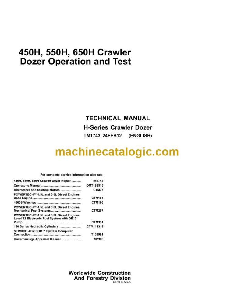
Brand: John Deere

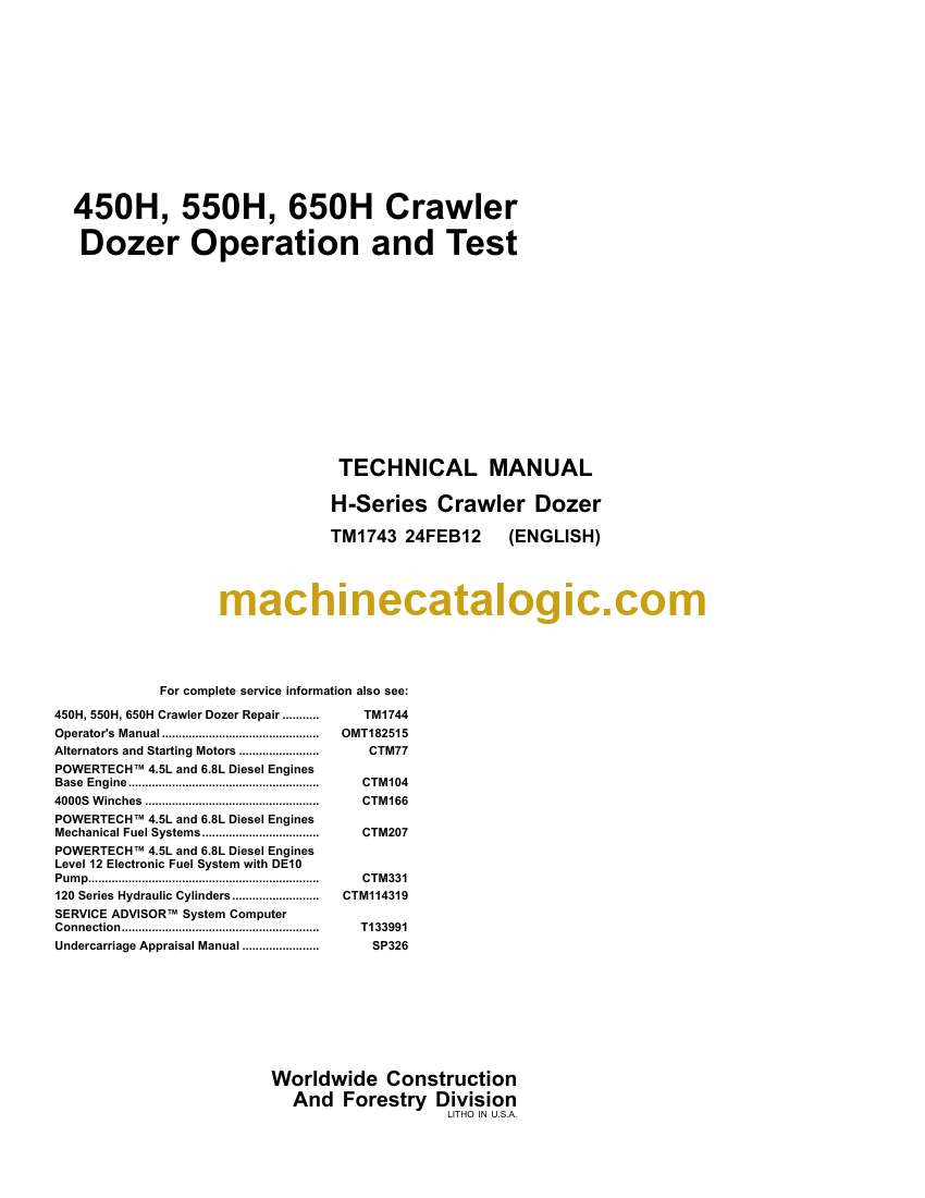
Model: 450H, 550H, 650H Crawler Dozer

Book No: TM13090X19

Type of Document: Operation and Test Technical Manual

Excellent Rating (4.8) on Trustpilot · Trusted Worldwide
Categories: ,

$ 40

Share:

John Deere 450H, 550H, 650H Crawler Dozer Operation and Test Technical Manual (TM13090X19)

John Deere 450H, 550H, 650H Crawler Dozer Operation and Test Technical Manual (TM13090X19)

John Deere 450H, 550H, 650H Crawler Dozer Index:

  • Contents
    • General Information
      • Safety
        • Recognize Safety Information
        • Follow Safety Instructions
        • Operate Only If Qualified
        • Wear Protective Equipment
        • Avoid Unauthorized Machine Modifications
        • Inspect Machine
        • Stay Clear of Moving Parts
        • Avoid High-Pressure Fluids
        • Beware of Exhaust Fumes
        • Prevent Fires
        • Prevent Battery Explosions
        • Handle Chemical Products Safely
        • Dispose of Waste Properly
        • Prepare for Emergencies
        • Add Cab Guarding For Special Uses
        • Start Only From Operator’s Seat
        • Prevent Unintended Machine Movement
        • Avoid Work Site Hazards
        • Keep Riders Off Machine
        • Avoid Backover Accidents
        • Avoid Machine Tip Over
        • Park And Prepare For Service Safely
        • Service Cooling System Safely
        • Remove Paint Before Welding or Heating
        • Make Welding Repairs Safely
        • Drive Metal Pins Safely
        • Safety Signs
        • Instrument Panel with Gauge Package—If Equipped (Earlier Machine
        • Instrument Panel Functions (Earlier Machines)
        • Instrument Panel (Later Machines)
        • Instrument Panel Functions (Later Machines)
        • Transmission Controller Display Window
        • Air Conditioning and Cab Heater—If Equipped
        • Windshield Wiper and Washer Controls
        • Windshield Washer Reservoir
        • Horn Switch
        • Auxiliary Power Outlet—If Equipped
        • Side Windows—Secondary Exits
        • Adjust Non-Suspension Seat
        • Adjust Suspension Seat—If Equipped
        • Adjust Armrest
        • Seat Belt
        • Live With Safety
      • General Specifications
        • 450H and 450H-LT Crawler Dozer Dimensions
        • 450H-LGP Crawler Dozer Dimensions
        • 450H Crawler Dozer Specifications
        • 450H Other Information
        • 450H Crawler Dozer Weights
        • 450H Crawler Dozer Drain and Refill Capacities
        • 550H Crawler Dozer Dimensions
        • 550H Crawler Dozer Specifications
        • 550H Crawler Dozer Weights
        • 550H-LGP Crawler Dozer Dimensions
        • 550H-LGP Crawler Dozer Specifications
        • 550H-LGP Crawler Dozer Weights
        • 550H and 550H-LGP Other Information
        • 550H and 550H-LGP Crawler Dozer Drain and Refill Capacities
        • 650H Crawler Dozer Dimensions
        • 650H Crawler Dozer Specifications
        • 650H Crawler Dozer Weights
        • 650H-LGP Crawler Dozer Dimensions
        • 650H-LGP Crawler Dozer Specifications
        • 650H-LGP Crawler Dozer Weights
        • 650H and 650H-LGP Other Information
        • 650H and 650H-LGP Crawler Dozer Drain and Refill Capacities
        • 4000S Winch
      • Torque Values
        • Hardware Torque Specifications
        • Keeping ROPS Installed Properly
        • Checking Track Shoe Cap Screw Torque
        • Unified Inch Bolt and Screw Torque Values
        • Metric Bolt and Screw Torque Values
        • Additional Metric Cap Screw Torque Values
        • Check Oil Lines And Fittings
        • O-Ring Groove Connections
        • Service Recommendations For Flat Face O-Ring Seal Fittings
        • Service Recommendations for O-Ring Boss Fittings
        • Service Recommendations for Inch Series Four Bolt Flange Fitting
        • Service Recommendations for Metric Series Four Bolt Flange Fitti
      • Fuels and Lubricants
        • Diesel Fuel
        • Low Sulfur Diesel Fuel Conditioner
        • Diesel Fuel Storage
        • Fuel Tank
        • Diesel Engine Oil
        • Track Rollers, Front Idler and Carrier Roller Oil
        • Transmission and Hydraulic Oil
        • Winch Oil
        • Inner and Outer Final Drive Oil
        • Grease
        • Lubricant Storage
        • Alternative and Synthetic Lubricants
        • Mixing of Lubricants
        • Heavy Duty Diesel Engine Coolant
    • Operational Checkout Procedure
      • System Operational Checks
        • Operational Checkout
        • John Deere PowerTechPowerTech is a registered trademark of Deere
        • John Deere Engine Accessories—Use CTM11
        • Alternators And Starting Motors—Use CTM77
        • Operational Checkout
          • Cooling System Checks
          • Air System Check
          • Lubrication System Checks
          • Fuel System Checks
          • Engine Speed And Performance Checks
        • Hydrostatic Transmission Operational Checks
          • Transmission Checks
        • Operational Electrical Checks
          • Battery Disconnect Switch, Key Switch, Display Monitor, Battery,
          • Indicators, Shift Lever Linkage and Reverse Warning Alarm Checks
          • Neutral Start Switch and Start Circuit Checks
          • Engine Speed Control and Decelerator Checks
          • Hydraulic System Checks
          • Undercarriage Checks
          • Accessory Checks
          • Blower/Heater/Air Conditioning Component Operational Checks
    • Engine
      • Theory Of Operation
        • POWERTECHPOWERTECH is a trademark of Deere & Company™ 4.5L (4045
        • General Engine Description
        • Cold Weather Starting Aid Operation
      • System Diagnostic Information
        • POWERTECHPOWERTECH is a trademark of Deere & Company™ 4.5L (4045
        • Make Visual Inspection Of Engine And Supporting Systems
        • Diagnose Engine Malfunctions
      • Adjustments
        • POWERTECHPOWERTECH is a trademark of Deere & Company™ 4.5L (4045
        • Accessing RPM
        • Engine Speed Adjustment (450H, 550H S.N. —910010) (650H S.N.—924
        • Slow and Fast Idle Check (450H, 550H S.N. 910011— ) (650H S.N. 9
        • Engine Speed Control Linkage Adjustment (S.N. —910010)
        • Engine Speed Control Linkage Adjustment (S.N. 910011— )
        • Injection Pump Dynamic Timing Adjustment
      • Tests
        • POWERTECHPOWERTECH is a trademark of Deere & Company™ 4.5L (4045
        • Fuel System Test
        • Turbocharger Boost Pressure Test
    • Electrical System
      • System Information
        • Electrical Diagram Information
      • System Diagrams
        • Explanation Of Wire Markings
        • Fuse Specifications For Cab (S.N. —910010)
        • Fuse Specifications For Cab (S.N. 910011— )
        • Fuse Specifications For ROPS (S.N. —910010)
        • Fuse Specifications For ROPS (S.N. 910011— )
        • Component Identification Table
        • System Functional Schematic, Wiring Diagram And Component Locati
        • System Functional Schematic Section Legend (S.N. —883588)
        • System Functional Schematic (S.N —883588) —1 Of 15
        • System Functional Schematic—Continued 2 Of 15
        • System Functional Schematic—Continued 3 Of 15
        • System Functional Schematic—Continued 4 Of 15
        • System Functional Schematic—Continued 5 OF 15
        • System Functional Schematic—Continued 6 Of 15
        • System Functional Schematic—Continued 7 Of 15
        • System Functional Schematic—Continued 8 Of 15
        • System Functional Schematic—Continued 9 Of 15
        • System Functional Schematic—Continued 10 Of 15
        • System Functional Schematic—Continued 11 Of 15
        • System Functional Schematic—Continued 12 Of 15
        • System Functional Schematic—Continued 13 Of 15
        • System Functional Schematic—Continued 14 Of 15
        • System Functional Schematic—Continued 15 Of 15
        • System Functional Schematic, Wiring Diagram And Component Locati
        • System Functional Schematic Section Legend (S.N. 883589— 910010)
        • System Functional Schematic (S.N. 583889—910010 ) With (SIG) Spe
        • System Functional Schematic—Continued 2 Of 16
        • System Functional Schematic—Continued 3 Of 16
        • System Functional Schematic—Continued 4 Of 16
        • System Functional Schematic—Continued 5 OF 16
        • System Functional Schematic—Continued 6 Of 16
        • System Functional Schematic—Continued 7 Of 16
        • System Functional Schematic—Continued 8 Of 16
        • System Functional Schematic—Continued 9 Of 16
        • System Functional Schematic—Continued 10 Of 16
        • System Functional Schematic—Continued 11 Of 16
        • System Functional Schematic—Continued 12 Of 16
        • System Functional Schematic—Continued 13 Of 16
        • System Functional Schematic—Continued 14 Of 16
        • System Functional Schematic—Continued 15 Of 16
        • System Functional Schematic—Continued 16 Of 16
        • System Functional Schematic, Wiring Diagram And Component Locati
        • System Functional Schematic Section Legend (450H, 550H S.N. 9100
        • System Functional Schematic (450H, 550H S.N. 910011— ) (650H S.N
        • System Functional Schematic, Wiring Diagram And Component Locati
        • System Functional Schematic Section Legend (650H S.N. 910011—924
        • System Functional Schematic (650H S.N. 910011—924717)
        • Cab Harness (W5) Wiring Diagram 1 Of 8 (S.N. —883588)
        • Cab Harness (W5) Wiring Diagram 1 Of 8 (S.N. 883589— 910010)
        • Cab Harness (W5) Wiring Diagram—Continued 2 Of 8 (S.N. —910010)
        • Cab Harness (W5) Wiring Diagram 3 Of 8 (S.N. —910010)
        • Cab Harness (W5) Wiring Diagram 4 Of 8 (S.N. —910010)
        • Cab Harness (W5) Wiring Diagram 5 Of 8 (S.N. —910010)
        • Cab Harness (W5) Wiring Diagram 6 Of 8 (S.N. —910010)
        • Cab Harness (W5) Wiring Diagram 7 Of 8 (S.N. —910010)
        • Cab Harness (W5) Wiring Diagram 8 Of 8 (S.N. —910010)
        • Cab Harness (W5) Wiring Diagram (450H, 550H S.N. 910011— )
        • Cab Harness (W5) Wiring Diagram (650H S.N. 910011— )
        • Cab Harness (W5) Component Location (S.N. —910010) 1 Of 8
        • Cab Harness (W5) Component Location (S.N. 910011— ) 1 Of 8
        • Cab Harness (W5) Component Location (S.N. —883588) 2 Of 8
        • Cab Harness (W5) Component Location (S.N. 883589—910010) 2 Of 8
        • Cab Harness (W5) Component Location (S.N. 910011— ) 2 Of 8
        • Cab Harness (W5) Component Location 3 Of 8
        • Cab Harness (W5) Component Location 4 Of 8
        • Cab Harness (W5) Component Location (S.N. —883588) 5 Of 8
        • Cab Harness (W5) Component Location (450H, 550H S.N. 583589—9100
        • Cab Harness (W5) Component Location (450H, 550H S.N. 910011— ) 5
        • Cab Harness (W5) Component Location (S.N. —883588) 6 Of 8
        • Cab Harness (W5) Component Location (S.N. 883589—910010) 6 Of 8
        • Cab Harness (W5) Component Location (S.N. 910011— ) 6 Of 8
        • Cab Harness (W5) Component Location 7 Of 8
        • Cab Harness (W5) Component Location (S.N. —883588) 8 Of 8
        • Cab Harness (W5) Component Location (S.N. 883589— ) 8 Of 8
        • Engine Harness (W6) Wiring Diagram—1 Of 2 (S.N. —910010)
        • Engine Harness (W6) Wiring Diagram—Continued 2 Of 2 (S.N. —91001
        • Engine Harness (W6) Wiring Diagram (450H, 550H S.N. 910011— ) (6
        • Engine Harness (W6) Wiring Diagram (650H S.N. 910011—924717)
        • Engine Harness (W6) Component Location 1 Of 4 (S.N. —910010)
        • Engine Harness (W6) Component Location 1 Of 4 (450H, 550H S.N. 9
        • Engine Harness (W6) Component Location 2 Of 4 (S.N. —910010)
        • Engine Harness (W6) Component Location 2 Of 4 (450H, 550H S.N. 9
        • Engine Harness (W6) Component Location 3 Of 4 (S.N. —883588)
        • Engine Harness (W6) Component Location 3 Of 4 (S.N. 883589—91001
        • Engine Harness (W6) Component Location 3 Of 4 (450H, 550H S.N. 9
        • Engine Harness (W6) Component Location 4 Of 4 (S.N. —910010)
        • Engine Harness (W6) Component Location 4 Of 4 (450H, 550H S.N. 9
        • Transmission Harness (W7) Wiring Diagram 1 Of 4 (S.N. —910010)
        • Transmission Harness (W7) Wiring Diagram 2 Of 4 (S.N. —910010)
        • Transmission Harness (W7) Wiring Diagram 3 Of 4 (S.N. —910010)
        • Transmission Harness (W7) Wiring Diagram 4 Of 4 (S.N. —910010)
        • Transmission Harness (W7) Wiring Diagram (450H, 550H S.N. 910011
        • Transmission Harness (W7) Wiring Diagram (650H S.N. 910011—92471
        • Transmission Harness (W7) Component Location 1 Of 5 (S.N. —91001
        • Transmission Harness (W7) Component Location 1 Of 5 (S.N. 910011
        • Transmission Harness (W7) Component Location 2 Of 5 (S.N. —88358
        • Transmission Harness (W7) Component Location 2 Of 5 (450H, 550H
        • Transmission Harness (W7) Component Location 2 Of 5 (450H, 550H
        • Transmission Harness (W7) Component Location 3 Of 5 (S.N. —91001
        • Transmission Harness (W7) Component Location 3 Of 5 (S.N. 910011
        • Transmission Harness (W7) Component Location 4 Of 5 (S.N. —88358
        • Transmission Harness (W7) Component Location 4 Of 5 (450H, 550H
        • Transmission Harness (W7) Component Location 4 Of 5 (450H, 550H
        • Transmission Harness (W7) Component Location 5 Of 5
        • Radio Harness (W9) Wiring Diagram
        • Radio Harness (W9) Component Location
        • Rear Wiper Harness (W11) Wiring Diagram
      • Sub-System Diagnostics
        • Power Circuit Operational Information
        • Power Circuit Theory Of Operation
        • Power Circuit Schematic
        • Power Circuit Diagnostic Procedures
          • Power Circuit Diagnostic Procedures
        • Start Circuit Operational Information
        • Start Circuit Theory Of Operation
        • Start Circuit Schematic
        • Start Circuit Diagnostic Procedures
          • Start Circuit Diagnostic Procedures
        • Charging Circuit Operational Information
        • Charging Circuit Theory Of Operation
        • Charging Circuit Schematic
        • Charging Circuit Diagnostic Procedures
          • Charging Circuit Diagnostic Procedures
        • Display Monitor, Indicator And Gauge Specifications (S.N —910010
        • Display Monitor, Indicator And Gauge Specifications (S.N. 910011
        • Display Monitor, Indicator And Gauge Circuit Operational Informa
        • Display Monitor, Indicator And Gauge Circuit Theory Of Operation
        • Display Monitor, Indicator And Gauge Circuit Schematic (S.N. —91
        • Display Monitor/Indicator Circuit Operational Information And Ci
        • Display Monitor, Indicator And Gauge Circuit Diagnostic Procedur
          • Display Monitor, Gauge Senders, And Switch Inputs Circuit Diagno
        • Engine Controller Operational Information, Theory of Operation,
        • Transmission Control Circuit Operational Information
        • Transmission Control Circuit Theory Of Operation
        • Transmission Control Circuit Schematic (S.N. —883588)
        • Transmission Control Circuit Schematic (S.N. 883589—910010) With
        • Transmission Control Circuit Schematic (S.N. 910011— ) With (SIG
        • Transmission Control Circuit (Flow Chart)
        • Transmission Controller Circuit Diagnostic Procedures
        • Transmission Controller Test
        • Decelerator Sensor (B1) Circuit Test (S.N. —910010)
        • Decelerator Sensor (B1) Circuit Test (S.N. 910011— )
        • Transmission Speed Control Sensor (B4) Circuit Test
        • Transmission Speed Control Switch (B4) Circuit Test With Speed I
        • Reverse Speed Ratio Switch (B27) Circuit Test With Speed In Grip
        • Reverse Speed Ratio Switch (B27) Switch Test With Speed In Grip
        • Left And Right Steer Sensor (B5) Circuit Test
        • FNR Sensor (B2) And Neutral Start Switch (S3) Circuit Test
        • Motor Shift Solenoid (Y3) Circuit Test (RH)
        • Motor Shift Solenoid (Y4) Circuit Test (LH)
        • Hydrostatic Pump Speed Sensor B6 Circuit Test
        • Left Track Motor Speed Sensor B7 Circuit Test
        • Right Track Motor Speed Sensor B3 Circuit Test
        • Rear Pump (LH) Pressure Control Pilot (PCP) B8 Circuit Test
        • Front Pump (RH) Pressure Control Pilot (PCP) B9 Circuit Test
        • Wiper And Washer Circuit Operational Information
        • Wiper And Washer Circuit Theory Of Operation
        • Wiper And Washer Circuit Schematic
        • Wiper And Washer Circuit Diagnostic Procedures
          • Wiper And Washer Circuit Diagnostic Procedures
        • Heater Blower Circuit Operational Information
        • Heater Blower Circuit Theory Of Operation
        • Heater Blower Circuit Schematic
        • Heater Blower Circuit Diagnostic Procedures
          • Heater Blower Circuit Diagnostic Procedures
        • Under Seat Heater Circuit Operational Information
        • Under Seat Heater Circuit Theory Of Operation
        • Under Seat Heater Circuit Schematic
        • Under Seat Heater Circuit Diagnostic Procedures
          • Under Seat Heater Circuit Diagnostic Procedures
        • Front And Rear Light Circuit Operational Information
        • Front And Rear Light Circuit Theory Of Operation
        • Front And Rear Light Circuit Schematic
        • Front And Rear Light Circuit Diagnostic Procedures
          • Front And Rear Light Circuit Diagnostic Procedures
        • Radio Circuit Operational Information
        • Radio Circuit Theory Of Operation
        • Radio Circuit Schematic
        • Radio Circuit Diagnostic Procedures
          • Radio Circuit Diagnostic Procedures
      • References
        • Alternators And Starting Motors—Use CTM77
        • Service Equipment And Tools
        • Battery Specifications
        • Battery Operation
        • Diagnose Battery Malfunctions
        • Check Battery Electrolyte Level And Terminals
        • Procedure For Testing Batteries
        • Using Booster Batteries—12 Volt System
        • Alternator Operation—65 Amp And 95 Amp Bosch Alternator
        • Alternator Operation—65 Amp And 95 Amp Bosch Alternator
        • Starter Operation
        • Transmission Controller Display Window Structure
        • Transmission Controller Display Window Structure (Single Lever C
        • Transmission Controller Display Window Structure (Single Lever C
        • Accessing And Clearing Stored Transmission Controller Diagnostic
        • Accessing RPM
        • Calibrate Transmission Controller (With Single Lever Control) (S
        • Calibrate Transmission Controller (With Single Lever Control) (S
        • Calibrate Transmission Controller (With Single Lever Control) (S
        • Calibrate Transmission Controller (With Single Lever Control And
        • Calibrate Transmission Controller (With Single Lever Control And
        • Calibrate Transmission Controller (With Single Lever Control And
        • Accessing Transmission Controller Rate Of Speed (With Single Lev
        • Accessing Transmission Controller Rate Of Speed (With Single Lev
        • Accessing Transmission Controller Rate Of Speed (With Single Lev
        • Accessing Transmission Controller Rate Of Speed (With Single Lev
        • Accessing Transmission Controller Diagnostics (With Single Lever
        • Accessing Transmission Controller Diagnostics (With Single Lever
        • Accessing Transmission Controller Diagnostics (With Single Lever
        • Accessing Transmission Controller Diagnostics (With Single Lever
        • Calculations For Diagnostic Transmission Calibration Limits For
        • Diagnostic Transmission Calibration Limits Table
        • Transmission Controller Diagnostic Trouble Codes And Calibration
          • !CAL Displayed On Controller and Check Diagnostic Trouble Code L
          • F311 Transmission Shutdown (Diagnostic Trouble Code)
          • F314 Transmission Shutdown (Diagnostic Trouble Code)
          • F321 Transmission Shutdown (Diagnostic Trouble Code)
          • F324 Transmission Shutdown (Diagnostic Trouble Code)
          • F330 Transmission Shutdown (Diagnostic Trouble Code) FNR Sensor
          • F331 Transmission Shutdown (Diagnostic Trouble Code) FNR Sensor
          • F334 Transmission Shutdown (Diagnostic Trouble Code) FNR Sensor
          • F335 Transmission Shutdown (Diagnostic Trouble Code) FNR Sensor
          • F336 Transmission Shutdown (Calibration Code) FNR Sensor (B2)
          • F337 Transmission Shutdown (Calibration Code) FNR Sensor (B2)
          • F338 Transmission Shutdown (Calibration Code) FNR Sensor (B2)
          • F339 Transmission Shutdown (Calibration Code) FNR Sensor (B2)
          • F340 No Steer (3.25 mph) (Diagnostic Trouble Code) Left and Righ
          • F341 No Steer (3.25 mph) (Diagnostic Trouble Code) Left and Righ
          • F344 No Steer (3.25 mph) (Diagnostic Trouble Code) Left and Righ
          • F345 No Steer (3.25 mph) (Diagnostic Trouble Code) Left and Righ
          • F346 No Steer (3.25 mph) (Calibration Code) Left and Right Steer
          • F347 No Steer (3.25 mph) (Calibration Code) Left and Right Steer
          • F348 No Steer (3.25 mph) (Calibration Code) Left and Right Steer
          • F349 No Steer (3.25 mph) (Calibration Code) Left and Right Steer
          • F350 No Anti-Stall (3.25 mph) (Diagnostic Trouble Code) Decelera
          • F351 No Anti-Stall (3.25 mph) (Diagnostic Trouble Code) Decelera
          • F353 (B1) Decelerator Sensor (S.N. 910011— )
          • F354 No Anti-Stall (3.25 mph) (Diagnostic Trouble Code) Decelera
          • F355 No Anti-Stall (3.25 mph) (Diagnostic Trouble Code) Decelera
          • F355 (B1) Decelerator Sensor (S.N. 910011— )
          • F356 No Anti-Stall (3.25 mph) (Calibration Code) Decelerator Sen
          • F357 No Anti-Stall (3.25 mph) (Calibration Code) Decelerator Sen
          • F358 No Anti-Stall (3.25 mph) (Calibration Code) Decelerator Sen
          • F359 No Anti-Stall (3.25 mph) (Calibration Code) Decelerator Sen
          • F360 (3.25 mph) (Diagnostic Trouble Code) Transmission Speed Con
          • F361 (3.25 mph) (Diagnostic Trouble Code) Transmission Speed Con
          • F364 (3.25 mph) (Diagnostic Trouble Code) Transmission Speed Con
          • F365 (3.25 mph) (Diagnostic Trouble Code) Transmission Speed Con
          • F366 No Anti-Stall (3.25 mph) (Calibration Code) Transmission Sp
          • F367 No Anti-Stall (3.25 mph) (Calibration Code) Transmission Sp
          • F368 No Anti-Stall (3.25 mph) (Calibration Code) Transmission Sp
          • F369 No Anti-Stall (3.25 mph) (Calibration Code) Transmission Sp
          • F370 Possible Mistracking (Diagnostic Trouble Code) Left Track M
          • F372 Possible Mistracking (Diagnostic Trouble Code) Left Track M
          • F373 Possible Mistracking (Diagnostic Trouble Code) Left Track M
          • F375 Possible Mistracking (Diagnostic Trouble Code) Left Track M
          • F380 Possible Mistracking (Diagnostic Trouble Code) Right Track
          • F382 Possible Mistracking (Diagnostic Trouble Code) Right Track
          • F383 Possible Mistracking (Diagnostic Trouble Code) Right Track
          • F385 Possible Mistracking (Diagnostic Trouble Code) Right Track
          • F390 No Antistall (Diagnostic Trouble Code) Hydrostatic Pump Spe
          • F392 No Antistall (Diagnostic Trouble Code) Hydrostatic Pump Spe
          • F393 No Antistall (Diagnostic Trouble Code) Hydrostatic Pump Spe
          • F393 (B6) Crank Position Sensor—450H, 550H (S.N. 910011— ); 650H
          • F395 No Antistall (Diagnostic Trouble Code) Hydrostatic Pump Spe
          • F395 (B6) Crank Position Sensor—450H, 550H (S.N. 910011— ); 650H
          • F396 No Antistall (Calibration Code) Hydrostatic Pump Speed Sens
          • F397 Transmission Shutdown (Calibration Code) Hydrostatic Pump S
          • F398 Transmission Shutdown (Calibration Code) Hydrostatic Pump S
          • F399 No Antistall (Calibration Code) Hydrostatic Pump Speed Sens
          • F3A0 No Forward Direction (Diagnostic Trouble Code) Rear (LH) Pu
          • F3A5 Transmission Shutdown (Diagnostic Trouble Code) Rear (LH) P
          • F3A6 No Forward Motion (Calibration Code) Rear (LH) PCP (B8)
          • F3A7 No Forward Motion (Calibration Code) Rear (LH) PCP (B8)/Lef
          • F3A8 (3.25 mph) (Calibration Code) Rear (LH) PCP (B8)
          • F3A9 (3.25 mph) (Calibration Code) Rear (LH) PCP (B8)
          • F3C0 No Forward Direction (Diagnostic Trouble Code) Front (RH) P
          • F3C5 Transmission Shutdown (Diagnostic Trouble Code) Front (RH)
          • F3C6 No Forward Motion (Calibration Code) Front (RH) PCP (B9)
          • F3C7 No Forward Motion (Calibration Code) Front (RH) PCP (B9)/Ri
          • F3C8 (3.25 mph) (Calibration Code) Front (RH) PCP (B9)
          • F3C9 (3.25 mph) (Calibration Code) Front (RH) PCP (B9)
          • F3D0 No Reverse Direction (Diagnostic Trouble Code) Front (RH) P
          • F3D5 Transmission Shutdown (Diagnostic Trouble Code) Front (RH)
          • F3D6 No Reverse Motion (Calibration Code) Front (RH) PCP (B9)
          • F3D7 No Reverse Motion (Calibration Code) Front (RH) PCP (B9)/Ri
          • F3D8 (3.25 mph) (Calibration Code) Front (RH) PCP (B9)
          • F3D9 (3.25 mph) (Calibration Code) Front (RH) PCP (B9)
          • F3E0 No Reverse Direction (Diagnostic Trouble Code) Rear (LH) Pu
          • F3E5 Transmission Shutdown (Diagnostic Trouble Code) Rear (LH) P
          • F3E6 No Reverse Motion (Calibration Code) Rear (LH) PCP (B8)
          • F3E7 No Reverse Motion (Calibration Code) Rear (LH) PCP (B8)/Lef
          • F3E8 (3.25 mph) (Calibration Code) Rear (LH) PCP (B8)
          • F3E9 (3.25 mph) (Calibration Code) Rear (LH) PCP (B8)
          • F3H1 Transmission Shutdown (Diagnostic Trouble Code) Neutral Sta
          • F3H4 Transmission Shutdown (Diagnostic Trouble Code) Neutral Sta
          • F3H6 Transmission Shutdown (Calibration Code) Neutral Start Swit
          • F3H7 Transmission Shutdown (Calibration Code) Neutral Start Swit
          • F3H8 Transmission Shutdown (Calibration Code) Neutral Start Swit
          • F3H9 Transmission Shutdown (Calibration Code) Neutral Start Swit
          • F3J0 (3.25 mph) (Diagnostic Trouble Code) Open In ID Plug
          • F3J1 (3.25 mph) (Diagnostic Trouble Code) Transmission Harness (
          • F3J4 (3.25 mph) (Diagnostic Trouble Code) Transmission Harness (
          • F3J5 (3.25 mph) (Diagnostic Trouble Code) Transmission Harness (
          • F3K3 (3.25 mph) (Diagnostic Trouble Code) (RH) Motor Shift Solen
          • F3L3 (3.25 mph) (Diagnostic Trouble Code) (LH) Motor Shift Solen
          • F3M1 Possible Mistracking (Diagnostic Trouble Code) Left Track M
          • F3M4 Possible Mistracking (Diagnostic Trouble Code) Left Track M
          • F3N1 Possible Mistracking (Diagnostic Trouble Code) Right Track
          • F3N4 Possible Mistracking (Diagnostic Trouble Code) Right Track
          • F3P0 Return FNR To Neutral (Diagnostic Trouble Code) Park Lock L
          • F3P5 Return FNR To Neutral (Diagnostic Trouble Code) Park Lock L
          • F3R0 Reverse Speed Ratio to 115% (Diagnostic Trouble Code) Rever
          • F3R1 Return to 115% Reverse Speed (Diagnostic Trouble Code) Tran
          • F3R4 Return to 115% Reverse Speed (Diagnostic Trouble Code) Tran
          • F3R5 Reverse Speed Ratio to 115% (Diagnostic Trouble Code) Rever
          • F3T0 (3.25 mph) (Diagnostic Trouble Code) Speed In Grip (B4)
          • F3T1 (3.25 mph) (Diagnostic Trouble Code) Speed In Grip (B4)
          • F3T4 (3.25 mph) (Diagnostic Trouble Code) Speed In Grip (B4)
          • F3T5 (3.25 mph) (Diagnostic Trouble Code) Speed In Grip (B4)
          • F3T6 (3.25 mph) (Calibration Code) Speed In Grip (B4)
          • F3T7 (3.25 mph) (Calibration Code) Speed In Grip (B4)
          • F3T8 (3.25 mph) (Calibration Code) Speed In Grip (B4)
          • F3T9 (3.25 mph) (Calibration Code) Speed In Grip (B4)
        • Engine Diagnostic Trouble Codes (450H, 550H S.N. 910011— ) (650H
        • Display Monitor Diagnostic Trouble Codes (450H, 550H S.N. 910011
        • Access Display Monitor And Engine Diagnostic Trouble Codes (S.N.
        • Program Display Monitor (S.N. 910011— )
        • Setting Transmission Controller To Default Values
        • Machine Identity Plugs (S.N. 883589— ) For Standard Single Lever
        • Test Harness Kit (JT07329)
        • Test Harness Kit-Continued
        • Transmission Controller Connectors
        • Test Box (JT07349) For Transmission Controller And Transmission
        • Test Box (JT07349)-Continued
        • Rotary Sensor Component Location (Single Lever Steer)
        • Rotary Sensor Component Location With (SIG) Speed In Grip Option
    • Hydraulic System
      • Theory of Operation
        • Dozer Hydraulic System Operation
        • Component Location—Dozer
        • Hydraulic System Schematic (SN —902404)
        • Hydraulic System Schematic (SN 902405—)
        • Lift Cylinders Circuit-Blade Raise Position
        • Blade Angle Cylinder Circuit W/O Circuit Reliefs (SN —902404)
        • Blade Angle Cylinder Circuit With Circuit Reliefs (SN 902405—)
        • Blade Tilt Cylinder Circuit—Tilt Left Position
        • Hydraulic Pump
        • Hydraulic Pump and Reservoir Operation
        • Hydraulic Filter Operation—Normal
        • Hydraulic Filter Operation Continued—Restricted
        • Hydraulic Control Valve Operation
        • Hydraulic System And Angle Circuit Relief Valve Operation
        • Control Valve Inlet Section Operation
        • Dozer Blade Auxiliary Valve Operation—Neutral Position
        • Dozer Blade Lift Valve Operation—Lift Position
        • Dozer Blade Angle Valve Operation-Right Angle Position (SN —9024
        • Dozer Blade Angle Valve Operation-Right Angle Position (SN 90240
        • Dozer Blade Tilt Valve Operation—Tilt Right Position
        • Control Valve Outlet Cover
        • Hydraulic Cylinder Operation
      • Diagnostic Information
        • Use These Seven Basic Steps to Diagnose and Test the Hydraulic S
        • Make a Pretest Inspection and an Operation Check of the Machine
        • Hydraulic System Pretest
        • Diagnose Hydraulic System
      • Adjustments
        • T—Bar Linkage Adjustment
        • Auxiliary Lever Linkage Adjustment
      • Tests
        • Fluid Sampling Procedure—If Equipped
        • JT02156A Digital Pressure and Temperature Analyzer Kit Installat
        • JT05801 Clamp—On Electronic Tachometer Installation
        • Hydraulic Oil Warm-Up Procedure
        • Hydraulic Pump Flow Test
        • Hydraulic System Relief Valve Test
        • Angle Circuit Relief Valve Test—With Remote Pump (SN 902405—)
        • Pump General Performance Test Using Cycle Times
        • Hydraulic Cylinder Drift Test Procedure
        • Lift Cylinder Drift Test
        • Cylinder Leakage Test
        • Hydraulic Oil Clean-Up Procedure Using Portable Filter Caddy
    • Hydrostatic System
      • Theory of Operation
        • Hydrostatic System
        • Transmission Control Circuit—Flow Chart
        • Charge Pump
        • Hydrostatic Filter
        • Neutral Charge Relief Valve
        • Park Brake Valve
        • Multi-Function Valve
        • Oil Cooler Bypass Valve
        • Pump Pressure Control Pilot (PCP)
        • Pump Displacement Control Valve (PDCV)
        • Hydrostatic Pump
        • Flushing Valve and Operating Charge Relief Valve
        • Hydrostatic Motor Operation
        • Hydrostatic System Component Location
        • Hydrostatic System Diagram—Park Brake On (Neutral) (S.N. —908551
        • Hydrostatic System Diagram—Park Brake On (Neutral) (S.N. 908552—
        • Hydrostatic System Diagram—Reverse (Low Speed) (S.N. —908551)
        • Hydrostatic System Diagram—Reverse (Low Speed) (S.N. 908552— )
        • Hydrostatic System Diagram—Forward (High Speed) (S.N. —908551)
        • Hydrostatic System Diagram—Forward (High Speed) (S.N. 908552— )
        • Hydrostatic Schematic—Neutral (Park Brake On)
      • Diagnostic Information
        • Overheating – Flow Chart
        • Low Charge Pressure – Flow Chart
        • Mistrack/Indexes – Flow Chart
        • Machine Will Not Reach Full Speed – Flow Chart
        • Low Power – Flow Chart
        • Engine Starts But Both Tracks Do Not Move or Stop Moving – Flow
        • Moves Only One Direction or One Track Won’t Move – Flow Chart
        • Controller Won’t Calibrate And One Of The Following Codes Are Di
      • Adjustments
        • Brake Pedal to Brake Valve Linkage Adjustment
        • Park Lock Linkage Adjustment
        • Hydrostatic Motor Speed Sensor Adjustment
        • Hydrostatic Pump Speed Sensor Adjustment (450H, 550H S.N. —91001
        • Pressure Control Pilot (PCP) Internal Adjustment
        • Pump Displacement Control Valve (PDCV) Neutral (Null) Adjustment
        • Single Lever Control (SLC) Adjustment
      • Test
        • JT05800 Digital Thermometer Installation
        • Transmission Oil Warm-Up Procedure
        • Releasing the Park Brake to Tow the Machine
        • Disconnect Park Brake for Diagnostic Test
        • Hydrostatic Pump and Motor Initial Start-Up Procedure
        • Hydrostatic Pump Flushing Procedure
        • Pressure Control Pilot (PCP) Manual Override Test
        • Pressure Control Pilot (PCP) Test
        • Multi-Function Relief Valve Test
        • Transmission Efficiency Test
        • Neutral Charge Relief Pressure Test
        • Operating Charge Relief Pressure Test
        • Pump Servo Pressure Test
        • Hydrostatic Motor Min./Max. Angle Control Piston Pressure Test
        • Hydrostatic Motor Min./Max. Angle Stop Adjustment (S.N. —899548)
        • Hydrostatic Motor Min./Max. Angle Stop Adjustment (S.N. 899549—
        • Charge Pump Flow Test
        • Cooler Bypass Valve Test
    • Heating and Air Conditioning
      • Theory of Operation
        • Proper Refrigerant Handling
        • R134a Refrigerant—Cautions
        • R134a Refrigerant Theory Of Operation
        • Air Conditioning Circuit Specifications
        • Air Conditioning Circuit Operational Information
        • Air Conditioning Circuit Theory Of Operation
        • Air Conditioning Circuit Schematic
        • Air Conditioning (W8) Wiring Diagram
        • Heater Blower Circuit Operational Information
        • Heater Blower Circuit Theory Of Operation
        • Heater Blower Circuit Schematic
        • Receiver/Dryer—Theory Of Operation
        • Expansion Valve —Theory Of Operation
        • Relief Valve Compressor—Theory Of Operation
        • Temperature Control—Theory Of Operation
        • Freeze Control Switch Operation
      • Diagnostic Information
        • Diagnose Air Conditioning Electrical Malfunctions
        • Air Conditioning Component Location
      • Adjustments
        • Special or Essential Tools
        • Service Equipment and Tools
        • Other Materials
        • Specifications
        • Proper Refrigerant Handling
        • R134a Refrigerant—Cautions
        • R134a Compressor Oil Charge Check
        • R134a Compressor Oil Removal
        • R134a Component Oil Charge
        • R134a Refrigerant Recovery, Recycling and Charging Station Insta
        • Recover R134a System
        • Evacuate R134a System
        • Charge R134a System
        • R134a System Cleaning Procedure
        • R134a System—Purge
        • Flush Air Conditioner System
      • Test
        • Special or Essential Tools
        • Service Equipment and Tools
        • Specifications
        • Proper Refrigerant Handling
        • R12 And R134a Refrigerant Cautions
        • Diagnostic Chart Pressure
        • Expansion Valve Operating Test
        • Blower Switch Test
        • Blower Resistor Test
        • Heater Blower Motor Test (Upper Cab)
        • Freeze Control Switch Test
        • Air Conditioning Switch Test
        • Air Conditioner Low Pressure Switch Check
        • Air Conditioner Low Pressure Switch Test
        • Air Conditioner High Pressure Switch Check
        • Air Conditioner High Pressure Switch Test
        • Air Conditioning Compressor Clutch Coil Test
        • Freeze Control Switch Test
        • Air Conditioning System—Test Leak
        • Refrigerant Hoses And Tubing Inspection
  • Page Number
    • Section 9000
      • Group 01
      • Group 02
      • Group 03
      • Group 04
    • Section 9005
      • Group 10
    • Section 9010
      • Group 05
      • Group 15
      • Group 20
      • Group 25
    • Section 9015
      • Group 05
      • Group 10
      • Group 15
      • Group 20
    • Section 9025
      • Group 05
      • Group 15
      • Group 20
      • Group 25
    • Section 9026
      • Group 05
      • Group 15
      • Group 20
      • Group 25
    • Section 9031
      • Group 05
      • Group 15
      • Group 20
      • Group 25

John Deere

Latest Product

0
    0
    Your Cart
    Your cart is emptyReturn to Shop