The Liebherr MK 140 Mobile Construction Crane spends its life on tight sites, doing fast setup and teardown where downtime really hurts. When something electrical or hydraulic acts up, the first guy reaching for a BMK is usually the tech trying to match a fault or schematic symbol to a real-world box, plug, or valve. Component identification is what keeps you from tearing half the crane apart just to find one relay or sensor buried in the superstructure. This Technical Information & BMK Components Manual for SN 077511 is built exactly for that job, not for step‑by‑step repairs.
What this manual helps you do
- Identify where specific components sit on the MK 140 carrier and superstructure using outline and layout diagrams.
- Locate items like “K15” or “X45” on the actual crane when you only have the reference from a wiring or hydraulic schematic.
- Trace harnesses and component groups visually so you know which panels, covers, or walkways to open before you start work.
- Cross-reference Liebherr component IDs to other factory documents like wiring diagrams or technical fault info.
- Pinpoint what Liebherr calls a given sensor, relay, valve, or connector so you can talk the same language as the parts desk or service rep.
Who this is for
This is aimed at workshop technicians, field service techs, electrical diagnostic engineers, fleet mechanics, and training instructors who need clear component locations. If you’re after repair procedures, torque specs, or part numbers, you actually want a service manual or a parts catalogue instead.
FAQ
Q: Are the diagrams clear and searchable in PDF form?
A: These BMK PDFs are usually clean scans or originals with legible component callouts and can be searched by text where the source allows.
Q: Does it cover both the carrier and the upper crane body?
A: Yes, this BMK combines carrier and superstructure component identification for the MK 140 into one product.
Q: Does it tie in with other Liebherr manuals I already have?
A: Yes, the BMK is meant to be used alongside wiring diagrams, hydraulic schematics, service manuals, and parts catalogues by matching the reference designators.
Bottom line: If your main need is “Where exactly is this component on my Liebherr MK 140, and what does Liebherr call it?”, this is the right manual. If you need how‑to repair steps or part numbers, this isn’t it.
📘 Show Index
Table of Contents:
Carrier — Table of Contents
- Fahrzeug:
- Ansicht von vorne, Beleuchtung und Spiegel
- Ansicht von hinten
- Ansicht von links
- Ansicht von rechts
- Fahrerhaus:
- Türen und Fenster, Innenbeleuchtung
- Lüftung und Wärmetauscher,
Scheibenwisch- und waschanlage
- Lüftung und Wärmetauscher
- Bedienelemente
- Bluetooth Basiseinheit – BTB, Bluetooth Terminal – BTT
- Mittelkonsole – Batteriekasten
- Mittelkonsole – Sicherungen
- Mittelkonsole – E / A- Module, ECUs
- Mittelkonsole – Relais
- Mittelkonsole – Relais, Lüfter, Widerstandmodul
- Mittelkonsole – Spannungswandler Relais Heizflansch
- Mittelkonsole – Diagnosestecker, NOT-HALT
- Druckluftanlage:
- Luftpresser und Lufttrockner
- Druckluftvorratsbehälter
- Druckgeber und Druckschalter
- Magnetventile Nebenverbraucher
- Scheibenbremsanlage Verschleißmelder
- Bremsbelag Überwachungsanzeige
- Antriebsaggregat
- D946 A7 -04 (Stufe IV SCR) / -03 (Power Band H)
- Motorsteuergerät
- Übersicht Einspritzseite
- Übersicht Abgasseite
- Übersicht Schwungradseite und Generator
- Übersicht Lüfterseite
- Kühlmittel
- Kraftstoff-Niederdrucksensoren
- Liebherr Daisy-Chain Diesel-Einspritzsystem
- Injektoren LCR-I S2
- Typenschilder:
- Kraftstoffpumpen
- Drehzahlsensoren
- Ölkreislauf
- Außentemperatur Dieselmotor
- Abschlusswiderstand CAN-LIDEC (ECU-CAN2)
- Abschlusswiderstand Motor-CAN (ECU-CAN2)
- Ladeluft-Sensoren und -Vorwärmung
- Abgasklappe
- Abgasturbolader mit Wastegate
- Nur Power Band H-Motoren
- Externe Abgasrückführung eAGR
- Intercooler Temperatur-Sensor
- Abgasnachbehandlung SCR
- Übersicht Abgasanlage
- Harnstoff-Tank und Tanksonde
- Pumpen-Modul und AdBlue-Leitungen
- AdBlue-Injektor und Upstream-Sensoren
- Downstream-Sensoren
- Umgebungsluft-Sensor und Abgasklappe
- Luftfilteranlage bei Motor -03 (Power Band H)
- Diesel-Kraftstoffanlage:
- Kraftstoff-Vorfiltereinheit, Tankgeber
- Automatisiertes Schaltgetriebe ZF 12 AS 2531 SO
- Kupplungs- und Getriebesteller
- Kühlanlage
- Übersicht, Kühlwasserstand
- Hydraulik
- Hydraulikpumpen Übersicht
- Temperatursensor Hydrauliköl, Hydrauliköltank
- Antriebsstrang
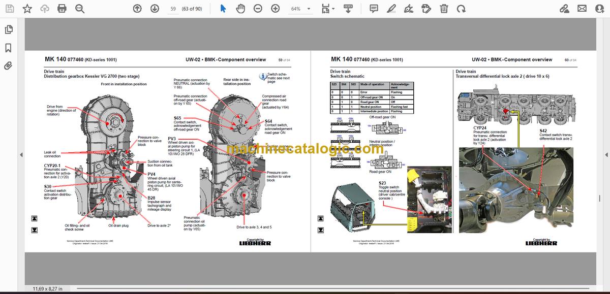
- Verteilergetriebe Kessler VG 2700 (zweistufig)
- Schaltschema
- Querdifferentialsperre Achse 2 (Antrieb 10 x 6)
- Längs- und Querdifferentialsperren
- Lenkung
- Lenkgetriebe ZF-Servocom, Ölversorgung
- Aktive Hinterachslenkung
- Steuerblock
- CAN-Ventile HAWE
- Vorspannung Zentrierung
- Winkelgeber
- Lenk- und Zentrierzylinder, Sicherheitsventile
- Abstützung
- Neigungsaufnehmer
- Abstützventile rechts – Abstützung links
- Abstützventile links- Abstützung rechts
- Schiebeholmüberwachung
- Achsfederung
- Niveaugeber
- Ventilblock – rechts
- Ventilblock – links
- Steuerventil – blockiert / gefedert
- Sonderausstattung
- Zusatzheizung Thermo PRO 90
- Klimaanlage
- Druckaufnehmer für Stützkraftanzeige*
- Batterieladegerät
- Index
Superstructure — Table of Contents
- 1 Setting the sensors
- 1.1 Setting the roller limit switch
- 1.2 Setting the plunger limit switch to be tamper-proof
- 1.3 Setting the solenoid switch
- 2 Checking the sensors
- 2.1 Checking the roller limit switch
- 2.2 Checking the plunger limit switch
- 2.3 Checking the proximity switch
- 2.4 Checking the solenoid switch
- 2.5 Checking the connector plug with bayonet lock
- 3 Switch conditions
- 4 Overview of sensors
- 4.1 Sensors on turntable and tower
- 4.2 Sensors on boom pivot section and boom centre section
- 4.3 Sensors on boom section 3 and boom section 4
- 4.4 Sensors on boom extension 1 and boom extension 2
- 4.5 Sensors according to BMK code (BXXX ascending)
- 4.6 B4 =S1 Temperature monitor
- 4.7 B4 =S12 Temperature monitor
- 4.8 B4 =S13 Temperature monitor
- 4.9 B101 Wind sensor
- 4.10 B103 Angle inclination sensor boom centre section
- 4.11 B105 Wind 2 sensor
- 4.12 B107 Steel construction temperature sensor
- 4.13 B108 Load sensor
- 4.14 B112 Basic ballast present
- 4.15 B113_1 and 113_2 Additional ballast 1 present
- 4.16 B114_1 and 114_2 Additional ballast 2 present
- 4.17 B115_1 and B115_2 Left additional ballast 3 present
- 4.18 B116_1 and B116_2 Right additional ballast 3 present
- 4.19 B117_1 Right ballasting equipment extended
- 4.20 B117_2 Left ballasting equipment extended
- 4.21 B118_1 Right ballasting equipment retracted
- 4.22 B118_2 Left ballasting equipment retracted
- 4.23 B120 Boom lower belt locked
- 4.24 B121 Boom lower belt unlocked
- 4.25 B122 Rope safety catch for boom centre section in operating position
- 4.26 B123 Rope safety catch for boom centre section in assembly position
- 4.27 B124 Boom section 4 operating position
- 4.28 B125 Boom section 4 advance shutdown operating position
- 4.29 B126 Boom section 4 transport position
- 4.30 B127 Boom section 4 advance shutdown transport position
- 4.31 B128 Rope safety catch boom section 4 operating position lower belt locked
- 4.32 B129 Rope safety catch boom section 4 assembly position lower belt unlocked
- 4.33 B130 Hoist rope pulley in trolley boom operating position
- 4.34 B131 Hoist rope pulley in jib boom operating position
- 4.35 B132 Boom tip detection 643
- 4.36 B133 Hoist rope pulley 643 in jib boom operating position
- 4.37 B134 Boom tip detection 645
- 4.38 B135 Hoist rope fixed point monitoring
- 4.39 B138 Hoist rope pulley 645 in jib boom operating position
- 4.40 B193 Cab disassembly position
- 4.41 B200 Slewing gear sensor
- 4.42 M201 Slewing gear brake 1/2 open
- 4.43 B211 Chassis turntable locked
- 4.44 B230 Wind release not active
- 4.45 B250 Trolley travel gear boom radii sensor
- 4.46 B251 Trolley travel gear disassembly position
- 4.47 M251 Trolley travel gear brake open
- 4.48 B255 Trolley rope tensioning device extended
- 4.49 B300 Lowering depth sensor
- 4.50 B307 Load hook disassembly position
- 4.51 B331 Hoist gear gear shift
- 4.52 B332 Assembly plant gear shift
- 4.53 B400 Assembly sensor
- 4.54 B412 Vertical tower
- 4.55 B413 Left tower turntable locked
- 4.56 B414 Left tower turntable unlocked
- 4.57 B415 Right tower turntable locked
- 4.58 B416 Right tower turntable unlocked
- 4.59 B417 Assembly winch slack rope
- 4.60 B418 Tower is on transport receptacle
- 4.61 B419 Left tower centre section / lower section locked
- 4.62 B420 Left tower centre section / lower section unlocked
- 4.63 B421 Right tower centre section / lower section locked
- 4.64 B422 Right tower centre section / lower section unlocked
- 4.65 B424 Tower centre section extended too far
- 4.66 B423 Tower centre section retracted
- 4.67 B425 Left tower upper section / centre section locked
- 4.68 B426 Left tower upper section / centre section unlocked
- 4.69 B427 Right tower upper section / centre section locked
- 4.70 B428 Right tower upper section / centre section unlocked
- 4.71 B429 Tower upper section retracted
- 4.72 B430 Tower upper section extended too far
- 4.73 B431 Neck guying caught
- 4.74 B432 Left boom press extended
- 4.75 B433 Left boom press retracted
- 4.76 B434 Right boom press extended
- 4.77 B435 Right boom press retracted
- 4.78 B436 Bipod in locking position
- 4.79 B437 Bipod locked
- 4.80 B438 Bipod unlocked
- 4.81 B439 Boom swung in to transport position
- 4.82 B440 Pre-centring boom upper belt locked
- 4.83 B441 Boom in transport position
- 4.84 B445 A-frame in disassembly position
- 4.85 B450 Auxiliary hoist gear sensor
- 4.86 M451 Auxiliary hoist gear brake open
- 4.87 B453 Boom pivot / centre section operating position overrun
- 4.88 B454 Boom pivot / centre section operating position
- 4.89 B500 Guy winch sensor
- 4.90 B501 Transmission temperature sensor
- 4.91 B504 Guy winch additional brake open
- 4.92 B507 Boom inclination emergency shutdown
- 4.93 B600 Overall pressure switch
- 4.94 B604 Pressure switch for tank line dynamic pressure
- 4.95 B605 Pressure switch for guy winch additional brake
- 4.96 B617 Left ballasting pressure switch
- 4.97 B618 Right ballasting pressure switch
- 4.98 B620 Pressure switch for tower turntable locking mechanism
- 4.99 B625 Pressure switch for tower centre section / lower section
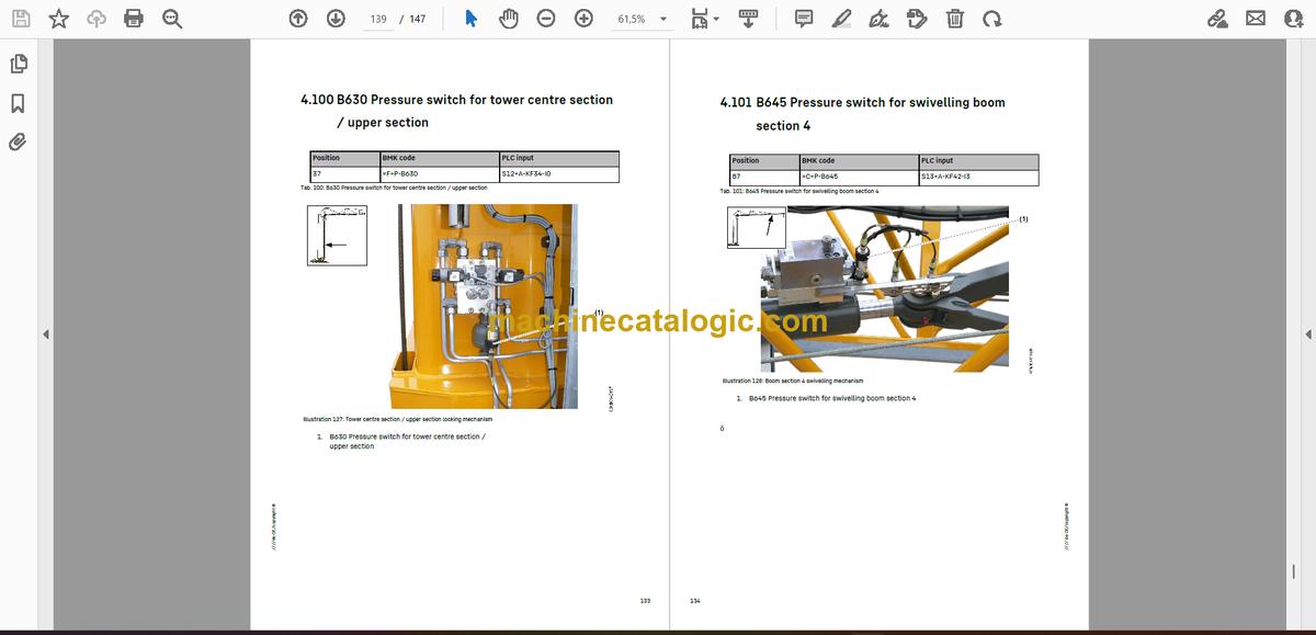
- 4.100 B630 Pressure switch for tower centre section / upper section
- 4.101 B645 Pressure switch for swivelling boom section 4
- 4.102 B653 Pressure sensor for tensioning trolley travel rope
- 4.103 B700 Cab winch value sensor
- 4.104 M711 / M712 Cab additional brake open
- 4.105 B731 Cab slack rope at the bottom
- 4.106 B732 Cab overload
- 4.107 B733 Cab rope break monitoring
Liebherr Crane


