Format: PDF (Printable Document)
File Language: English
File Pages: 216
File Size: 15.95 MB (Speed Download Link)
Brand: Kohler
Model: RXT Automatic Transfer Switches
Book No: TP-6808 1218C
Type of Document: Service and Parts Manual
$ 40
These Kohler RXT automatic transfer switches sit between utility power and the generator, usually in a basement, electrical room, or outdoor enclosure, and they decide when to move the load from street power to standby. This service and parts manual is what I keep handy when I’m tearing one down or chasing a transfer issue and need to match every relay, lug kit, and harness to the right Kohler part number. If, for example, the switch is hesitating to transfer and I find a heat-damaged contact kit, this book lets me positively ID the exact kit for that frame and control style before I place an order.
Applications & Use Cases
FAQ
Q: Can I use this manual on a tablet at the jobsite?
A: Yes, it works well digitally; you can zoom in on diagrams to read item callouts while standing at the switch.
Q: Is it worth printing sections of this manual?
A: For repetitive jobs, printing the relevant diagrams and parts pages saves time and keeps oily hands off your device.
Safety Note
Always de-energize and lock out all power sources before opening or servicing any RXT automatic transfer switch.
Safety Precautions and Instructions . . . . . . . . . . . . . . . . . . . . . . . . . . . . . . . . . . . . . . . . . . . . . . . . . . . . . . . . 7
Introduction . . . . . . . . . . . . . . . . . . . . . . . . . . . . . . . . . . . . . . . . . . . . . . . . . . . . . . . . . . . . . . . . . . . . . . . . . . . . . . 9
List of Related Materials . . . . . . . . . . . . . . . . . . . . . . . . . . . . . . . . . . . . . . . . . . . . . . . . . . . . . 10
Service Assistance . . . . . . . . . . . . . . . . . . . . . . . . . . . . . . . . . . . . . . . . . . . . . . . . . . . . . . . . . . . . . . . . . . . . . . . . 11
Section 1 Specifications and Service Views . . . . . . . . . . . . . . . . . . . . . . . . . . . . . . . . . . . . . . . . . . . . . . . . . 13
1.1 Specifications . . . . . . . . . . . . . . . . . . . . . . . . . . . . . . . . . . . . . . . . . . . . . . . . . . . . . . . . 13
1.2 Transfer Switch Components . . . . . . . . . . . . . . . . . . . . . . . . . . . . . . . . . . . . . . . . . . . 14
Section 2 Operation . . . . . . . . . . . . . . . . . . . . . . . . . . . . . . . . . . . . . . . . . . . . . . . . . . . . . . . . . . . . . . . . . . . . . . . 23
2.1 Model RXT Transfer Switch Operation . . . . . . . . . . . . . . . . . . . . . . . . . . . . . . . . . . . 23
2.2 Sources . . . . . . . . . . . . . . . . . . . . . . . . . . . . . . . . . . . . . . . . . . . . . . . . . . . . . . . . . . . . . 23
2.2.1 Terminology . . . . . . . . . . . . . . . . . . . . . . . . . . . . . . . . . . . . . . . . . . . . . . . . . . 23
2.2.2 Source Availability . . . . . . . . . . . . . . . . . . . . . . . . . . . . . . . . . . . . . . . . . . . . . 23
2.3 ATS Sequence of Operation . . . . . . . . . . . . . . . . . . . . . . . . . . . . . . . . . . . . . . . . . . . . 23
2.4 Automatic Operation Test . . . . . . . . . . . . . . . . . . . . . . . . . . . . . . . . . . . . . . . . . . . . . . 23
2.5 Time Delays . . . . . . . . . . . . . . . . . . . . . . . . . . . . . . . . . . . . . . . . . . . . . . . . . . . . . . . . . . 24
2.6 Load Control Time Delay . . . . . . . . . . . . . . . . . . . . . . . . . . . . . . . . . . . . . . . . . . . . . . . 24
2.7 Load Management Theory of Operation . . . . . . . . . . . . . . . . . . . . . . . . . . . . . . . . . . 25
2.7.1 Load Add . . . . . . . . . . . . . . . . . . . . . . . . . . . . . . . . . . . . . . . . . . . . . . . . . . . . 25
2.7.2 Load Shed . . . . . . . . . . . . . . . . . . . . . . . . . . . . . . . . . . . . . . . . . . . . . . . . . . . 26
2.7.3 Overload Shed . . . . . . . . . . . . . . . . . . . . . . . . . . . . . . . . . . . . . . . . . . . . . . . 26
2.7.4 Under Frequency Shed . . . . . . . . . . . . . . . . . . . . . . . . . . . . . . . . . . . . . . . . 26
2.7.5 Load Shed Acceleration . . . . . . . . . . . . . . . . . . . . . . . . . . . . . . . . . . . . . . . . 27
2.7.6 Changing Settings . . . . . . . . . . . . . . . . . . . . . . . . . . . . . . . . . . . . . . . . . . . . . 27
2.8 Manual Operation Check . . . . . . . . . . . . . . . . . . . . . . . . . . . . . . . . . . . . . . . . . . . . . . . 28
Section 3 Scheduled Maintenance . . . . . . . . . . . . . . . . . . . . . . . . . . . . . . . . . . . . . . . . . . . . . . . . . . . . . . . . . . 31
3.1 Introduction . . . . . . . . . . . . . . . . . . . . . . . . . . . . . . . . . . . . . . . . . . . . . . . . . . . . . . . . . . 31
3.2 Inspection and Service . . . . . . . . . . . . . . . . . . . . . . . . . . . . . . . . . . . . . . . . . . . . . . . . . 32
3.2.1 General Inspection . . . . . . . . . . . . . . . . . . . . . . . . . . . . . . . . . . . . . . . . . . . . 32
3.2.2 Internal Inspections and Maintenance . . . . . . . . . . . . . . . . . . . . . . . . . . . . 33
3.3 Testing . . . . . . . . . . . . . . . . . . . . . . . . . . . . . . . . . . . . . . . . . . . . . . . . . . . . . . . . . . . . . . 35
3.3.1 Weekly Generator Set Exercise . . . . . . . . . . . . . . . . . . . . . . . . . . . . . . . . . 35
3.3.2 Monthly Automatic Operation Test . . . . . . . . . . . . . . . . . . . . . . . . . . . . . . . 35
3.3.3 Other Tests . . . . . . . . . . . . . . . . . . . . . . . . . . . . . . . . . . . . . . . . . . . . . . . . . . . 35
3.4 Service Schedule . . . . . . . . . . . . . . . . . . . . . . . . . . . . . . . . . . . . . . . . . . . . . . . . . . . . . 37
Section 4 Troubleshooting . . . . . . . . . . . . . . . . . . . . . . . . . . . . . . . . . . . . . . . . . . . . . . . . . . . . . . . . . . . . . . . . . 39
4.1 Initial Troubleshooting . . . . . . . . . . . . . . . . . . . . . . . . . . . . . . . . . . . . . . . . . . . . . . . . . 40
4.2 Controller Settings . . . . . . . . . . . . . . . . . . . . . . . . . . . . . . . . . . . . . . . . . . . . . . . . . . . . 41
4.2.1 DC2 Controller . . . . . . . . . . . . . . . . . . . . . . . . . . . . . . . . . . . . . . . . . . . . . . . . 41
4.2.2 RDC2 Controller Menus . . . . . . . . . . . . . . . . . . . . . . . . . . . . . . . . . . . . . . . . 41
4.3 SiteTech Software . . . . . . . . . . . . . . . . . . . . . . . . . . . . . . . . . . . . . . . . . . . . . . . . . . . . . 44
4.4 RBUS Communication Troubleshooting . . . . . . . . . . . . . . . . . . . . . . . . . . . . . . . . . . 48
4.4.1 RBUS Connection Labels . . . . . . . . . . . . . . . . . . . . . . . . . . . . . . . . . . . . . . 48
4.4.2 Communication Cables . . . . . . . . . . . . . . . . . . . . . . . . . . . . . . . . . . . . . . . . 48
4.4.3 ATS Source Parameter in SiteTech . . . . . . . . . . . . . . . . . . . . . . . . . . . . . . 50
4.4.4 Number of RBUS Modules . . . . . . . . . . . . . . . . . . . . . . . . . . . . . . . . . . . . . 50
4.4.5 Communication Troubleshooting Flowcharts . . . . . . . . . . . . . . . . . . . . . . 51
4.4.6 Verify that the Controller Recognizes the RXT . . . . . . . . . . . . . . . . . . . . . 53
4.5 Faults and Notices . . . . . . . . . . . . . . . . . . . . . . . . . . . . . . . . . . . . . . . . . . . . . . . . . . . . 56
4.6 Troubleshooting Charts . . . . . . . . . . . . . . . . . . . . . . . . . . . . . . . . . . . . . . . . . . . . . . . . 57
4.7 Transfer Switch Troubleshooting . . . . . . . . . . . . . . . . . . . . . . . . . . . . . . . . . . . . . . . . 61
4.7.1 Neutral Connection . . . . . . . . . . . . . . . . . . . . . . . . . . . . . . . . . . . . . . . . . . . . 61
4.7.2 Mechanical Check . . . . . . . . . . . . . . . . . . . . . . . . . . . . . . . . . . . . . . . . . . . . 61
Table of Contents, continued
4 Table of Contents TP-6808 12/18
4.7.3 Solenoid Troubleshooting . . . . . . . . . . . . . . . . . . . . . . . . . . . . . . . . . . . . . . 61
4.8 Load Control Module (LCM) . . . . . . . . . . . . . . . . . . . . . . . . . . . . . . . . . . . . . . . . . . . . 62
4.8.1 LCM and RXT with Standard Interface Board . . . . . . . . . . . . . . . . . . . . . 62
4.8.2 LCM and RXT with Combined Interface/Load Management Board . . . 62
4.9 Load Management Troubleshooting . . . . . . . . . . . . . . . . . . . . . . . . . . . . . . . . . . . . . 64
4.9.1 Verify that Controller Recognizes Load Management Device . . . . . . . . 64
4.9.2 Load Management Troubleshooting Table . . . . . . . . . . . . . . . . . . . . . . . . 64
Section 5 Component Testing . . . . . . . . . . . . . . . . . . . . . . . . . . . . . . . . . . . . . . . . . . . . . . . . . . . . . . . . . . . . . . 67
5.1 Interface Boards . . . . . . . . . . . . . . . . . . . . . . . . . . . . . . . . . . . . . . . . . . . . . . . . . . . . . . 68
5.2 System Voltage and Frequency . . . . . . . . . . . . . . . . . . . . . . . . . . . . . . . . . . . . . . . . . 70
5.2.1 Source Voltage and Frequency Check Procedure . . . . . . . . . . . . . . . . . . 70
5.2.2 Voltage Calibration using RDC2 Menus . . . . . . . . . . . . . . . . . . . . . . . . . . 71
5.2.3 Voltage Calibration Using SiteTech . . . . . . . . . . . . . . . . . . . . . . . . . . . . . . 73
5.3 Normal Source Sensing . . . . . . . . . . . . . . . . . . . . . . . . . . . . . . . . . . . . . . . . . . . . . . . . 74
5.4 Emergency Source Sensing . . . . . . . . . . . . . . . . . . . . . . . . . . . . . . . . . . . . . . . . . . . . 75
5.5 Operation Sequence Test . . . . . . . . . . . . . . . . . . . . . . . . . . . . . . . . . . . . . . . . . . . . . . 77
5.6 Status Indicator (Optional) . . . . . . . . . . . . . . . . . . . . . . . . . . . . . . . . . . . . . . . . . . . . . . 78
5.6.1 Operation . . . . . . . . . . . . . . . . . . . . . . . . . . . . . . . . . . . . . . . . . . . . . . . . . . . . 78
5.6.2 Test (GM84662-KP2-QS) . . . . . . . . . . . . . . . . . . . . . . . . . . . . . . . . . . . . . . . 79
5.7 Position-Indicating Microswitches . . . . . . . . . . . . . . . . . . . . . . . . . . . . . . . . . . . . . . . 80
5.8 Solenoid Coil Testing . . . . . . . . . . . . . . . . . . . . . . . . . . . . . . . . . . . . . . . . . . . . . . . . . . 81
5.8.1 Voltage to the Coil
Test Procedure A . . . . . . . . . . . . . . . . . . . . . . . . . . . . . . . . . . . . . . . . . . . . . 81
5.8.2 Voltage to the Coil
Test Procedure B . . . . . . . . . . . . . . . . . . . . . . . . . . . . . . . . . . . . . . . . . . . . . 82
5.8.3 Solenoid Coil Resistance, Three-Phase Models . . . . . . . . . . . . . . . . . . . 82
5.8.4 Rectifier Test, Three-Phase Models . . . . . . . . . . . . . . . . . . . . . . . . . . . . . . 83
5.9 Operating Sequence Diagrams . . . . . . . . . . . . . . . . . . . . . . . . . . . . . . . . . . . . . . . . . 84
Section 6 Wiring Diagrams and Schematics . . . . . . . . . . . . . . . . . . . . . . . . . . . . . . . . . . . . . . . . . . . . . . . . . 89
Section 7 Service Part Replacement . . . . . . . . . . . . . . . . . . . . . . . . . . . . . . . . . . . . . . . . . . . . . . . . . . . . . . . . 111
7.1 Before and After Servicing Components . . . . . . . . . . . . . . . . . . . . . . . . . . . . . . . . . . 112
7.2 Circuit Board Handling . . . . . . . . . . . . . . . . . . . . . . . . . . . . . . . . . . . . . . . . . . . . . . . . . 112
7.3 Controller Interface Board Replacement . . . . . . . . . . . . . . . . . . . . . . . . . . . . . . . . . . 112
7.4 Contactor Assembly Removal and Installation (Single-Phase Models) . . . . . . . . 115
7.4.1 Contactor Assembly Removal . . . . . . . . . . . . . . . . . . . . . . . . . . . . . . . . . . . 115
7.4.2 Contactor Assembly Installation . . . . . . . . . . . . . . . . . . . . . . . . . . . . . . . . . 115
7.5 Contactor Assembly Removal and Installation (Three-Phase Models) . . . . . . . . 116
7.6 100- 200 Amp Single-Phase Model Service . . . . . . . . . . . . . . . . . . . . . . . . . . . . . . . 117
7.6.1 Solenoid Assembly . . . . . . . . . . . . . . . . . . . . . . . . . . . . . . . . . . . . . . . . . . . . 117
7.6.2 Solenoid Assembly Installation . . . . . . . . . . . . . . . . . . . . . . . . . . . . . . . . . . 119
7.6.3 Microswitch Replacement . . . . . . . . . . . . . . . . . . . . . . . . . . . . . . . . . . . . . . 120
7.7 Alternate Design, 100- 200 Amp Single-Phase Model Service . . . . . . . . . . . . . . . 122
7.7.1 Wire Harness Connections . . . . . . . . . . . . . . . . . . . . . . . . . . . . . . . . . . . . . 122
7.7.2 Pole Cover Replacment . . . . . . . . . . . . . . . . . . . . . . . . . . . . . . . . . . . . . . . . 123
7.7.3 Motor Replacement . . . . . . . . . . . . . . . . . . . . . . . . . . . . . . . . . . . . . . . . . . . 123
7.7.4 Lug Replacement . . . . . . . . . . . . . . . . . . . . . . . . . . . . . . . . . . . . . . . . . . . . . 126
7.7.5 Optional Limit Switches (Auxiliary Contacts) . . . . . . . . . . . . . . . . . . . . . . 128
7.8 300/400 Amp Single-Phase Model Service . . . . . . . . . . . . . . . . . . . . . . . . . . . . . . . 129
7.8.1 Coil Removal . . . . . . . . . . . . . . . . . . . . . . . . . . . . . . . . . . . . . . . . . . . . . . . . . 129
7.8.2 Coil Installation . . . . . . . . . . . . . . . . . . . . . . . . . . . . . . . . . . . . . . . . . . . . . . . 129
7.8.3 Microswitch Replacement . . . . . . . . . . . . . . . . . . . . . . . . . . . . . . . . . . . . . . 131
7.9 100- 400 Amp 3 Phase Model Service . . . . . . . . . . . . . . . . . . . . . . . . . . . . . . . . . . . 135
7.9.1 Arc Chute Replacement . . . . . . . . . . . . . . . . . . . . . . . . . . . . . . . . . . . . . . . . 135
7.9.2 Microswitch Replacement . . . . . . . . . . . . . . . . . . . . . . . . . . . . . . . . . . . . . . 136
7.9.3 Limit Switch Assembly Replacement . . . . . . . . . . . . . . . . . . . . . . . . . . . . . 139
7.9.4 Solenoid and Rectifier Test and Replacement, 100- 200 Amp Models 140
7.9.5 Solenoid Coil Replacement, 400 Amp 3-Phase Models . . . . . . . . . . . . . 144
7.9.6 400 Amp 208- 240 Volt Three-Phase 3-Pole Models . . . . . . . . . . . . . . . 144
7.9.7 Solenoid and Rectifier Test and Replacement, 400 Amp Models . . . . . 151
Section 8 Service Parts . . . . . . . . . . . . . . . . . . . . . . . . . . . . . . . . . . . . . . . . . . . . . . . . . . . . . . . . . . . . . . . . . . . . 155
8.1 Introduction . . . . . . . . . . . . . . . . . . . . . . . . . . . . . . . . . . . . . . . . . . . . . . . . . . . . . . . . . . 155
8.2 Finding Parts Information . . . . . . . . . . . . . . . . . . . . . . . . . . . . . . . . . . . . . . . . . . . . . . . 155
8.3 Leads . . . . . . . . . . . . . . . . . . . . . . . . . . . . . . . . . . . . . . . . . . . . . . . . . . . . . . . . . . . . . . . 155
8.4 Common Hardware . . . . . . . . . . . . . . . . . . . . . . . . . . . . . . . . . . . . . . . . . . . . . . . . . . . 155
8.5 Transfer Switch Model Designation . . . . . . . . . . . . . . . . . . . . . . . . . . . . . . . . . . . . . . 155
8.6 Parts Lists . . . . . . . . . . . . . . . . . . . . . . . . . . . . . . . . . . . . . . . . . . . . . . . . . . . . . . . . . . . 155
Enclosure and Door, 100 Amp . . . . . . . . . . . . . . . . . . . . . . . . . . . . . . . . . . . . . . . . . . 156
Enclosure and Door, 150 Amp . . . . . . . . . . . . . . . . . . . . . . . . . . . . . . . . . . . . . . . . . . 161
Enclosure and Door, 200 Amp . . . . . . . . . . . . . . . . . . . . . . . . . . . . . . . . . . . . . . . . . . 167
Enclosure and Door, 100- 200 Amp . . . . . . . . . . . . . . . . . . . . . . . . . . . . . . . . . . . . . . 168
Enclosure and Door, 100 Amp w/Load Center . . . . . . . . . . . . . . . . . . . . . . . . . . . . . 172
Enclosure and Door, 100- 200 Amp Service Entrance . . . . . . . . . . . . . . . . . . . . . . 176
Enclosure and Door, 150- 200 Amp Service Entrance CSA . . . . . . . . . . . . . . . . . 178
Enclosure and Door, 400 Amp . . . . . . . . . . . . . . . . . . . . . . . . . . . . . . . . . . . . . . . . . . 180
Enclosure and Door, 300- 400 Amp Service Entrance . . . . . . . . . . . . . . . . . . . . . . 184
Enclosure and Door Identification . . . . . . . . . . . . . . . . . . . . . . . . . . . . . . . . . . . . . . . 188
ATS Interface . . . . . . . . . . . . . . . . . . . . . . . . . . . . . . . . . . . . . . . . . . . . . . . . . . . . . . . . . 189
Neutral Assembly . . . . . . . . . . . . . . . . . . . . . . . . . . . . . . . . . . . . . . . . . . . . . . . . . . . . . 190
Status Indicator . . . . . . . . . . . . . . . . . . . . . . . . . . . . . . . . . . . . . . . . . . . . . . . . . . . . . . . 193
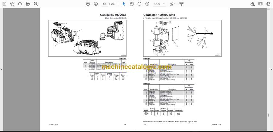
Contactor, 100 Amp . . . . . . . . . . . . . . . . . . . . . . . . . . . . . . . . . . . . . . . . . . . . . . . . . . . 194
Contactor, 150/200 Amp . . . . . . . . . . . . . . . . . . . . . . . . . . . . . . . . . . . . . . . . . . . . . . . 196
Contactor, 200 Amp . . . . . . . . . . . . . . . . . . . . . . . . . . . . . . . . . . . . . . . . . . . . . . . . . . . 197
Contactor, 300/400 Amp, 2/3 Pole . . . . . . . . . . . . . . . . . . . . . . . . . . . . . . . . . . . . . . . 198
Contactor, 100- 200 Amp . . . . . . . . . . . . . . . . . . . . . . . . . . . . . . . . . . . . . . . . . . . . . . . 199
Contactor, 400 Amp . . . . . . . . . . . . . . . . . . . . . . . . . . . . . . . . . . . . . . . . . . . . . . . . . . . 200
Literature . . . . . . . . . . . . . . . . . . . . . . . . . . . . . . . . . . . . . . . . . . . . . . . . . . . . . . . . . . . . 201
Accessories . . . . . . . . . . . . . . . . . . . . . . . . . . . . . . . . . . . . . . . . . . . . . . . . . . . . . . . . . . 202
Appendix A Abbreviations . . . . . . . . . . . . . . . . . . . . . . . . . . . . . . . . . . . . . . . . . . . . . . . . . . . . . . . . . . . . . . . . 205
Appendix B Common Hardware Application Guidelines . . . . . . . . . . . . . . . . . . . . . . . . . . . . . . . . . . . . . 207
Appendix C General Torque Specifications . . . . . . . . . . . . . . . . . . . . . . . . . . . . . . . . . . . . . . . . . . . . . . . . 208
Appendix D Common Hardware Identification . . . . . . . . . . . . . . . . . . . . . . . . . . . . . . . . . . . . . . . . . . . . . . 209
Appendix E Common Hardware List . . . . . . . . . . . . . . . . . . . . . . . . . . . . . . . . . . . . . . . . . . . . . . . . . . . . . . . 210


