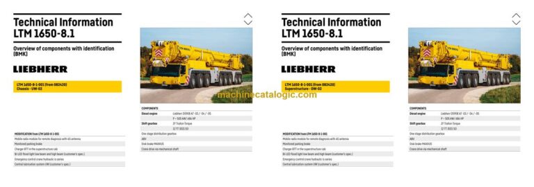
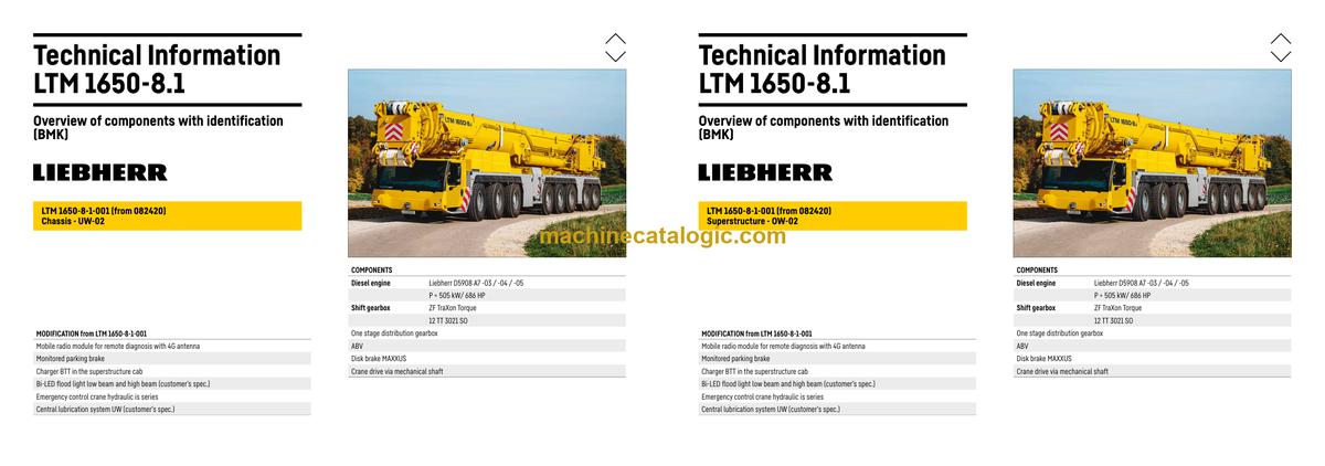
The Liebherr LTM 1650-8.1 is a serious piece of kit, and when it throws an electrical or hydraulic fault, the first thing my guys reach for is the BMK/Technical Information, not the glossy operator’s book. The BMK component identification manual is what ties what you see on the crane to what you see on the schematics. In a real workshop, that’s what saves you wandering around the machine with a multimeter and a guess.
What this manual helps you do
- Identify each Liebherr BMK reference (E…, K…, V…, X…) on the LTM 1650-8.1 and know what component it actually is.
- Locate the physical position of sensors, valves, relays, plugs, and harnesses on both carrier and superstructure from the diagrams.
- Trace a fault from a wiring or hydraulic diagram on your laptop straight to the real-world part on the crane.
- Cross-reference component IDs with other Liebherr documents, so you can jump from BMK to service info or parts ordering.
- Pinpoint what’s mounted where when you’re training new techs or talking a field guy through a repair over the phone.
Who this is for
This is aimed at workshop technicians, field service techs, electrical diagnostic engineers, fleet mechanics, and trainers who already have or use wiring diagrams and service info. If you’re mainly after repair procedures, step‑by‑step troubleshooting, or part numbers, you actually want the service manual and parts catalogue instead.
FAQ
Q: Are the diagrams clear and searchable?
A: These BMK manuals are usually supplied as a clear, zoomable PDF that you can search by component ID or text.
Q: Does it cover both carrier and superstructure on this crane?
A: Yes, this Technical Information & BMK Components Manual covers component identification on both the carrier and the superstructure for SN 082558.
Q: Does it tie in with other Liebherr documentation?
A: Yes, the BMK reference designators are meant to match the IDs in Liebherr wiring diagrams, hydraulic schematics, and parts catalogues.
Bottom line: If you need to know “Where exactly is K15 on this LTM 1650-8.1?” this is the right manual. If you want how-to-repair instructions or part numbers, this is not what you need.
📘 Show Index
Table of Contents:
Carrier — Table of Contents
- Inhaltsverzeichnis
- Fahrzeug:
- Beleuchtung vorne und Rückspiegel
- Beleuchtung und Warnsignalgeber hinten
- Beleuchtung Schiebeholmkasten
- Seitenmarkierungsleuchten rechts
- Seitenmarkierungsleuchten links
- Warnsignalgeber vorne
- Rückfahrkamera
- Rückfahrkamera Schiebeholmkasten
- Masse- / Verteilerstecker im Kabelstrang W6
- Masse- / Verteilerstecker im Kabelstrang W7 / W101
- Masse- / Verteilerstecker im Kabelstrang W100 / W163*
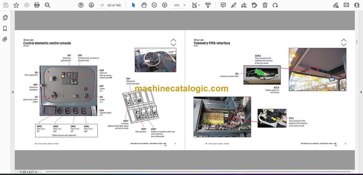
- Fahrerhaus:
- Türen und Fenster, Innenbeleuchtung
- Scheibenwisch- und -waschanlage, Heizventile
- Lüftung und Wärmetauscher
- Zusatzheizung Thermo Pro 90
- Bedienelemente, Sitze
- BTB, Fernsteuermodul BTT
- Bedienelemente Mittelkonsole
- Telemetrie FMS-Schnittstelle
- Telemetrie-Modem, Überwachung Feststellbremse
- Fahrerhaus – Mittelkonsole:
- E/A-Module, BTB und Spannungsversorgung
- Batterien und Batteriehauptschalter
- Sicherungen
- Relais
- Spannungswandler, Heizflanschsteuerung
- Bauteile, Steuergeräte
- Lüfter, NOT-HALT
- Diagnosestecker
- Klimaanlage:
- Übersicht der elektrischen Bauteile
- Druckluftanlage:
- Luftpresser und Lufttrockner
- Druckluft-Vorratsbehälter
- Druckluftventile im Fahrerhaus
- Bremsrelaisventile und Überlastschutzventile
- Überströmventil, Messstellen Druckluftkreise
- Druckgeber und Druckschalter für Achsfederung und Bremsanlage
- Magnetventile Nebenverbraucher
- Übersicht Scheibenbremsanlage
- Übersicht Bremsbelag Überwachung
- Bremsbelag-Überwachungsanzeige
- ABV-Regelventile
- ABV-Raddrehzahlsensoren
- Antriebsaggregat:
- Komplettaggregat Einbauansicht
- Ansicht von rechts
- Ansicht von links
- Dieselmotor D9508 A7 -03 (eAGR) / -04 (SCRonly) / -05 (SCRF)
- Übersicht V-Raum
- Motorsteuergerät
- Übersicht Kraftstoffsystem
- Injektoren LCR-I S2, Typenschilder
- Kraftstoff-Niederdrucksensoren
- Kraftstoffpumpen
- Ladeluftvorwärmung und Ladeluftsensoren
- Abgasturbolader mit Wastegate
- Kühlmittel-Temperatursensor
- Übersicht Schwungradseite
- Drehzahl- und Nockenwellensensor
- Anlasser und Generator
- Übersicht Lüfterseite
- Liebherr-Ölmodul mit Öldrucksensor
- Ölniveausensor und Öltemperatursensor, Sensor Außentemperatur
- Abgasklappe
- Externe Abgasrückführung eAGR
- Intercooler-Temperatursensor
- Abgasanlage „SCRonly“
- Übersicht
- AdBlue-Injektor und Upstream-Sensoren
- Downstream-Sensoren
- Übersicht
- Upstream-Sensoren
- AdBlue-Injektor und Downstream-Sensoren
- Abgasnachbehandlung SCRonly / SCRF
- Harnstofftank und Tanksonde
- Pumpenmodul und AdBlue-Leitungen
- Abgasanlage
- Komponenten Dieselmotor:
- Luftfilteranlage
- Lüfter Motorraum
- Diesel-Kraftstoffanlage
- Kühlanlage:
- TraXon Torque 12 TT 3021 SO:
- Übersicht der Komponenten
- Drehmomentwandler
- Schaltgetriebe TraXon
- Intarder
- Hydraulikversorgung:
- Übersicht Hydraulikpumpen
- Abstützung und Achsfederung
- Druckstufen
- Temperatursensor Hydrauliköl, Hydraulikölbehälter
- Notbetätigung Kranhydraulik – Fahrzeug
- Notbetätigung Kranhydraulik – Abstützung
- Antriebsstrang:
- Übersicht
- Verteilergetriebe – Kessler W3751 PTO (einstufig)
- Umschaltung Fahrantrieb / Kranantrieb (PTO)
- Kranantrieb
- Kranantrieb – Winkelgetriebe
- Querdifferentialsperre Achse 4 und 5
- Längsdifferentialsperren
- Wirbelstrombremse Telma Focal 2200
- Lenkung:
- Lenkgetriebe, Mangelüberwachung
- Ölversorgung Lenkkreis 1, Mangelüberwachung
- Ölversorgung Lenkkreis 2
- Aktive Hinterachslenkung:
- Durchfluss- und Drucküberwachung
- CAN-Ventile Achse 5 und 6
- Steuerblock Achse 5 und 6
- CAN-Ventile Achse 7 und 8
- Steuerblock Achse 7 und 8
- Messpunkte, Hydraulikfilter
- Winkelgeber
- Lenk- und Zentrierzylinder, Sicherheitsventile
- Abstützung
- Neigungsaufnehmer
- Abstützventile – rechts
- Abstützventile – links
- Ausschiebezylinder Schiebeholm
- Abstützzylinder
- VarioBase
- Schiebeholmüberwachung
- Verbolzung Schiebeholmkasten
- Achsfederung:
- Niveaugeber – Achsfederung
- Druckluftventile für die Achsfederung
- Ventilblock – Achsfederung rechts
- Ventilblock – Achsfederung links
- Achsfederungszylinder
- Sonderausstattung:
- Fremdeinspeisung 24 V*, Steckdose 110 V / 230 V*
- Beleuchtung USA*
- Motorvorwärmung* Air Top Evo 55 / Thermo Top Pro 150
- Kühlwasservorwärmung*
- Fremdeinspeisung 110 V / 230 V*
- Umschaltung Membranspeicher rechts*
- Umschaltung Membranspeicher links*
- Batterieladegerät*
- Zusatzabstützung Fahrzeugheck*
- Zentralschmieranlage*
- Selbstmontage Ausleger*- Hubvorrichtung
- Selbstmontage Ausleger*- Transportablage
- Selbstmontage Ausleger*- Rollenbock
- Anhang:
- Index
- Haftungsbegrenzung / Disclaimer
Superstructure — Table of Contents
- Table of contents
- Superstructure general:
- Lighting slewing platform
- Working flood light slewing platform lateral
- Lighting boom
- LMB – warning device (EN 13000)
- Central lubrication system
- Camera monitoring
- Transmission technology and slewing platform left
- Winches and slewing platform right
- Ballasting
- TY-suspension
- Transmission camera signal boom
- Crane cabin:
- Heating – heating air conditioning
- Heating – additional heating Thermo Pro 90
- Heating – activation, temperature sensors
- Air-conditioner
- Wiper motor, washer pump
- Interior furnishing
- Transport position and operating position
- Fittings cab:
- LICCON-monitor, pedals
- Master switch 1, LSB-TE1 right
- Master switch 2, LSB-TE2 left
- Operation- and control unit
- Switch cabinet crane cabin:
- Tilting frame – fuses
- Relay, resistor modules
- Ventilation cab cabinet, voltage converter
- Data logger II, remote diagnosis
- Ethernet Switch
- Diagnosis plug
- Switch cabinet slewing platform:
- LSB – plug-in boards ventilation switch cabinet
- Overview UEA modules
- Overview BTBs
- Tilting frame – fuses
- Release relay, voltage supply
- Relay, earth distribution
- EMERGENCY – socket
- EMERGENCY OPERATION – resistors
- Crane drive:
- Mechanical shaft
- Angle gear box
- Distribution gearbox
- Crane hydraulic:
- Overview hydraulic pumps
- Hydraulic oil tank
- Temperature sensor , oil filter and oil cooler
- Pressure stage valve
- Supply pressure
- Pump 12
- Activation, brake and slewing gear 1
- Slewing gear 2 and 3
- Slewing ring sensor
- Pump and pressure sensor
- Winch 1
- Winch 1* – connections
- Winch 2*
- Winch 2* – connections
- Winch 3*
- Winch 3*- ajustment pulley
- Winch 3 *- connectors
- Pump 7 and 8
- Control block
- Pressure sensor, release luffing down
- Lowering brakes and boom steep
- Swivel joints
- Pump
- Valve block
- Locking slewing platform, flow sensor ballast
- Tilting cab, cab arm slewing
- Slewing gear
- Luffing gear
- Hoist gear
- Supply connections
- Counterweight frame:
- Overview
- Electrical connections, fitted sensors counterweight frame
- Supply connections
- Assembly winch
- Ballasting control block
- Ballasting cylinder
- Slewing cylinder counterweight receptacle
- Telescoping boom – base section
- Behind connections
- Side wise attachments
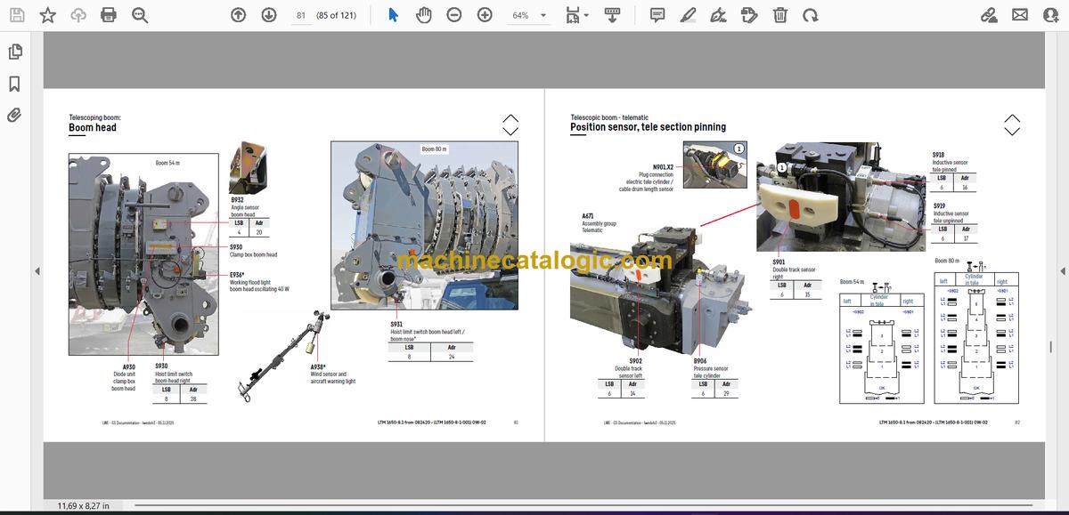
- Boom head
- Position sensor, tele section pinning
- Cylinder pinning, toggle valve
- Emergency operation tele- / cylinder pinning
- Special equipment:
- Oil cooler 2*
- Immobiliser*
- Additional equipment – tele- and luffing cylinder assembly / -disassembly*
- Quick couplings boom
- Quick couplings luffing cylinder
- Activation pinning cylinder
- Pinning cylinder at the slewing platform
- Pinning cylinder at the boom
- Safety valve hydraulic
- Additional equipment – TY-suspension*
- Overview*
- Hydraulic supply*
- Control block TY-frame – adjustment*
- Erection cylinder* and TY-frame steep*
- Adjustment cylinder*
- Angle sensor*
- Control block suspension functions*
- Control block suspension functions*
- Suspension winches*
- Suspension winches – tooth detection*
- Tension cylinder*
- Tension cylinder – sensors*
- Additional equipment – fixed jib*
- TF-adapter*
- TY-adapter* – control block
- Additional equipment – luffing lattice jib*
- N-assembly unit*- angle sensor
- N-assembly unit* – sensors luffing jib up / down
- N-assembly unit*- fall back protection
- N-assembly unit* – A-frame 3
- NA-middle section*
- N-head section* and auxiliary jib*
- Attachment:
- Index
- Limitation of liability / Disclaimer
Liebherr Crane


