Format: PDF (Printable Document)
File Language: English
File Pages: 72
File Size: 9.43 MB (Speed Download Link)
Brand: Kohler
Model: KBS, KBP Automatic Transfer and Bypass, Isolation Switches
Book No: tp6448
Type of Document: Installation Manual
$ 40
These Kohler KBS and KBP automatic transfer and bypass/isolation switches are usually sitting in a plant room or electrical room, quietly handling the swap between utility and generator power. This installation manual is what I keep handy when I’m mounting the switchgear, landing cables, and verifying everything is set up so it transfers cleanly when the lights go out. If, for example, the switch won’t transfer to emergency power after a new install, this is the document I use to trace wiring, confirm mounting orientation, and double-check the installation details before I start blaming the controller or the generator.
Applications & Use Cases
FAQ
Q: Can I keep this manual on a tablet in the electrical room?
A: Yes, it’s practical to use digitally so you can zoom in on diagrams while you’re standing at the switch.
Q: Should I print it out for the job folder?
A: Printing the key pages you reference most often is smart, especially for as-built documentation and inspector walk-throughs.
Safety Note
Always isolate all power sources and verify absence of voltage before removing covers or working inside the switch enclosure.
Safety Precautions and Instructions . . . . . . . . . . . . . . . . . . . . . . . . . . . . . . . . . . . . . . . . . . . . . . . . . . . . . . . . 5
Introduction . . . . . . . . . . . . . . . . . . . . . . . . . . . . . . . . . . . . . . . . . . . . . . . . . . . . . . . . . . . . . . . . . . . . . . . . . . . . . . . 9
List of Related Materials . . . . . . . . . . . . . . . . . . . . . . . . . . . . . . . . . . . . . . . . . . . . . . . . . . . . . 9
Service Assistance . . . . . . . . . . . . . . . . . . . . . . . . . . . . . . . . . . . . . . . . . . . . . . . . . . . . . . . . . . . . . . . . . . . . . . . . 10
Section 1 Product Description . . . . . . . . . . . . . . . . . . . . . . . . . . . . . . . . . . . . . . . . . . . . . . . . . . . . . . . . . . . . . 11
1.1 Purpose . . . . . . . . . . . . . . . . . . . . . . . . . . . . . . . . . . . . . . . . . . . . . . . . . . . . . . . . . . . . . 11
1.2 Nameplate . . . . . . . . . . . . . . . . . . . . . . . . . . . . . . . . . . . . . . . . . . . . . . . . . . . . . . . . . . . 11
1.3 Model Designation . . . . . . . . . . . . . . . . . . . . . . . . . . . . . . . . . . . . . . . . . . . . . . . . . . . . 12
Section 2 Installation . . . . . . . . . . . . . . . . . . . . . . . . . . . . . . . . . . . . . . . . . . . . . . . . . . . . . . . . . . . . . . . . . . . . . . 13
2.1 Introduction . . . . . . . . . . . . . . . . . . . . . . . . . . . . . . . . . . . . . . . . . . . . . . . . . . . . . . . . . . 13
2.2 Receipt of Unit . . . . . . . . . . . . . . . . . . . . . . . . . . . . . . . . . . . . . . . . . . . . . . . . . . . . . . . . 13
2.2.1 Inspection . . . . . . . . . . . . . . . . . . . . . . . . . . . . . . . . . . . . . . . . . . . . . . . . . . . . 13
2.2.2 Lifting . . . . . . . . . . . . . . . . . . . . . . . . . . . . . . . . . . . . . . . . . . . . . . . . . . . . . . . . 13
2.2.3 Storage . . . . . . . . . . . . . . . . . . . . . . . . . . . . . . . . . . . . . . . . . . . . . . . . . . . . . . 14
2.2.4 Unpacking . . . . . . . . . . . . . . . . . . . . . . . . . . . . . . . . . . . . . . . . . . . . . . . . . . . . 14
2.2.5 Remove Transfer Switch Carriage, 4000 Amp Models . . . . . . . . . . . . . . 14
2.3 Installation . . . . . . . . . . . . . . . . . . . . . . . . . . . . . . . . . . . . . . . . . . . . . . . . . . . . . . . . . . . 15
2.3.1 Preparation . . . . . . . . . . . . . . . . . . . . . . . . . . . . . . . . . . . . . . . . . . . . . . . . . . . 15
2.3.2 Mounting . . . . . . . . . . . . . . . . . . . . . . . . . . . . . . . . . . . . . . . . . . . . . . . . . . . . . 15
2.4 Seismic Certification . . . . . . . . . . . . . . . . . . . . . . . . . . . . . . . . . . . . . . . . . . . . . . . . . . . 16
2.5 Transfer Switch Carriage, 4000 Amp Models . . . . . . . . . . . . . . . . . . . . . . . . . . . . . . 17
2.5.1 Transfer Switch Carriage Installation . . . . . . . . . . . . . . . . . . . . . . . . . . . . . 17
2.5.2 Inspections . . . . . . . . . . . . . . . . . . . . . . . . . . . . . . . . . . . . . . . . . . . . . . . . . . . 17
2.6 Controller . . . . . . . . . . . . . . . . . . . . . . . . . . . . . . . . . . . . . . . . . . . . . . . . . . . . . . . . . . . . 19
2.6.1 Controller Connection . . . . . . . . . . . . . . . . . . . . . . . . . . . . . . . . . . . . . . . . . . 19
2.6.2 Controller Ground . . . . . . . . . . . . . . . . . . . . . . . . . . . . . . . . . . . . . . . . . . . . . 19
2.6.3 Other Connections . . . . . . . . . . . . . . . . . . . . . . . . . . . . . . . . . . . . . . . . . . . . 19
2.7 Electrical Wiring . . . . . . . . . . . . . . . . . . . . . . . . . . . . . . . . . . . . . . . . . . . . . . . . . . . . . . . 19
2.7.1 Source and Load Connections . . . . . . . . . . . . . . . . . . . . . . . . . . . . . . . . . . 20
2.7.2 Engine Start Connection . . . . . . . . . . . . . . . . . . . . . . . . . . . . . . . . . . . . . . . 23
2.7.3 Auxiliary Contacts . . . . . . . . . . . . . . . . . . . . . . . . . . . . . . . . . . . . . . . . . . . . . 24
2.8 Accessories . . . . . . . . . . . . . . . . . . . . . . . . . . . . . . . . . . . . . . . . . . . . . . . . . . . . . . . . . . 27
2.9 Programmed-Transition Interface Board (PTIB) . . . . . . . . . . . . . . . . . . . . . . . . . . . . 27
2.10 Functional Tests . . . . . . . . . . . . . . . . . . . . . . . . . . . . . . . . . . . . . . . . . . . . . . . . . . . . . . 28
2.11 System Setup . . . . . . . . . . . . . . . . . . . . . . . . . . . . . . . . . . . . . . . . . . . . . . . . . . . . . . . . 28
2.12 Exerciser Setup . . . . . . . . . . . . . . . . . . . . . . . . . . . . . . . . . . . . . . . . . . . . . . . . . . . . . . . 28
2.13 Startup Notification . . . . . . . . . . . . . . . . . . . . . . . . . . . . . . . . . . . . . . . . . . . . . . . . . . . . 28
Section 3 Functional Tests . . . . . . . . . . . . . . . . . . . . . . . . . . . . . . . . . . . . . . . . . . . . . . . . . . . . . . . . . . . . . . . . . 29
3.1 Introduction . . . . . . . . . . . . . . . . . . . . . . . . . . . . . . . . . . . . . . . . . . . . . . . . . . . . . . . . . . 29
3.2 Manual Operation Test . . . . . . . . . . . . . . . . . . . . . . . . . . . . . . . . . . . . . . . . . . . . . . . . . 29
3.3 Voltage Check . . . . . . . . . . . . . . . . . . . . . . . . . . . . . . . . . . . . . . . . . . . . . . . . . . . . . . . . 29
3.4 Lamp Test . . . . . . . . . . . . . . . . . . . . . . . . . . . . . . . . . . . . . . . . . . . . . . . . . . . . . . . . . . . . 30
3.5 Automatic Operation Test . . . . . . . . . . . . . . . . . . . . . . . . . . . . . . . . . . . . . . . . . . . . . . . 30
Section 4 Bypass, Isolation, and Manual Operation . . . . . . . . . . . . . . . . . . . . . . . . . . . . . . . . . . . . . . . . . . 31
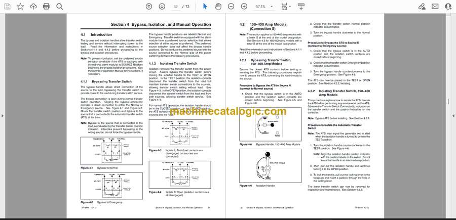
4.1 Introduction . . . . . . . . . . . . . . . . . . . . . . . . . . . . . . . . . . . . . . . . . . . . . . . . . . . . . . . . . . 31
4.1.1 Bypassing Transfer Switch . . . . . . . . . . . . . . . . . . . . . . . . . . . . . . . . . . . . . 31
4.1.2 Isolating Transfer Switch . . . . . . . . . . . . . . . . . . . . . . . . . . . . . . . . . . . . . . . 31
Table of Contents, continued
4 Table of Contents TP-6448 10/12
4.2 150–400 Amp Models (Connection S) . . . . . . . . . . . . . . . . . . . . . . . . . . . . . . . . . . . . 32
4.2.1 Bypassing Transfer Switch, 150–400 Amp Models . . . . . . . . . . . . . . . . . 32
4.2.2 Isolating Transfer Switch, 150–400 Amp Models . . . . . . . . . . . . . . . . . . . 32
4.2.3 Removing Transfer Switch, 150–400 Amp Models . . . . . . . . . . . . . . . . . 33
4.2.4 Reinstalling Transfer Switch, 150–400 Amp Models . . . . . . . . . . . . . . . . 33
4.2.5 Return to Operation, 150–400 Amp Models . . . . . . . . . . . . . . . . . . . . . . . 34
4.2.6 Manual Load Transfer, 150–400 Amp Models . . . . . . . . . . . . . . . . . . . . . 35
4.3 150–600 Amp Models (Connection B) . . . . . . . . . . . . . . . . . . . . . . . . . . . . . . . . . . . . 36
4.3.1 Bypassing ATS,
150–600 Amp Connection B . . . . . . . . . . . . . . . . . . . . . . . . . . . . . . . . . . . . 36
4.3.2 Isolating the Transfer Switch 150–600-Amp Connection B . . . . . . . . . . 39
4.3.3 Return to Service,
150–600 Amp Connection B . . . . . . . . . . . . . . . . . . . . . . . . . . . . . . . . . . . . 41
4.3.4 Return Bypass Switch to OPEN
150–600 Amp Connection B . . . . . . . . . . . . . . . . . . . . . . . . . . . . . . . . . . . . 43
4.3.5 Manual Load Transfer,
150–600 Amp Connection B . . . . . . . . . . . . . . . . . . . . . . . . . . . . . . . . . . . . 44
4.4 600–1200 Amp Models . . . . . . . . . . . . . . . . . . . . . . . . . . . . . . . . . . . . . . . . . . . . . . . . 45
4.4.1 Bypassing ATS, 600–1200 Amps . . . . . . . . . . . . . . . . . . . . . . . . . . . . . . . . 45
4.4.2 Isolating ATS, 600–1200 Amps . . . . . . . . . . . . . . . . . . . . . . . . . . . . . . . . . . 47
4.4.3 Return to Service, 600–1200 Amp Models . . . . . . . . . . . . . . . . . . . . . . . . 49
4.4.4 Return Bypass Switch to OPEN . . . . . . . . . . . . . . . . . . . . . . . . . . . . . . . . . 50
4.4.5 Manual Load Transfer, 600–1200 Amp Models . . . . . . . . . . . . . . . . . . . . 52
4.5 1600–3000 Amp Models . . . . . . . . . . . . . . . . . . . . . . . . . . . . . . . . . . . . . . . . . . . . . . . 53
4.5.1 Bypassing Transfer Switch, 1600–3000 Amp Models . . . . . . . . . . . . . . . 53
4.5.2 Isolating Transfer Switch, 1600–3000 Amp Models . . . . . . . . . . . . . . . . . 54
4.5.3 Removing Transfer Switch, 1600–3000 Amp Models . . . . . . . . . . . . . . . 55
4.5.4 Reinstalling Transfer Switch, 1600–3000 Amp Models . . . . . . . . . . . . . . 55
4.5.5 Return to Operation, 1600–3000 Amp Models . . . . . . . . . . . . . . . . . . . . . 56
4.5.6 Manual Load Transfer, 1600–3000 Amp Models . . . . . . . . . . . . . . . . . . . 58
4.6 4000 Amp Models . . . . . . . . . . . . . . . . . . . . . . . . . . . . . . . . . . . . . . . . . . . . . . . . . . . . . 59
4.6.1 Bypassing Transfer Switch, 4000 Amp Models . . . . . . . . . . . . . . . . . . . . 59
4.6.2 Isolating Transfer Switch, 4000 Amp Models . . . . . . . . . . . . . . . . . . . . . . 59
4.6.3 Removing Transfer Switch, 4000 Amp Models . . . . . . . . . . . . . . . . . . . . . 60
4.6.4 Reinstalling Transfer Switch, 4000 Amp Models . . . . . . . . . . . . . . . . . . . 61
4.6.5 Return to Operation, 4000 Amp Models . . . . . . . . . . . . . . . . . . . . . . . . . . 62
4.6.6 Manual Load Transfer . . . . . . . . . . . . . . . . . . . . . . . . . . . . . . . . . . . . . . . . . . 63
4.7 Manual Operation . . . . . . . . . . . . . . . . . . . . . . . . . . . . . . . . . . . . . . . . . . . . . . . . . . . . . 64
4.7.1 Manual Operation, 150–3000 Amp Models . . . . . . . . . . . . . . . . . . . . . . . . 64
4.7.2 Manual Operation, 4000 Amp Models . . . . . . . . . . . . . . . . . . . . . . . . . . . . 66
Appendix A Abbreviations . . . . . . . . . . . . . . . . . . . . . . . . . . . . . . . . . . . . . . . . . . . . . . . . . . . . . . . . . . . . . . . . . . 69


