Format: PDF (Printable Document)
File Language: English
File Pages: 115
File Size: 6.16 MB (Speed Download Link)
Brand: Kohler
Model: MMT, MNT Automatic Transfer Switches
Book No: tp5974
Type of Document: Service and Parts Manual
$ 40
These Kohler MMT/MNT automatic transfer switches usually sit in electrical rooms or plant rooms, quietly handling the swap between utility and generator power. This manual is what I keep nearby when I’m tracing wiring, swapping components, or confirming I’ve got the right replacement parts before I shut anything down. For example, if a contactor is chattering or a control board looks heat-damaged, I’ll use this book to match the exact assembly, hardware, and subcomponents so I don’t order the wrong style or rating.
Applications & Use Cases
FAQ
Q: Can I use this manual on a tablet or phone at the jobsite?
A: Yes, it’s practical to keep a digital copy so you can zoom in on diagrams while you’re in front of the switch.
Q: Is it worth printing the whole manual?
A: Most techs just print the key parts pages for their model and keep the full manual as a searchable PDF.
Safety Note
Always de-energize and verify absence of voltage on both utility and generator sources before opening or servicing the transfer switch.
Safety Precautions and Instructions . . . . . . . . . i
Introduction . . . . . . . . . . . . . . . . . . . . . . . . . . . . . . . I
List of Related Materials . . . . . . . . . . . . . . . . . . . . . . . . . . I
Service Assistance . . . . . . . . . . . . . . . . . . . . . . . . . II
Service Information . . . . . . . . . . . . . . . . . . . . . . . . . . . . . . II
Product Information . . . . . . . . . . . . . . . . . . . . . . . . . . . . . . II
Section 1. Specifications . . . . . . . . . . . . . . . . . . . 1
1.1 Purpose . . . . . . . . . . . . . . . . . . . . . . . . . . . . . . . . . . 1
1.2 Components . . . . . . . . . . . . . . . . . . . . . . . . . . . . . . 1
1.3 Nameplate . . . . . . . . . . . . . . . . . . . . . . . . . . . . . . . . 2
1.4 Model Number Code . . . . . . . . . . . . . . . . . . . . . . . 3
1.5 Standard Features . . . . . . . . . . . . . . . . . . . . . . . . . 4
1.6 Weights and Dimensions . . . . . . . . . . . . . . . . . . . . 4
1.7 Ratings . . . . . . . . . . . . . . . . . . . . . . . . . . . . . . . . . . . 5
1.8 Application Data . . . . . . . . . . . . . . . . . . . . . . . . . . . 6
Section 2. Operation . . . . . . . . . . . . . . . . . . . . . . . 7
2.1 Startup . . . . . . . . . . . . . . . . . . . . . . . . . . . . . . . . . . . 7
2.2 Operation Sequence . . . . . . . . . . . . . . . . . . . . . . . 8
2.2.1 Transfer to the Emergency Source . . . 8
2.2.2 Transfer to the Normal Source . . . . . . . 8
2.3 Manual Operation . . . . . . . . . . . . . . . . . . . . . . . . . . 9
2.3.1 40–630 Amp Models . . . . . . . . . . . . . . . 9
2.3.2 800–1250 Amp Models . . . . . . . . . . . . . 12
2.4 Resetting Tripped Circuit Breakers . . . . . . . . . . . 13
Section 3. Scheduled Maintenance . . . . . . . . . . 15
3.1 Inspection and Service . . . . . . . . . . . . . . . . . . . . . 16
3.1.1 General Inspection . . . . . . . . . . . . . . . . . 16
3.1.2 Other Inspections and Service . . . . . . . 17
3.2 Testing . . . . . . . . . . . . . . . . . . . . . . . . . . . . . . . . . . . 17
3.2.1 Weekly Generator Set Exercise . . . . . . 17
3.2.2 Monthly Automatic Operation Test . . . . 17
3.3 Service Schedule . . . . . . . . . . . . . . . . . . . . . . . . . . 18
Section 4. Troubleshooting . . . . . . . . . . . . . . . . . 19
4.1 Troubleshooting Charts . . . . . . . . . . . . . . . . . . . . . 20
4.2 Checking Control System Operation . . . . . . . . . . 22
4.2.1 Initial Checks . . . . . . . . . . . . . . . . . . . . . . 22
4.2.2 Transfer to the Emergency Source . . . 23
4.2.3 Transfer to the Normal Source . . . . . . . 25
Section 5. Accessory Testing and Adjustment 27
5.1 Programmed Transition . . . . . . . . . . . . . . . . . . . . . 27
5.1.1 Description . . . . . . . . . . . . . . . . . . . . . . . . 27
5.1.2 Adjustment . . . . . . . . . . . . . . . . . . . . . . . . 28
5.2 Other Accessories . . . . . . . . . . . . . . . . . . . . . . . . . 28
Section 6. Service Part Replacement . . . . . . . . 29
6.1 Introduction . . . . . . . . . . . . . . . . . . . . . . . . . . . . . . . 29
6.2 Before and After Service . . . . . . . . . . . . . . . . . . . . 31
6.3 Power Switching Device Removal and
Installation . . . . . . . . . . . . . . . . . . . . . . . . . . . . . . . . 31
6.3.1 Power Switching Device Removal,
40–1250 Amp Models . . . . . . . . . . . . . . 31
6.3.2 Power Switching Device Installation,
40–1250 Amp Models . . . . . . . . . . . . . . 32
6.4 Mechanical Interlock Removal and Installation,
800–1250 Amp Models . . . . . . . . . . . . . . . . . . . . . 33
6.4.1 Mechanical Interlock Removal,
800–1250 Amp Models . . . . . . . . . . . . . 33
6.4.2 Mechanical Interlock Installation,
800–1250 Amp Models . . . . . . . . . . . . . 34
6.5 Mechanical Interlock Tests . . . . . . . . . . . . . . . . . . 35
6.5.1 40–630 Amp Models . . . . . . . . . . . . . . . 35
6.5.2 800–1250 Amp Models . . . . . . . . . . . . . 37
6.6 Motor Operator Removal and Installation . . . . . . 38
6.6.1 Motor Operator Removal,
40–630 Amp Models . . . . . . . . . . . . . . . 38
6.6.2 Motor Operator Installation,
40–630 Amp Models . . . . . . . . . . . . . . . 39
6.6.3 Motor Operator Removal,
800–1250 Amp Models . . . . . . . . . . . . . 39
6.6.4 Motor Operator Installation,
800–1250 Amp Models . . . . . . . . . . . . . 40
6.7 Circuit Breaker/Switch Removal
and Installation . . . . . . . . . . . . . . . . . . . . . . . . . . . . 42
6.7.1 Circuit Breaker/Switch Removal,
40–1250 Amp Models . . . . . . . . . . . . . . 42
6.7.2 Circuit Breaker/Switch Installation,
40–1250 Amp Models . . . . . . . . . . . . . . 43
6.8 Auxiliary Switch Replacement . . . . . . . . . . . . . . . 44
6.8.1 Auxiliary Switch Removal,
40–630 Amp Models . . . . . . . . . . . . . . . 44
6.8.2 Auxiliary Switch Installation,
40–630 Amp Models . . . . . . . . . . . . . . . 45
6.8.3 Auxiliary Switch Removal,
800–1250 Amp Models . . . . . . . . . . . . . 45
6.8.4 Auxiliary Switch Installation,
800–1250 Amp Models . . . . . . . . . . . . . 46
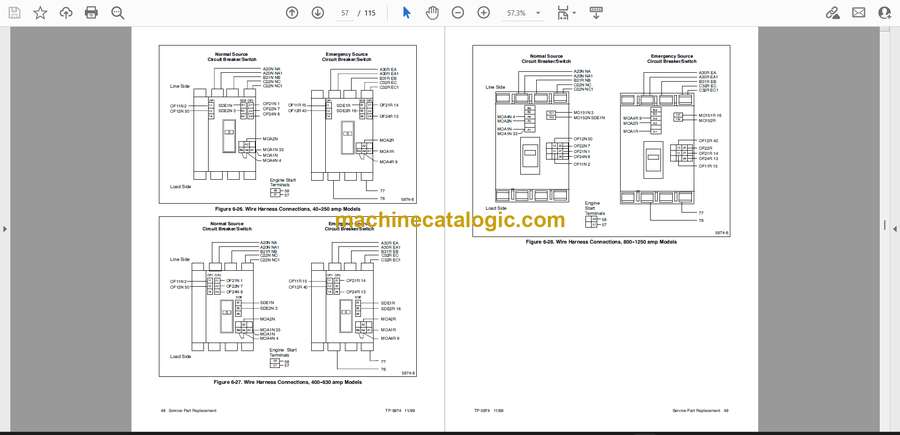
6.9 Wire Harness Replacement . . . . . . . . . . . . . . . . . 47
6.10 Load Bus Replacement . . . . . . . . . . . . . . . . . . . . . 50
6.11 Lug Replacement . . . . . . . . . . . . . . . . . . . . . . . . . . 51
6.11.1 Source Lug Replacement . . . . . . . . . . . 51
6.11.2 Load Lug Replacement . . . . . . . . . . . . . 52
6.12 Voltage Take–Off Replacement . . . . . . . . . . . . . . 53
6.13 Phase Separator Replacement . . . . . . . . . . . . . . 53
Section 7. Diagrams and Drawings . . . . . . . . . . 55
Section 8. Service Parts . . . . . . . . . . . . . . . . . . . . 67
8.1 Finding Parts Information . . . . . . . . . . . . . . . . . . . 67
8.2 Leads . . . . . . . . . . . . . . . . . . . . . . . . . . . . . . . . . . . . 67
8.3 Automatic Transfer Switch . . . . . . . . . . . . . . . . . . 68
8.4 Enclosures . . . . . . . . . . . . . . . . . . . . . . . . . . . . . . . . 69
8.5 Decals . . . . . . . . . . . . . . . . . . . . . . . . . . . . . . . . . . . 70
8.6 Interface Panel Assembly . . . . . . . . . . . . . . . . . . . 71
8.7 Interface Board . . . . . . . . . . . . . . . . . . . . . . . . . . . . 72
8.8 Neutral Lugs . . . . . . . . . . . . . . . . . . . . . . . . . . . . . . 73
8.9 Load Bus Assembly . . . . . . . . . . . . . . . . . . . . . . . . 76
8.10 Power Switch Assemblies . . . . . . . . . . . . . . . . . . . . . 77
Appendix A. Abbreviations . . . . . . . . . . . . . . . . . A-1
Appendix B. Common Hardware Application
Guidelines . . . . . . . . . . . . . . . . . . . . . . . . . . . . . . . . . A-3
Appendix C. General Torque Specifications . . A-4
Appendix D. Common Hardware
Identification . . . . . . . . . . . . . . . . . . . . . . . . . . . . . . . A-5
Appendix E. Common Hardware List . . . . . . . . A-6


