Takeuchi TB395W Hydraulic Excavator Workshop Manual (CAD0E014) (SN 195000005-)
The TB395W is a wheeled excavator that lives on road jobs, utility work, and tight urban sites where you’re constantly climbing curbs and working around traffic. This workshop manual is what I’d grab when I need the exact sequence to strip, inspect, and reinstall major components without guesswork. For example, if the boom drifts down under load or a travel function is weak, this book walks you through how to trace the fault, verify adjustments, and button everything back up so it’s safe to go back on the street.
Applications & Use Cases
- Plan a major teardown of components like swing, boom, or axle assemblies with a clear order of disassembly and reassembly.
- Trace hydraulic issues by following the recommended checks, so you can isolate a faulty valve, cylinder, or line instead of just swapping parts.
- Inspect wear points on pins, bushings, and structural members and decide what must be replaced before it causes bigger damage.
- Verify correct alignment and routing of hoses, harnesses, and linkages after repairs, reducing the chance of rub-throughs or misoperation.
- Perform post-repair tests to confirm the machine is operating safely before it goes back to road work or lifting pipes around people.
FAQ
Q: Can I keep this manual on a tablet in the service truck?
A: Yes, it’s well-suited for digital use, so you can zoom in on diagrams and search text while you’re beside the machine.
Q: Is it still worth printing parts of it?
A: Definitely; most techs print the procedures they’re following that day so they can mark notes, grease smudges, and torque steps right at the machine.
Safety Note
Always follow the manual’s support, lockout, and pressure-release instructions before loosening any component on the TB395W.
Takeuchi TB395W Hydraulic Excavator Index:
- REVISION HISTORY
- FOREWORD
- Directional terms: front, rear, left, right
- Machine serial number
- Symbols used in this manual
- Manual structure
- 1. SAFETY
- SAFETY ALERT SYMBOL
- SAFETY PRECAUTIONS
- Observe all safety rules
- Wear safe clothing and protective gear
- Install an extinguisher and a first aid kit
- Lockout/Tagout (LOTO)
- Use the correct tools
- Regularly replace the safety-critical parts
- Explosionproof lighting
- Prohibit access by unauthorized persons
- Prepare the work area
- When the canopy is tilted up
- Keep the machine clean
- Stop the engine before performing maintenance
- Keep clear of the moving fan and belt
- When working under the machine
- When working on the machine
- Securing the working equipment
- Secure the engine hood and guard when they are open
- Place heavy components in a stable position
- Caution when filling with fuel or oil
- Preventing Fire and Explosion
- Be careful with hot and pressurized components
- Handling of radiator
- Be careful with oils under pressure
- Release the residual pressure from the hydraulic system before performing maintenance
- Be careful with grease under pressure
- Handling of the accumulator
- Disconnect the battery
- Use caution when handling batteries
- Have a service agent repair welding cracks or other damage
- Checks after maintenance
- Disposing of wastes
- Inspection and maintenance of the tires
- Cautions for handling DEF/AdBlue®
- Always maintain 3 points of contact when getting on and off the machine.
- Cautions when starting the engine
- Do not allow anyone other than the operator on the machine.
- If the cab or canopy is damaged
- Beware of fragments when working with a hammer
- Precautions when performing maintenance on the air conditioner
- CAUTIONS WHEN WORKING
- Before starting work
- When disassembling or assembling
- When removing/installing the hydraulic unit
- When connecting/disconnecting the hoses or pipes
- Handling of seals
- Pressure adjustment for hydraulic devices
- 2. SERVICE DATA
- DIMENSIONAL DRAWING
- Machine dimensions
- Rear blade specification
- Outrigger specification
- Operating range
- SPECIFICATION TABLE
- Performance
- Completed machine dimensions
- Main unit dimensions
- Engine
- Hydraulic equipment
- Control equipment
- Lighting equipment (attachment position)
- Warning and safety equipment
- Instruments
- Names of parts
- Slew equipment
- Lower machinery
- Power transmission equipment
- Wheels and axles
- Steering equipment
- Brake equipment
- Outrigger
- Work equipment
- Work dimensions
- Main construction
- Hydraulic cylinder
- Digging force
- Blade
- TABLE OF MASSES
- Upper structure
- Lower structure
- Attachments
- TABLE OF FUEL AND LUBRICANT
- Fuel
- Lubricant
- DEF/AdBlue®
- Applicable standard for DEF/AdBlue®
- Replenishment amount
- PERFORMANCE EVALUATION STANDARD
- Table of standard values
- Hydraulic pump assignment table
- Hydraulic pump No. P1
- Hydraulic pump No. P2
- Hydraulic pump No. P3
- Hydraulic pump No. P4
- Hydraulic pump No. P5
- Hydraulic pump No. P6
- Hydraulic pump No. P7
- Performance inspection guideline
- 1. Engine speed
- 2. Hydraulic pressure
- 3. Cylinder operating speed
- 4. Slew speed (two turns)
- 5. Slewing stop overrun
- 6. Five-minute slew natural drop
- 7. Slew bearing backlash
- 8. Actual travel speed (10 m / 32.8 ft)
- 9. Parking brake performance
- 10. Main brake performance
- 11. Travel hydraulic brake function
- 12. Steering wheel operation amount (clearance between lower frame and tires)
- 13. Ram operation check
- 14. 1st service auto tank operation check
- 15. Auto pressure release operation check
- 16. Differential lock operation check
- 17. Automatic fan speed control
- 18. Five-minute natural cylinder drop
- 19. Raised body holding performance
- 20. Lever play
- 21. Lever operating force
- 22. Blade levelness
- 23. Blade height
- 24. Outrigger height
- 25. Tire air pressure
- 26. Service flow rate
- 27. Slew bearing play
- TIGHTENING TORQUE
- Hydraulic hose
- Bite-type pipe fitting for steel pipe
- Joint for piping
- Joint for piping (O-ring seal type)
- Bolts and nuts (JIS strength category 10.9)
- HYDRAULIC CIRCUIT DIAGRAM
- Serial No.: 195000005 to 195001186
- Serial No.: 195001187 or later
- ELECTRICAL CIRCUIT DIAGRAM
- Symbols in electrical circuit diagram
- Wire color symbols
- Wire color table
- Schematic diagram
- Serial No.: 195000005 to 195000006
- Serial No.: 195000007 to 195000664
- Serial No.: 195000665 to 195001440
- Serial No.: 195001441 to 195001616
- Serial No.: 195001617 or later
- Description for the engine start/stop circuit
- Description for the power generation/charging circuit
- Power generation/charging
- WIRE HARNESS
- Electrical wiring assembly
- Main unit wiring assembly
- Main unit harness
- Wire harness
- Wire harness
- Wire harness
- Wire harness
- Wire harness
- Floor wiring assembly
- Wire harness
- Wire harness
- Wire harness
- Wire harness
- Control valve wiring assembly
- Engine wiring assembly
- Controller assembly
- Electrical wiring assembly (Joystick steering specification)
- Wire harness
- Wire harness
- Lower structure wiring assembly
- Back camera assembly
- Wire harness
- Wire harness
- Wire harness
- 270° camera assembly
- Wire harness
- Wire harness
- Cable
- Cable
- Cable
- Cable
- Cable
- Cable
- Cable
- Cable
- Boom light assembly (Two-piece boom specification 2-cylinder type Light: 1)
- Wire harness
- Wire harness
- Boom light assembly (Two-piece boom specification 2-cylinder type Lights: 2)
- Wire harness
- Wire harness
- Boom light assembly (Two-piece boom specification 1-cylinder type Light: 1)
- Wire harness
- Wire harness
- Boom light assembly (Two-piece boom specification 1-cylinder type Lights: 2)
- Wire harness
- Wire harness
- Position light assembly
- Cab COMP
- Wire harness
- Wire harness
- Wire harness
- Cab interior assembly
- Cab light assembly
- Cab light assembly (with rain guard)
- Rear light assembly
- Steering column
- Air conditioner unit
- Two-piece boom assembly
- Radio assembly
- Serial No.: 195000005 to 195000664
- Cable
- Cable
- Harness supplied with engine
- Wire harness
- Wire harness
- HYDRAULIC DEVICE LAYOUT DIAGRAM
- 3. FUNCTION
- HYDRAULIC PUMP
- Pump appearance and ports
- Piston pump
- Construction
- Operating principle
- Horsepower control regulator
- Construction
- Operating principle
- Load-sensing control regulator
- HST PUMP
- GEAR PUMP
- CONTROL VALVE
- Construction diagram
- Description of operation
- In neutral position
- During operation
- Decelerator circuit: In neutral position
- Decelerator circuit: During operation
- Load check
- Main relief valve
- Overload relief valve
- PILOT VALVE (CONTROL LEVER)
- EMERGENCY SHUTOFF VALVE
- Overview
- Description of operation
- When the spool is at the neutral position
- When the oil flows from the port A to the port B (from the control valve to the cylinder)
- When oil flows from the port B to the port A (from the cylinder to the control valve)
- When an abnormally high pressure is generated in the cylinder (the relief valve is operated)
- When the valve cannot be operated by the pilot pressure due to an error
- EMERGENCY SHUTOFF VALVE
- Overview
- Description of operation
- When the spool is at the neutral position
- When the oil flows from the port A to the port B
- When the oil flows from the port B to the port A
- When an abnormally high pressure is generated in the cylinder
- When the valve cannot be operated by the pilot pressure due to an error
- SOLENOID VALVE (1ST SERVICE PRESSURE ADJUSTMENT, 1ST SERVICE AUTO TANK)
- Construction diagram
- Operating principle
- Solenoid valve
- Relief valve
- SOLENOID VALVE (2ND SERVICE RELIEF PRESSURE ADJUSTMENT FUNCTION)
- Construction diagram
- Description of operation
- SOLENOID VALVE (LEVER LOCK, 3RD SERVICE)
- Construction diagram
- Solenoid switching/relief function
- When not energized
- When energized
- Check function
- Port C → Port ACC and port B
- Port ACC → Port C
- SOLENOID VALVE (RAM LOCK, 1ST SPEED TRAVEL, 2ND SPEED TRAVEL, DIFFERENTIAL LOCK)
- Construction diagram
- Description of operation
- Solenoid valve
- Pressure reducing valve
- SOLENOID VALVE (BLADE/OUTRIGGER SWITCHING)
- SOLENOID VALVE (REVERSIBLE FAN)
- Construction diagram
- Description of operation
- SOLENOID VALVE (4WS)
- Construction diagram
- Description of operation
- SOLENOID VALVE (3RD SERVICE HARD LOCK)
- SELECTOR VALVE
- SELECTOR VALVE
- Blade cylinder (Extended)
- Outrigger cylinder (Extended)
- BRAKE VALVE
- CHECK VALVE
- Overview
- Description of operation
- Neutral position retention of the check valve
- Operation of the check valve
- CYLINDER
- Operating principle
- Cushion mechanism
- When extended
- When retracted
- TRAVEL MOTOR
- SLEW MOTOR
- Reduction gears
- Hydraulic motor
- Hydraulic valves
- Shockless relief valve
- Check valve
- Timer valve
- Reversal prevention valve
- SWIVEL JOINT
- 4. DISASSEMBLY AND ASSEMBLY
- SERVICE STANDARD
- DRIVE EQUIPMENT
- Construction diagram
- Assembly of engine
- Assembly of hydraulic pump
- Assembly of fuel tank
- Assembly of battery
- Disassembly and assembly
- Removal and installation of the engine
- Removal and installation of the hydraulic pump
- Removal and installation of the HST pump
- Removal and installation of the gear pump assembly
- Bleeding air from the hydraulic pump
- Removal and installation of the fuel tank
- Removal and installation of the battery
- TRAVEL EQUIPMENT
- Construction diagram
- Assembly of tires
- Assembly of mudguards
- 2WS specification
- 4WS specification
- Assembly of mudguards (gapless tire specification)
- 2WS specification
- 4WS specification
- Assembly of ram locks
- Assembly of travel drive system
- 2WS specification
- 4WS specification
- Assembly of lower frame
- Disassembly and assembly
- Removal and installation of the tires
- Retrofit kit for gapless tire mudguards
- 2WS specification
- 4WS specification
- SLEW EQUIPMENT
- Construction diagram
- Assembly of slew motor
- Assembly of slew bearing
- Assembly of swivel joint
- Disassembly and assembly
- Removal and installation of the slew motor
- Removal and installation of the slew bearing
- Removal and installation of the swivel joint
- UPPER FRAME
- Construction diagram
- Assembly of main unit
- Assembly of grease piping
- Assembly of cover
- Assembly of cab mounting
- Assembly of floor plate
- Assembly of operator seat
- Disassembly and assembly
- Removal and installation of the main unit
- Removal and installation of the engine cover assembly
- Removal and installation of the side cover assembly
- Removal and installation of the cab assembly
- CONTROL EQUIPMENT
- Construction diagram
- Assembly of remote control unit
- Assembly of right remote control unit
- Assembly of left remote control unit
- Assembly of pilot piping
- Assembly of right control box
- Assembly of left control box
- Assembly of control lever
- Disassembly and assembly
- Removal and installation of the accumulator
- Connected device: Solenoid valve (lever lock / 3rd service)
- Connected device: Brake valve
- WORK EQUIPMENT
- Construction diagram
- Assembly of arm
- Assembly of two-piece boom
- Assembly of boom swing
- Assembly of blade
- Disassembly and assembly
- Removal and installation of the bucket
- Release of residual pressure
- Removal and installation of the arm assembly
- Removal and installation of the second boom assembly
- Removal and installation of the first boom assembly
- Removal and installation of the boom bracket
- Removal and installation of the blade
- Removal and installation of the outrigger
- Removal and installation of the blade arm
- Removal and installation of only each cylinder
- Removal and installation of the bucket cylinder
- Removal and installation of the arm cylinder
- Removal and installation of the boom cylinder
- Removal and installation of the two-piece boom cylinder
- Removal and installation of the swing cylinder
- Removal and installation of the blade cylinder
- HYDRAULIC OIL TANK
- Construction diagram
- Assembly of hydraulic oil tank
- Disassembly and assembly
- Removal and installation of the hydraulic oil tank
- Oil level inspection and replenishment of the hydraulic oil tank
- Method for bleeding air
- HYDRAULIC PUMP
- Construction diagram
- Piston pump
- Load-sensing control regulator
- Horsepower control regulator
- Disassembly and assembly
- Tools to be used
- Disassembly
- Assembly
- Inspection
- HST PUMP
- GEAR PUMP
- Construction diagram
- Disassembly and assembly
- CONTROL VALVE
- Replacement procedure with the spool kit (part number: 05650-00787)
- CONTROL VALVE
- Construction diagram
- Main relief valve
- Overload relief valve
- Disassembly and assembly
- Procedure for disassembly and assembly
- Inspection and adjustment
- PILOT VALVE
- Construction
- Special tools
- Installation jig A
- Installation jig B
- Disassembly and Assembly
- Inspection and adjustment
- EMERGENCY SHUTOFF VALVE
- SOLENOID VALVE
- Construction diagram
- Disassembly and assembly
- SOLENOID VALVE
- Construction diagram
- Disassembly and assembly
- SOLENOID VALVE
- Construction diagram
- Disassembly and assembly
- Inspection
- SOLENOID VALVE
- Construction diagram
- Disassembly and assembly
- Disassembly
- Assembly
- Adjustment of the set pressure
- SOLENOID VALVE (OUTRIGGER)
- Construction
- Disassembly and assembly
- General precautions
- Disassembly
- Assembly
- Inspection and adjustments
- SOLENOID VALVE
- Construction diagram
- Disassembly and assembly
- SOLENOID VALVE (3RD SERVICE HARD LOCK)
- Construction diagram
- Disassembly and assembly
- Disassembly of solenoid valve
- Assembly of solenoid valve
- SELECTOR VALVE
- Construction
- Disassembly and Assembly
- Inspection and adjustment
- SELECTOR VALVE
- Disassembly and assembly
- Inspection and adjustments
- BRAKE VALVE
- CHECK VALVE
- CYLINDERS
- Construction
- Boom cylinder
- Arm cylinder
- Bucket cylinder
- Dozer blade cylinder
- Swing cylinder
- Adjusting cylinder
- Disassembly and Assembly
- Special tools
- Disassembly
- Assembly
- Inspection and adjustment
- Inspection after disassembly
- Inspection after assembly
- CYLINDER
- Construction diagram
- Two-piece boom cylinder (two-cylinder type)
- Disassembly and assembly
- Tools required
- Disassembly
- Inspection and cleaning
- Assembly
- Bleeding air
- Internal leak test
- TRAVEL MOTOR
- SLEW MOTOR
- Construction
- Reduction gears
- Hydraulic motor
- Relief valve
- Timer valve
- Bypass valve
- Disassembly and assembly
- Inspection and adjustments
- SWIVEL JOINT
- Construction diagram
- Disassembly and assembly
- FRONT AXLE
- REAR AXLE
- TRANSMISSION
- MAIN UNIT HYDRAULIC PIPING & LOWER HYDRAULIC PIPING
- Main unit hydraulic piping
- Construction diagram
- Table of connections
- Lower hydraulic piping
- Construction diagram
- Table of connections
- 5. TROUBLESHOOTING
- TROUBLESHOOTING
- Notes on the malfunction diagnosis and repair
- GENERAL
- The engine does not start.
- 1. Did an error code occur?
- 2. Does the starter motor rotate?
- 3. Is there enough fuel?
- 4. Is the fuel filter clogged?
- The engine speed cannot be increased.
- 1. Did an error code occur?
- All the attachments are inoperable.
- 1. Did a vehicle error code occur?
- 2. Is the specified amount of hydraulic oil available?
- 3. Is the pilot pressure within the standard value range?
- 4. Is the main pressure within the standard value range?
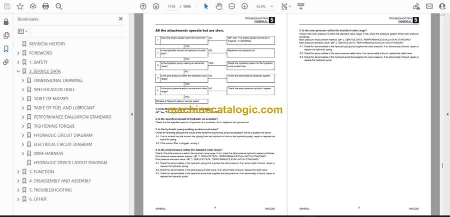
- All the attachments operate but are slow.
- 1. Does the engine speed reach the maximum?
- 2. Is the specified amount of hydraulic oil available?
- 3. Is the hydraulic pump making an abnormal noise?
- 4. Is the pilot pressure within the standard value range?
- 5. Is the main pressure within the standard value range?
- TRAVEL
- The work machine cannot travel.
- 1. Did an error code occur?
- 2. Is the travel speed/differential lock indicator lamp flashing?
- 3. Do travel inputs and outputs occur with the main controller?
- 4. Is the travel pressure normal?
- The variable travel speed cannot be changed.
- 1. Did an error code occur?
- 2. Do variable travel speed inputs and outputs occur with the main controller and lower structure controller?
- SLEW
- Slew operation cannot be performed.
- 1. Is the machine operating normally except for slew?
- 2. Is the slew pressure within the standard value range?
- 3. Is the hydraulic piping that supplies the slew brake release pressure abnormal?
- 4. Does the slew bearing rotate?
- 5. Is the discharge pressure from the pilot valve (for slew operation) normal?
- 6. Is the discharge pressure from the control valve (slew section) normal?
- The left or right slew operation cannot be performed.
- 1. Is the slew pressure within the standard value range?
- 2. Is the hydraulic piping that supplies the slew brake release pressure abnormal?
- 3. Is the discharge pressure from the pilot valve (for slew operation) normal?
- 4. Is the discharge pressure (main pressure) from the control valve (slew section) normal?
- 5. Is the slew relief valve normal?
- The slew operation can be performed but is slow and lacks power.
- 1. Is the machine operating normally except for slew?
- 2. Is the slew pressure below the standard value range?
- 3. Is the slew relief valve or relief valve seat abnormal?
- 4. Is the discharge pressure from the pilot valve (for slew operation) normal?
- 5. Is the discharge pressure from the control valve (slew section) normal?
- The slewing stop overrun is large or the slew operation cannot be stopped.
- 1. Is the slew pressure below the standard value range?
- 2. Can the pilot valve (for slew operation) be set to the neutral position?
- 3. Can the control valve (slew section) be set to the neutral position?
- BOOM
- The first boom cannot be raised or lowered.
- 1. Is the machine operating normally except for the first boom?
- 2. Is the discharge pressure from the pilot valve (for boom operation) normal?
- 3. Is the discharge pressure from the control valve (boom section) normal?
- The first boom can be raised or lowered but is slow and lacks power.
- 1. Is the machine operating normally except for the first boom?
- 2. Is the discharge pressure from the pilot valve (for boom operation) normal?
- 3. Is the discharge pressure from the control valve (boom section) normal?
- 4. Is the boom cylinder leaking internally?
- The boom is temporarily lowered when the boom control lever is slowly pulled.
- 1. Is the boom cylinder leaking internally?
- The amount of first boom natural drop is large.
- 1. Is the boom cylinder leaking internally?
- 2. Is the boom emergency shutoff valve leaking internally?
- ARM
- The arm cannot be pushed or pulled.
- 1. Is the machine operating normally except for the arm?
- 2. Is the discharge pressure from the pilot valve (for arm operation) normal?
- 3. Is the discharge pressure from the control valve (arm section) normal?
- The arm can be pushed and pulled but is slow and lacks power.
- 1. Is the machine operating normally except for the arm?
- 2. Is the discharge pressure from the pilot valve (for arm operation) normal?
- 3. Is the discharge pressure from the control valve (arm section) normal?
- The amount of arm natural drop is large.
- 1. Is the arm emergency shutoff valve leaking internally?
- BUCKET
- The bucket cannot dig or remove soil.
- 1. Is the machine operating normally except for the bucket?
- 2. Is the discharge pressure from the pilot valve (for bucket operation) normal?
- 3. Is the discharge pressure from the control valve (bucket section) normal?
- The bucket can dig and remove soil but is slow and lacks power.
- 1. Is the machine operating normally except for the bucket?
- 2. Is the discharge pressure from the pilot valve (for bucket operation) normal?
- 3. Is the discharge pressure from the control valve (bucket section) normal?
- The amount of bucket natural drop is large.
- 1. Is there an abnormality, such as leaking, in the hydraulic piping connected to the bucket cylinder?
- SWING
- Swing operation cannot be performed.
- 1. Did an error code occur?
- 2. Is the machine operating normally except for swing?
- 3. Do swing inputs and outputs occur with the main controller (XL-FULL) and sub-controller (AUX_CONTROLLER)?
- 4. Is the discharge pressure from the control valve (swing section) normal?
- Swing operation can be performed but is slow and lacks power.
- 1. Is the machine operating normally except for swing?
- 2. Is the discharge pressure from the control valve (swing section) normal?
- The amount of swing natural drop is large.
- 1. Is there an abnormality, such as leaking, in the hydraulic piping connected to the swing cylinder?
- TWO-PIECE BOOM
- The second boom cannot be raised or lowered.
- 1. Did an error code occur?
- 2. Is the machine operating normally except for the second boom?
- 3. Do two-piece boom inputs and outputs occur with the main controller (XL-FULL)?
- 4. Is the discharge pressure from the control valve (two-piece boom section) normal?
- The second boom can be raised or lowered but is slow and lacks power.
- 1. Is the machine operating normally except for the second boom?
- 2. Is the discharge pressure from the control valve (two-piece boom section) normal?
- The amount of second boom natural drop is large.
- 1. Is the two-piece boom emergency shutoff valve leaking internally?
- BLADE
- The blade cannot be raised or lowered.
- 1. Did an error code occur?
- 2. Is the machine operating normally except for the blade?
- 3. Do blade inputs and outputs occur with the main controller (XL-FULL)?
- 4. Is the discharge pressure from the control valve (blade section) normal?
- 5. Is the discharge pressure from the swivel joint normal?
- The blade can be raised or lowered but is slow and lacks power.
- 1. Is the machine operating normally except for the blade?
- 2. Is the discharge pressure from the control valve (blade section) normal?
- 3. Is the discharge pressure from the swivel joint normal?
- The amount of blade natural drop is large.
- 1. Is there an abnormality, such as leaking, in the hydraulic piping connected to the blade cylinder?
- OUTRIGGER
- The outrigger cannot be raised or lowered.
- 1. Did an error code occur?
- 2. Is the machine operating normally except for the outrigger?
- 3. Do outrigger inputs and outputs occur with the main controller (XL-FULL)?
- 4. Is the voltage applied to the solenoid valve (for outrigger)?
- 5. Is the pilot pressure from the solenoid valve (for outrigger) normal?
- The amount of outrigger natural drop is large.
- 1. Is there an abnormality, such as leaking, in the hydraulic piping connected to the blade cylinder?
- SERVICE
- The attachment connected to the 1st service is inoperable.
- 1. Did an error code occur?
- 2. Is the machine operating normally except for the 1st service?
- 3. Do 1st service inputs and outputs occur with the sub-controller (AUX_CONTROLLER)?
- 4. Is the pressure on the 1st service A (left) and B (right) within the standard value range?
- The attachment connected to the 2nd service is inoperable.
- 1. Did an error code occur?
- 2. Is the machine operating normally except for the 2nd service?
- 3. Do 4th service switching button inputs occur with the sub-controller (AUX_CONTROLLER)?
- 4. Do 2nd service inputs and outputs occur with the sub-controller (AUX_CONTROLLER)?
- 5. Is the pressure on the 2nd service A (left) and B (right) within the standard value range?
- The quick-hitch cannot be locked (3rd service).
- 1. Did an error code occur?
- 2. Is the machine operating normally except for the quick-hitch?
- 3. Is the pressure on the 3rd service A (left) within the standard value range?
- 4. Is there an abnormality in the hydraulic piping connected to the 3rd service A (left)?
- The quick-hitch cannot be unlocked (3rd service).
- 1. Did an error code occur?
- 2. Is the machine operating normally except for the quick-hitch?
- 3. Is the pressure on the 3rd service B (right) within the standard value range?
- 4. Do 3rd service inputs and outputs occur with the main controller (XL-FULL) and sub-controller (AUX_CONTROLLER)?
- 5. Is the discharge pressure from the solenoid valve (3rd service) normal?
- HYDRAULIC PUMP
- GEAR PUMP
- CONTROL VALVE
- PILOT VALVE
- SOLENOID VALVE
- SOLENOID VALVE
- SLEW MOTOR
- Hydraulic motor, brake valve
- Parking brake
- 6. OTHER
- MAINTENANCE SOFTWARE MANUAL
- CONTENTS
- 1. OVERVIEW
- 2. CONNECTION METHOD
- 2-1. Parts needed
- 2-2. Installation method
- 2-2-1. Installation of “PLUS+1 Service Tool”
- 2-2-2. Installation of “PLUS+1 Service Tool Drivers”
- 2-3. Connection to the work machine and startup of the maintenance software
- 3. FUNCTION DESCRIPTION
- 3-1. Home
- 3-2. Machine status
- 3-2-1. Location of the controllers
- 3-2-2. Pin wiring of the controllers
- 3-2-3. Inputs(MC) 1
- 3-2-4. Inputs(MC) 2
- 3-2-5. Inputs(Sub,Uc)
- 3-2-6. Outputs(MC)
- 3-2-7. Outputs(Sub,Uc)
- 3-2-8. CAN
- 3-2-9. Feedback
- 3-2-10. Ctrl power
- 3-2-11. Error code
- 3-2-12. Vehicle Status
- 3-2-13. Input(Grip)
- 3-3. Engine status
- 3-3-1. Engine Status1
- 3-3-2. Engine Status2
- 3-3-3. Standstill
- 3-4. Settings
- 3-4-1. AUX1
- 3-4-2. AUX2
- 3-4-3. AUX4
- 3-4-4. Swing
- 3-4-5. Blade
- 3-4-6. Adjust
- 3-4-7. Hourmeter
- 3-4-8. Lift alarm
- 3-4-9. Fan drive
- 3-4-10. Auto Reverse Fan
- 3-4-11. Auto Grease
- 3-4-12. Pattern Change
- 3-4-13. 270deg Camera
- 3-4-14. Engine auto stop
- 3-4-15. Option
- 3-4-16. Misc
- 3-4-17. Extension Output
- 3-4-18. Joystick steering
- AIR CONDITIONER
- Construction diagram
- Assembly of compressor
- Assembly of condenser
- Assembly of air conditioner unit
- Disassembly and assembly
- Removal and installation of the compressor
- Removal and installation of the condenser
- Removal and installation of the receiver dryer
- Removal and installation of the air conditioner unit
- AIR CONDITIONER SYSTEM
- Operating principle
- Disassembly and assembly
- Replacement of air conditioner unit components
- Troubleshooting
- Air conditioner troubleshooting
- About air conditioner troubleshooting
- Basic inspection when air conditioner does not cool
- Air conditioner system status inspection
- How to read the refrigerant pressure on a manifold gauge
- FTA
- Wiring Diagram
- Troubleshooting by symptom
- GRIP BUTTON FUNCTION ASSIGNMENT CHANGE
- Multifunctional grip
- Overview
- Procedure
- Changing the function nameplates
- Standard grip
- Overview
- Procedure
- Changing the function nameplates
- CALIBRATION OF 270° CAMERA
- 1. Overview
- 270° camera calibration
- When calibration is required
- 2. Parts needed
- 3. Calibration procedure
- TABLE OF VEHICLE ERROR CODES
- General
- CAN device
- Multifunctional grip
- Electronic steering valve
- TROUBLESHOOTING BY VEHICLE ERROR CODE
- 9: Key ON detection not possible
- 402: CAN0 communication error
- 412: CAN1 communication error
- 502: CAN communication error (ECU)
- 512: CAN communication error (DEF tank)
- 602: CAN communication error (cluster)
- 672: CAN communication error (sub-controller)
- 677: Incorrect sub-controller part number
- 679: Sub-controller internal error
- 702: CAN communication error (HVAC)
- 812: CAN communication error (switch assembly)
- 822: CAN communication error (immobilizer)
- 832: CAN communication error (dial)
- 842: CAN communication error (radio)
- 852: CAN communication error (left multifunctional grip)
- 862: CAN communication error (right multifunctional grip)
- 872: CAN communication error (lower structure controller)
- 877: Incorrect lower structure controller part number
- 879: Lower structure controller internal error
- 922: CAN communication error (steering controller)
- 929: Steering controller status error
- 1703: Main controller power supply voltage error (high voltage)
- 1704: Main controller power supply voltage error (low voltage)
- 1763: Sub-controller power supply voltage error (high voltage)
- 1764: Sub-controller power supply voltage error (low voltage)
- 1773: Lower structure controller power supply voltage error (high voltage)
- 1774: Lower structure controller power supply voltage error (low voltage)
- 2503: Main controller sensor voltage error (high voltage)
- 2504: Main controller sensor voltage error (low voltage)
- 2563: Sub-controller sensor voltage error (high voltage)
- 2564: Sub-controller sensor voltage error (low voltage)
- 2573: Lower structure controller sensor voltage error (high voltage)
- 2574: Lower structure controller sensor voltage error (low voltage)
- 3300: Alternator charge fault
- 3360: DPF full (Lv2)
- 3401: Engine oil pressure error
- 3500: Overheating
- 3600: Air cleaner clogging
- 3700: Water separator error
- 3810: Line filter clogging
- 3820: Hydraulic oil overheating
- 3825: Hydraulic oil temperature sensor wiring break
- 5303: Accelerator sensor error (short circuit)
- 5304: Accelerator sensor error (break in wiring)
- 5313: Travel pedal sensor error (high voltage)
- 5314: Travel pedal sensor error (low voltage)
- 5317: Travel pedal sensor neutral position error
- 5318: Travel pedal sensor error (drift 1)
- 5319: Travel pedal sensor error (drift 2)
- 5503: Fuel sender voltage error (high voltage)
- 5504: Fuel sender voltage error (low voltage)
- 5603: Lift alarm sensor error (short circuit)
- 5604: Lift alarm sensor error (break in wiring)
- 5683: Swing pedal voltage error (high voltage)
- 5684: Swing pedal voltage error (low voltage)
- 5688: Swing pedal voltage error (drift)
- 5689: Swing pedal neutral position error
- 5693: Blade lever voltage error (high voltage)
- 5694: Blade lever voltage error (low voltage)
- 5698: Blade lever voltage error (drift)
- 5699: Blade lever neutral position error
- 5963: Front wheel brake pressure sensor voltage error (high voltage)
- 5964: Front wheel brake pressure sensor voltage error (low voltage)
- 5968: Brake pressure sensor validity error
- 5973: Rear wheel brake pressure sensor voltage error (high voltage)
- 5974: Rear wheel brake pressure sensor voltage error (low voltage)
- 5983: Brake accumulator pressure sensor voltage error (high voltage)
- 5984: Brake accumulator pressure sensor voltage error (low voltage)
- 5993: Main control valve pressure sensor voltage error (high voltage)
- 5994: Main control valve pressure sensor voltage error (low voltage)
- 6003: Sub control valve pressure sensor voltage error (high voltage)
- 6004: Sub control valve pressure sensor voltage error (low voltage)
- 6503: Left grip slide switch voltage error (high voltage)
- 6504: Left grip slide switch voltage error (low voltage)
- 6509: 1st service slide switch neutral position error
- 6519: 1st service (A) button error
- 6529: 1st service (B) button error
- 6603: Right grip slide switch voltage error (high voltage)
- 6604: Right grip slide switch voltage error (low voltage)
- 6609: 2nd service slide switch neutral position error
- 6709: 3rd service button error (grip)
- 6719: 3rd service switch error (foot)
- 6809: Ram lock switch error
- 6829: Travel selection button error
- 6849: Brake pressure sensor error
- 6859: Low grease level
- 6869: Cruise control switch error
- 6879: 2WS/4WS selection switch error
- 6887: Gear shift switch error (gear 1)
- 6897: Gear shift switch error (gear 2)
- 6909: 4th service slide switch neutral position error
- 6947: Differential lock switch error
- 6957: Speed sensor wiring break
- 6989: Boom suspension switch error
- 6999: Multifunctional grip function assignment error (joystick steering)
- 8005: Pump PWM output current error (low current)
- 8015: 1st service (A) PWM output current error (low current)
- 8025: 1st service (B) PWM output current error (low current)
- 8035: 2nd service (C) PWM output current error (low current)
- 8045: 2nd service (D) PWM output current error (low current)
- 8055: Hydraulic fan solenoid output current error (low current)
- 8075: Forward travel HST pump solenoid output current error (low current)
- 8085: Reverse travel HST pump solenoid output current error (low current)
- 8215: Auto tank solenoid current output error
- 8429: Extension output 1 switch error
- 8439: Extension output 2 switch error
- 8449: Extension output 3 switch error
- 8459: Extension output 4 switch error
- 8469: Extension output 5 slide switch neutral position error
- 8465: Extension output 5 (A side) PWM output current error (low current)
- 8475: Extension output 5 (B side) PWM output current error (low current)
- 8715: 1st service pressure SOL output current error (low current)
- 8725: 2nd service pressure SOL output current error (low current)
- 8735: 4th service (G) PWM output current error (low current)
- 8745: 4th service (H) PWM output current error (low current)
- 8795: Second boom raising solenoid output current error (low current)
- 8805: Second boom lowering solenoid output current error (low current)
- 9125: Swing left solenoid output current error (low current)
- 9135: Swing right solenoid output current error (low current)
- 9145: Blade raising solenoid output current error (low current)
- 9155: Blade lowering solenoid output current error (low current)
- 9165: 4WS solenoid current output error
- 9175: 4WS-C solenoid current output error
- 9185: 4WS switching valve detent solenoid current output error
- 9235: Boom suspension 1 current error (low current)
- 9245: Boom suspension 2 current error (low current)
- 9900: TFM parameter change
- TABLE OF ENGINE ERROR CODES
Takeuchi


