Takeuchi TB2150R Hydraulic Excavator Workshop Manual (CP1E025) (SN 514800002-)
The TB2150R is a big excavator that usually lives in tough places—deep trenching on utility jobs, heavy digging on construction sites, or loading out in quarry conditions. This workshop manual is what I’d pull out when a job goes beyond simple checks and you actually have to strip, repair, and correctly put major components back into service. For example, if a boom function starts lagging or drifting under load, I’d use this book to trace the hydraulic circuit, inspect the affected components, and then follow the proper sequence to reinstall and test everything so it’s safe to go back in the trench.
Applications & Use Cases
- Plan major repairs on the upperstructure, undercarriage, and hydraulic systems in a logical, step‑by‑step order.
- Isolate faults like weak travel, slow swing, or erratic attachment movement before you start swapping parts.
- Verify clearances and alignments during component reassembly so pins, bushings, and shafts don’t fail early.
- Route hoses and harnesses correctly after repairs to avoid chafing, pinch points, or misconnection.
- Perform post‑repair checks to confirm the machine is bled, sealed, and operating safely under load.
FAQ
Q: Can I use this manual on a tablet in the field?
A: Yes, it’s practical to keep it on a tablet or laptop so you can zoom diagrams and search quickly right beside the machine.
Q: Is it worth printing sections of this manual?
A: Printing the procedures you’re doing that day is handy—you can mark notes, tape pages to the cab, and keep greasy hands off your device.
Safety Note
Always lock out, support, and relieve all stored energy before you loosen, disconnect, or remove any major component.
Takeuchi TB2150R Hydraulic Excavator Index:
- REVISION HISTORY
- FOREWORD
- Directional terms: front, rear, left, right
- Machine serial number
- Symbols used in this manual
- Manual structure
- 1. SAFETY
- SAFETY ALERT SYMBOL
- SAFETY PRECAUTIONS
- Observe all safety rules
- Wear safe clothing and protective gear
- Install an extinguisher and a first aid kit
- Lockout/Tagout (LOTO)
- Use the correct tools
- Regularly replace the safety-critical parts
- Explosionproof lighting
- Prohibit access by unauthorized persons
- Prepare the work area
- When the canopy is tilted up
- Keep the machine clean
- Stop the engine before performing maintenance
- Keep clear of the moving fan and belt
- When working under the machine
- When working on the machine
- Securing the working equipment
- Secure the engine hood and guard when they are open
- Place heavy components in a stable position
- Caution when filling with fuel or oil
- Preventing Fire and Explosion
- Be careful with hot and pressurized components
- Handling of radiator
- Be careful with oils under pressure
- Release the residual pressure from the hydraulic system before performing maintenance
- Be careful with grease under pressure
- Handling of the accumulator
- Disconnect the battery
- Use caution when handling batteries
- Have a service agent repair welding cracks or other damage
- Checks after maintenance
- Disposing of wastes
- Cautions for handling DEF/AdBlue®
- Always maintain 3 points of contact when getting on and off the machine.
- Cautions when starting the engine
- Do not allow anyone other than the operator on the machine.
- If the cab or canopy is damaged
- Beware of fragments when working with a hammer
- Precautions when performing maintenance on the air conditioner
- CAUTIONS WHEN WORKING
- Before starting work
- When disassembling or assembling
- When removing/installing the hydraulic unit
- When connecting/disconnecting the hoses or pipes
- Handling of seals
- Pressure adjustment for hydraulic devices
- 2. SERVICE DATA
- DIMENSIONAL DRAWING
- Machine dimensions
- Operating range
- SPECIFICATION TABLES
- Performance
- Dimensions of completed machine
- Dimensions of base machine
- Engine
- Hydraulic system
- Operating device
- Slew equipment
- Lower machinery
- Working equipment
- Working dimensions
- Main structure
- Hydraulic cylinder
- Digging force
- Dozer blade
- TABLE OF MASSES
- Upper structure
- Lower structure
- Attachments
- LUBRICANT AND FUEL CHART
- Diesel fuel standards
- Handling DEF/AdBlue®
- PERFORMANCE CRITERIA
- Standard values table
- Hydraulic pump assignment table
- Hydraulic pump No. P1
- Hydraulic pump No. P2
- Hydraulic pump No. P3
- Hydraulic pump No. P4
- Methods for inspecting performance
- 1. Engine speed
- 2. Hydraulic oil pressure
- 3. Cylinder operating speed
- 4. Slew speed (2 rotations)
- 5. Overrun when slewing stops
- 6. Natural travel drop (over 5 min)
- 7. Natural slew drop (over 5 min)
- 8. Travel speed (10 m (32.8 ft))
- 9. Travel speed (5 revolutions)
- 10. Straight-ahead traveling (10 m (32.8 ft))
- 11. Straight travel function check
- 12. Natural cylinder drop
- 13. Backlash
- 14. Lever play
- 15. Crawler tension
- 16. Blade levelness
- 17. Blade height
- 18. Slew bearing play
- TIGHTENING TORQUE
- Hydraulic hose
- Bite-type pipe fitting for steel pipe
- Joint for piping
- Joint for piping (O-ring seal type)
- Bolts and nuts (JIS strength category 10.9)
- HYDRAULIC CIRCUIT DIAGRAM
- Mono-boom specification
- 3rd service hard lock specification
- Serial No.: 514800002 to 514800444
- Serial No.: 514800445 to 514800667
- Serial No.: 514800668 or later
- Other
- Serial No.: 514800002 to 514800444
- Serial No.: 514800445 to 514800667
- Serial No.: 514800668 or later
- Two-piece boom specification
- 3rd service hard lock specification
- Serial No.: 514800002 to 514800444
- Serial No.: 514800445 to 514800667
- Serial No.: 514800668 or later
- Other
- Serial No.: 514800002 to 514800444
- Serial No.: 514800445 to 514800667
- Serial No.: 514800668 or later
- ELECTRICAL CIRCUIT DIAGRAM
- Symbols in electrical circuit diagram
- Wire color symbols
- Wire color table
- Wire types
- Schematic diagram
- Serial No.: 514800002 to 514800098
- Serial No.: 514800099 to 514800205
- Serial No.: 514800206 to 514800216
- Serial No.: 514800217 to 514800258
- Serial No.: 514800259 to 514800360
- Serial No.: 514800361 to 514800365
- Serial No.: 514800366 to 514800501
- Serial No.: 514800502 to 514800667
- Serial No.: 514800668 or later
- WIRE HARNESS
- Electrical wiring assembly
- Serial No.: 514800002 to 514800712
- Main unit wiring assembly 1
- Main unit wiring assembly 2
- Floor wiring assembly
- Engine wiring assembly
- Serial No.: 514800713 or later
- Main unit wiring assembly 1
- Main unit wiring assembly 2
- Floor wiring assembly
- Engine wiring assembly
- Rear camera assembly
- Serial No.: 514800002 to 514800338
- Wire harness
- Wire harness
- Wire harness
- Serial No.: 514800339 or later
- Wire harness
- Wire harness
- Wire harness
- Wire harness
- 270° camera assembly
- Wire harness
- Wire harness
- Cable
- Cable
- Wire harness
- Cable
- Cable
- GPS equipment assembly
- Right control box assembly
- Control valve assembly
- Pump drive assembly
- Boom light assembly
- Cab light assembly
- Cab mounting assembly
- Wire harness
- Wire harness
- Wire harness
- Cab interior assembly
- Harness supplied with engine
- Serial No.: 514800002 to 514800712
- Wire harness
- Wire harness
- Serial No.: 514800713 or later
- Wire harness
- Wire harness
- HYDRAULIC DEVICE LAYOUT DIAGRAM
- 3. FUNCTION
- HYDRAULIC PUMP (MAIN)
- Cylinder block
- Regulator
- PTO group
- HYDRAULIC PUMP (SUB)
- PILOT VALVE (CONTROL LEVER)
- PILOT VALVE (BLADE)
- PILOT VALVE (TRAVEL)
- PILOT VALVE (ADJUSTING)
- PROPORTIONAL SOLENOID VALVE (1ST SERVICE / 2ND SERVICE)
- EMERGENCY SHUT-OFF VALVE (BOOM, ARM)
- SOLENOID VALVE (LEVER LOCK, 2ND SPEED TRAVEL SWITCHING, 1ST SERVICE HIGH-FLOW, 3RD SERVICE)
- Solenoid valve
- Check valve
- SOLENOID VALVE (1ST SERVICE PRESSURE BLEED)
- Solenoid valve
- Electronic proportional relief valve
- SELECTOR VALVE
- SHOCKLESS VALVE
- CYLINDERS (BOOM, ARM, BUCKET, SWING)
- Functions of parts
- Operation
- BLADE CYLINDER
- TRAVEL MOTOR
- Construction diagram
- Reduction gears
- Hydraulic motor
- Reduction gears
- Hydraulic motor unit (brake valve, parking brake, high/low speed 2-stage switching mechanism)
- SLEW MOTOR
- Hydraulic motor
- Relief valve
- Make-up valve
- Parking brake
- Timer valve
- Reduction gears
- SWIVEL JOINT
- 4. DISASSEMBLY AND ASSEMBLY
- SERVICE STANDARDS
- Carrier roller
- Track roller
- Sprocket
- Idler
- Clearance for pin and bushing
- Replacing the pin and bushing
- DRIVE SYSTEM
- Engine
- Radiator
- Construction diagram
- Removing the engine
- Installing the engine
- Hydraulic pump
- Construction diagram
- Removing the hydraulic pump
- Installing the hydraulic pump
- Fuel tank
- Construction diagram
- Removing the fuel tank
- Installing the fuel tank
- Fuel filler pump
- Battery
- Construction diagram
- Removing the battery
- Installing the battery
- TRAVEL SYSTEM
- Track roller
- Carrier roller
- Front idler
- Track adjuster assembly
- Travel motor
- Shoe guide and center guard
- Construction diagram
- Removing the crawler
- Installing the crawler
- Removing a steel crawler or segmented rubber crawler
- Installing a steel crawler or segmented rubber crawler
- Attaching/removing a segmented rubber crawler
- Replacing the crawler
- Removing the carrier roller
- Installing the carrier roller
- Removing the track roller
- Installing the track roller
- Removing the idler and track adjuster
- Installing the idler and track adjuster
- Removing the travel motor
- Installing the travel motor
- SLEW EQUIPMENT
- Slew motor
- Construction diagram
- Removing the slew motor
- Installing the slew motor
- Slew bearing
- Construction diagram
- Removing the slew bearing
- Installing the slew bearing
- Swivel joint
- Construction diagram
- Removing the swivel joint
- Installing the swivel joint
- UPPER FRAME
- Upper frame
- Grease piping
- Construction diagram
- Removing the upper frame
- Installing the upper frame
- Cover
- Construction diagram
- Removing the covers
- Attaching the covers
- Floor plate assembly
- Cab mounting assembly
- Cab interior assembly
- Switch assembly
- Operator seat assembly
- Radio assembly
- Construction diagram
- Removing the cab
- Installing the cab
- Removing the glass window panes
- Installing the glass window panes
- OPERATING DEVICE
- Construction diagram
- Travel lever
- Blade lever
- Pilot valve (R)
- Pilot valve (L)
- Control lever piping (type A (ISO))
- Disassembly and assembly
- Removal and installation of the accumulator
- WORK EQUIPMENT
- Construction diagram
- Assembly of arm
- Assembly of boom
- Assembly of boom cylinder
- Assembly of arm cylinder
- Assembly of blade
- Disassembly and assembly
- Removal and installation of the bucket
- Release of residual pressure
- Removal and installation of the link
- Removal and installation of the arm
- Removal and installation of the boom
- Removal and installation of the blade
- HYDRAULIC TANK
- Construction diagram
- Removing the hydraulic tank
- Installing the hydraulic tank
- Inspecting and refilling the oil in the hydraulic tank
- Bleeding off the air
- HYDRAULIC PUMP
- Construction
- Disassembly and assembly
- Inspection and adjustments
- PILOT VALVE
- Construction
- Special tools
- Installation jig A
- Installation jig B
- Disassembly and assembly
- Inspection and adjustments
- PILOT VALVE (TRAVEL)
- Construction
- Disassembly and Assembly
- Special Jigs
- Disassembly
- Assembly
- Inspection and adjustment
- PILOT VALVE (ADJUSTING, BLADE)
- Construction diagram
- Special jigs
- Disassembly and assembly
- Inspection and adjustment
- PROPORTIONAL CONTROL SOLENOID VALVE
- Construction
- Disassembly and assembly
- Inspection and adjustments
- EMERGENCY SHUTOFF VALVE
- SOLENOID VALVE (LEVER LOCK, 2ND SPEED TRAVEL SWITCHING, 1ST SERVICE HIGH-FLOW, 3RD SERVICE)
- Construction diagram
- Disassembly and assembly
- General precautions
- Disassembly
- Assembly
- Inspection and adjustments
- SOLENOID VALVE (1ST SERVICE PRESSURE BLEED)
- Construction diagram
- Disassembly and assembly
- General precautions
- Disassembly
- Assembly
- SOLENOID VALVE (2ND/4TH SERVICE SWITCHING)
- Construction diagram
- Disassembly and assembly
- General precautions
- Assembly
- Inspection and adjustments
- SELECTOR VALVE
- Construction
- Disassembly and Assembly
- Inspection and adjustment
- SHOCKLESS VALVE
- Construction
- Disassembly and assembly
- Inspection and adjustments
- CYLINDER
- Boom cylinder
- Arm cylinder
- Bucket cylinder
- Disassembly and assembly
- Service standards
- Inspection after assembly
- Tools required
- Special jigs
- Disassembly
- Assembly
- Start-up operation
- Limits on use of parts
- BLADE CYLINDER
- Construction diagram
- Disassembly and assembly
- Service standards
- Inspection after assembly
- Tools required
- Special jigs
- Disassembly
- Assembly
- TRAVEL MOTOR
- Construction diagram
- Assembled cross-sectional view
- Exploded diagram of reduction gearbox
- Exploded diagram of hydraulic motor
- Tools
- Standard tools
- Bolts
- Equipment
- Sealant
- Production tools
- Table of tightening torques
- Table of masses
- Disassembly and assembly
- Preparation
- General precautions
- Disassembly
- Assembly
- Performance verification testing
- SLEW MOTOR
- Construction
- Hydraulic motor
- Reduction gears
- Brake valve
- Special tools
- Disassembly and assembly
- Inspection and adjustments
- SWIVEL JOINT
- Construction
- Disassembly and assembly
- 5. TROUBLESHOOTING
- TROUBLESHOOTING
- Notes on the malfunction diagnosis and repair
- GENERAL
- The engine does not start.
- 1. Did any error code occur?
- 2. Does the starter motor rotate?
- 3. Is there enough fuel?
- 4. Is the fuel filter clogged?
- The engine speed cannot be increased.
- 1. Did any error code occur?
- All the attachments and travel motors are inoperable.
- 1. Did any vehicle error code occur?
- 2. Is the hydraulic oil above the specified amount?
- 3. Is the pilot pressure within the standard value range?
- 4. Is the main pressure within the standard value range?
- All the attachments and travel motors are operable but are slow.
- 1. Does the engine speed reach the maximum?
- 2. Is the hydraulic oil above the specified amount?
- 3. Is abnormal sound coming from the hydraulic pump?
- 4. Is the pilot pressure within the standard value range?
- 5. Is the main pressure within the standard value range?
- TRAVEL
- The travel motors are inoperable (both left and right or one of them).
- 1. Do hydraulic devices other than the travel motor operate?
- 2. Is the discharge pressure from the pilot valve (for travel operation) normal?
- 3. Is the discharge pressure from the control valve (travel section) normal?
- 4. Is the discharge pressure from the swivel joint normal?
- The vehicle veers to one side with the left or right travel speed slowing down when it travels forward or backward.
- 1. Is the tension of the crawler normal?
- 2. Is any foreign matter trapped in the crawler?
- 3. Is the discharge pressure from the pilot valve (for travel operation) normal?
- 4. Is the discharge pressure from the control valve (travel section) normal?
- 5. Is the discharge pressure from the swivel joint normal?
- The travel speed cannot be changed.
- 1. Is the voltage applied to the solenoid valve (for variable travel speed)?
- 2. Is the variable travel speed pressure from the solenoid valve (for variable travel speed) normal?
- 3. Is the variable travel speed pressure (pilot pressure) from the swivel joint normal?
- SLEW
- The vehicle cannot slew.
- 1. Do hydraulic devices other than the slew operate?
- 2. Is the slew pressure within the standard value range?
- 3. Is the hydraulic piping that supplies the slew brake release pressure abnormal?
- 4. Does the slew bearing rotate?
- 5. Is the discharge pressure from the pilot valve (for slew operation) normal?
- 6. Is the discharge pressure from the control valve (slew section) normal?
- The vehicle cannot slew to the left or right.
- 1. Is the slew pressure within the standard value range?
- 2. Is the hydraulic piping that supplies the slew brake release pressure abnormal?
- 3. Is the discharge pressure from the pilot valve (for slew operation) normal?
- 4. Is the discharge pressure (main pressure) from the control valve (slew section) normal?
- 5. Is the slew relief valve normal?
- The vehicle can slew but is slow and less powerful.
- 1. Do hydraulic devices other than the slew operate normally?
- 2. Is the slew pressure below the standard value range?
- 3. Is the slew relief valve or relief valve seat abnormal?
- 4. Is the discharge pressure from the pilot valve (for slew operation) normal?
- 5. Is the discharge pressure from the control valve (slew section) normal?
- The slewing stop flow amount is large or the vehicle cannot stop.
- 1. Is the slew pressure below the standard value range?
- 2. Can the pilot valve (for slew operation) be in the neutral status?
- 3. Can the control valve (slew section) be in the neutral status?
- BOOM
- The boom cannot rise or drop.
- 1. Do hydraulic devices other than the boom operate?
- 2. Is the discharge pressure from the pilot valve (for boom operation) normal?
- 3. Is the discharge pressure from the control valve (boom section) normal?
- The boom can rise and drop but is slow and less powerful.
- 1. Do hydraulic devices other than the boom operate normally?
- 2. Is the discharge pressure from the pilot valve (for boom operation) normal?
- 3. Is the discharge pressure from the control valve (boom section) normal?
- 4. Is the boom cylinder internally leaking?
- The boom drops temporarily when the boom control lever is slowly pulled.
- 1. Is the boom cylinder internally leaking?
- The amount of boom natural drop is large.
- 1. Is the boom cylinder internally leaking?
- 2. Is the boom emergency shutoff valve internally leaking?
- ARM
- The arm cannot be pushed or pulled.
- 1. Do hydraulic devices other than the arm operate?
- 2. Is the discharge pressure from the pilot valve (for arm operation) normal?
- 3. Is the discharge pressure from the control valve (arm section) normal?
- The arm can be pushed and pulled but is slow and less powerful.
- 1. Do hydraulic devices other than the arm operate normally?
- 2. Is the discharge pressure from the pilot valve (for arm operation) normal?
- 3. Is the discharge pressure from the control valve (arm section) normal?
- The amount of arm natural drop is large.
- 1. Is the arm emergency shutoff valve internally leaking?
- BUCKET
- The bucket cannot dig or remove the ground.
- 1. Do hydraulic devices other than the bucket operate?
- 2. Is the discharge pressure from the pilot valve (for bucket operation) normal?
- 3. Is the discharge pressure from the control valve (bucket section) normal?
- The bucket can dig and remove the ground but is slow and less powerful.
- 1. Do hydraulic devices other than the bucket operate normally?
- 2. Is the discharge pressure from the pilot valve (for bucket operation) normal?
- 3. Is the discharge pressure from the control valve (bucket section) normal?
- The amount of bucket natural drop is large.
- 1. Is the hydraulic piping connected to the bucket cylinder failing, such as leaking?
- ADJUSTER (TWO-PIECE BOOM)
- The adjuster cannot rise or drop.
- 1. Do hydraulic devices other than the adjuster operate?
- 2. Is the discharge pressure from the pilot valve (for adjuster operation) normal?
- 3. Is the discharge pressure from the control valve (adjuster section) normal?
- The adjuster can rise and drop but is slow and less powerful.
- 1. Do hydraulic devices other than the adjuster operate normally?
- 2. Is the discharge pressure from the pilot valve (for adjuster operation) normal?
- 3. Is the discharge pressure from the control valve (adjuster section) normal?
- The amount of adjuster natural drop is large.
- 1. Is the adjuster emergency shutoff valve internally leaking?
- BLADE
- The blade does not rise or drop.
- 1. Do hydraulic devices other than the blade operate?
- 2. Is the discharge pressure from the pilot valve (for blade operation) normal?
- 3. Is the discharge pressure from the control valve (blade section) normal?
- 4. Is the discharge pressure from the swivel joint normal?
- The blade can rise and drop but is slow and less powerful.
- 1. Do hydraulic devices other than the blade operate normally?
- 2. Is the discharge pressure from the pilot valve (for blade operation) normal?
- 3. Is the discharge pressure (main pressure) from the control valve (blade section) normal?
- 4. Is the discharge pressure (main pressure) from the swivel joint normal?
- The amount of blade natural drop is large.
- 1. Is the hydraulic piping connected to the blade cylinder failing, such as leaking?
- SERVICE
- The attachment connected to the 1st service is inoperable.
- 1. Do hydraulic devices other than the 1st service operate?
- 2. Is the voltage applied to the proportional solenoid valve (for 1st service)?
- 3. Is the pressure on the 1st service A and B within the standard value range?
- 4. Is the discharge pressure from the proportional solenoid valve (for 1st service) normal?
- The attachment connected to the 2nd service is inoperable.
- 1. Do hydraulic devices other than the 2nd service operate?
- 2. Is the voltage applied to the solenoid valve (for 2nd service and 4th service switching)?
- 3. Is the voltage applied to the proportional solenoid valve (for 2nd service)?
- 4. Is the pressure on the 2nd service A and B within the standard value range?
- 5. Is the discharge pressure from the proportional solenoid valve (for 2nd service) normal?
- 6. Is the discharge pressure from the control valve (2nd service section) normal?
- The quick-hitch cannot be locked (3rd service).
- 1. Do hydraulic devices other than the quick-hitch operate?
- 2. Is the pressure on the 3rd service A normal?
- 3. Is the hydraulic piping connected to the 3rd service A failing?
- The quick-hitch cannot be unlocked (3rd service).
- 1. Do hydraulic devices other than the quick-hitch operate?
- 2. Is the pressure on the 3rd service B within the standard value range?
- 3. Is the voltage applied to the solenoid valve (for 3rd service)?
- 4. Is the discharge pressure from the solenoid valve (for 3rd service) normal?
- PISTON PUMP
- GEAR PUMP
- PILOT VALVE
- CYLINDER
- SLEW MOTOR
- Hydraulic motor, brake valve
- Parking brake
- SWIVEL JOINT
- 6. OTHER
- MAINTENANCE SOFTWARE MANUAL
- CONTENTS
- 1. OUTLINE
- 2. CONNECTION METHODS
- 2-1. Items needed
- 2-2. Installation method
- 2-2-1. Installation of the PLUS+1 Service Tool
- 2-2-2. Installation of the maintenance tool driver
- 2-3. Connection to the machine and startup of the maintenance software
- 3. DESCRIPTION OF FUNCTIONS
- 3-1. Home
- 3-2. Machine status
- 3-2-1. Controller pin wiring diagrams
- 3-2-2. Inputs
- 3-2-3. Outputs
- 3-2-4. Feedback
- 3-2-5. CAN
- 3-2-6. Error code
- 3-2-7. Error code HVAC
- 3-2-8. Vehicle status
- 3-3. Engine status
- 3-3-1. Engine status
- 3-3-2. Standstill
- 3-4. AUX1
- 3-4-1. AUX1
- 3-4-2. Grip setting
- 3-4-3. Stroke setting
- 3-4-4. Current setting
- 3-4-5. Pressure setting
- 3-4-6. Max relief pressure setting
- 3-5. AUX2
- 3-5-1. AUX2/AUX4
- 3-5-2. Grip setting
- 3-5-3. Stroke setting
- 3-5-4. Current setting
- 3-5-5. Pressure setting
- 3-6. Other
- 3-6-1. Fan drive
- 3-6-2. Coolant
- 3-6-3. Hydraulic
- 3-6-4. Ambient
- 3-6-5. Air conditioner
- 3-6-6. Hydraulic pump
- 3-6-7. Standard mode
- 3-6-8. Power mode
- 3-6-9. Travel in power mode
- 3-6-10. Lift alarm
- 3-6-11. Misc
- 3-6-12. Engine auto stop
- 3-6-13. Pattern change
- 3-6-14. Immobilizer
- 3-6-15. Hourmeter
- 3-6-16. Option
- 3-6-17. Auto grease
- 3-6-18. Test mode
- AIR CONDITIONER
- Compressor assembly
- Condenser assembly
- Air conditioner unit assembly
- Air conditioner unit
- Heater
- AIR CONDITIONER SYSTEM
- Overview of System Operation
- Truck and Heavy Equipment Systems
- Air Conditioner—System Operation
- Heater System Operation
- Environmental Effects on System Operation
- Chapter Review
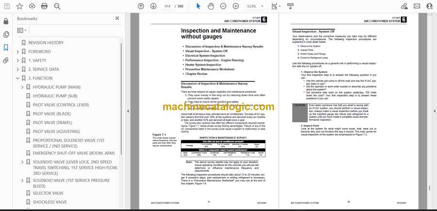
- Inspection and Maintenance without gauges
- Discussion of Inspection & Maintenance Survey Results
- Visual Inspection – System Off
- Electrical System Inspection
- Performance Inspection – Engine Running
- Heater System Inspection
- Preventive Maintenance Worksheet
- Chapter Review
- Troubleshooting & Service Procedures
- Troubleshooting Overview
- The Key–Understanding System Function
- A Troubleshooting Example
- Manifold Gauge Set Installation
- Troubleshooting by Manifold Gauge Set Readings
- Review of Frequent Problem Areas
- Conclusion
- AUTOMATIC TEMPERATURE CONTROL USER’S GUIDE
- FAN DRIVE MOTORS
- CALIBRATION OF 270° CAMERA
- 1. Overview
- 270° camera calibration
- When calibration is required
- 2. Parts needed
- 3. Calibration procedure
- LEVER SWITCH PATTERN SWITCHING METHOD
- Applicable models
- Included parts
- Pattern switching method
- Standard lever switch pattern
- Case 1: When switching the 1st service and the 2nd service
- Case 2: When switching A and B or switching C and D
- Case 3: When switching the 1st service and the 2nd service and also switching A and B or switching C and D
- Case 4: When switching the 1st service and the 2nd service of the slide switch
- VEHICLE ERROR CODES
- Diagnostics procedures for malfunctions and failure
- Repair procedures
- How to check the detection ports
- VEHICLE ERROR CODES
- TABLE OF ENGINE ERROR CODES
Takeuchi


