Takeuchi TL10 Track Loader Workshop Manual (CU6E015) (SN 201000003-)
On a TL10 that’s spending its days grading pads, loading trucks, and working in tight, muddy sites, this workshop manual is what I’d pull out when the job goes beyond simple checks. It walks you through how to strip, inspect, and correctly reinstall major components so the loader goes back to work without odd noises, leaks, or fault lights. For example, if you’ve got a drive motor running hot or making noise, this manual helps you trace the issue, pull the unit safely, and verify everything is aligned and sealed properly on the way back in.
Applications & Use Cases
- Track and undercarriage work – isolate noisy rollers, inspect sprockets, and reinstall components with correct routing and clearances.
- Hydraulic repairs – trace leaks, remove cylinders or pumps, and bleed the system so functions respond smoothly.
- Drive and travel issues – test and verify drive components after replacement to avoid uneven tracking.
- Loader arm and linkage service – inspect pins and bushings, then reassemble so the bucket sits level and cycles cleanly.
- Electrical and sensor troubleshooting – methodically check circuits and refit parts without creating new faults.
FAQ
Q: Can I use this manual on a tablet in the field?
A: Yes, it’s practical to keep it on a tablet; you can zoom diagrams and search text while you’re at the machine.
Q: Is it worth printing sections of this manual?
A: Printing the procedures you use often is handy—oil-stained paper on the bench is better than a dropped phone.
Safety Note
Always lock out the machine, support raised components securely, and follow the manual’s cautions before loosening any major assembly.
Takeuchi TL10 Track Loader Index:
- REVISION HISTORY
- FOREWORD
- Directional terms: front, rear, left, right
- Machine serial number
- Symbols used in this manual
- Manual structure
- 1 SAFETY
- SAFETY ALERT SYMBOL
- SAFETY PRECAUTIONS
- Observe all safety rules
- Wear safe clothing and protective gear
- Install an extinguisher and a first aid kit
- Lockout/Tagout (LOTO)
- Use the correct tools
- Regularly replace the safety-critical parts
- Explosionproof lighting
- Prohibit access by unauthorized persons
- Prepare the work area
- When the canopy is tilted up
- Keep the machine clean
- Stop the engine before performing maintenance
- Keep clear of the moving fan and belt
- When working under the machine
- When working on the machine
- Securing the working equipment
- Secure the engine hood and guard when they are open
- Place heavy components in a stable position
- Caution when filling with fuel or oil
- Handling of hoses
- Be careful with hot and pressurized components
- Handling of radiator
- Be careful with oils under pressure
- Release the residual pressure from the hydraulic system before performing maintenance
- Be careful with grease under pressure
- Handling of the accumulator
- Disconnect the battery
- Use caution when handling batteries
- Have a service agent repair welding cracks or other damage
- Checks after maintenance
- Disposing of wastes
- CAUTIONS WHEN WORKING
- When disassembling or assembling
- When removing/installing the hydraulic unit
- When connecting/disconnecting the hoses or pipes
- Handling of seals
- Pressure adjustment for hydraulic devices
- 2 SERVICE DATA
- Dimensional drawing
- SPECIFICATION TABLE
- Performance
- Dimensions
- Mass
- Engine
- Hydraulic drive system
- Brake device
- Undercarriage
- Operating device
- Working equipment
- Hydraulic system
- LUBRICANT AND FUEL CHART
- PERFORMANCE CRITERIA
- Standard values table
- 201000003 to 201000074
- From 201000075
- Hydraulic pump assignment table
- Pump P1
- Pump P2
- Pump P3
- Pump P4
- Methods for inspecting performance
- Hydraulic oil pressure
- Travel speed (5 revolutions)
- Travel speed (10 m)
- Straight-ahead traveling
- Natural travel drop
- Arm cylinder speed
- Bucket cylinder speed
- Natural cylinder drop
- Track tension
- Level of bucket front edge
- TIGHTENING TORQUE
- Hydraulic hose
- Bite-type pipe fitting for steel pipe
- Joint for piping
- Joint for piping (O-ring seal type)
- Bolts and nuts (JIS strength category 10.9)
- Hydraulic circuit diagram
- Electrical circuit diagram
- WIRE HARNESS DIAGRAM
- 1/4
- 2/4
- 2/4
- 3/4
- 4/4
- CCV heater specifications
- 1/3
- 2/3
- 3/3
- Remove the connector from the ECU
- Relay unit assembly
- Relay unit assembly (CCV heater specification)
- Main harness 06842-16310
- Main harness 06842-00023 (CCV heater specification)
- Wire harness (for the engine): 06942-05620
- Wire harness (for the injector): 06942-05630
- Wire harness (for engine mounting): 06942-05640
- Wire harness (for engine mounting): 06842-00022
- Wire harness (for the DPF): 06942-05650
- Wire harness (14-pin): 06842-16330
- Wire harness (06842-16320)
- Wire harness (06842-00013)
- Wire harness (06842-00014)
- 3 FUNCTION
- HST pump
- Gear pump
- CONTROL VALVE
- Operation when arm-raising operation is activated:
- Operation when arm-lowering operation is activated:
- Operation when the bucket-tilt-backward operation is activated:
- Operation when the arm-float is turned off:
- Operation when the arm-float is activated:
- Load check valve
- Main relief valve
- The relief valve remains turned off:
- The relief valve is activated:
- Port relief valve
- Relief operation:
- Valve suction operation:
- CONTROL VALVE (HIGH-FLOW)
- SUB VALVE
- When the solenoid valve A is not energized:
- When the solenoid valve A is energized:
- When the solenoid valve B is not energized:
- When the solenoid valve B is energized:
- Pilot valve
- PROPORTIONAL SOLENOID VALVE
- Proportional control solenoid valve
- Cylinders
- TRAVEL MOTOR
- Hydraulic motor
- 2-speed mechanism
- During 1st-speed operation:
- During 2nd-speed operation:
- Parking brake
- Flushing valve
- Reduction gears
- 4 DISASSEMBLY AND ASSEMBLY
- SERVICE STANDARDS
- Track roller A
- Track roller B
- Sprocket
- Idler
- Clearance for pin and bushing
- DRIVE SYSTEM
- Engine
- Construction
- Removing the engine
- Installing the engine
- Hydraulic pump
- Construction
- Removing the hydraulic pump
- Installing the hydraulic pump
- Bleeding air from the HST pump
- Fuel tank
- Construction
- Removing the fuel tank
- Installing the fuel tank
- TRAVEL SYSTEM
- Removing the crawler belt
- Installing the crawler belt
- Removing the track roller
- Installing the track roller
- Removing the idler and track adjuster
- Installing the idler and the track adjuster
- Removing the travel motor
- Installing the travel motor
- FRAME
- Tilting up the canopy
- How to raise (tilt up) the canopy
- How to lower the canopy
- Lift arm stopper
- How to install the stopper:
- How to remove the stopper:
- Floor frame
- Construction
- Removing the floor frame
- Installing the floor frame
- Cover
- Construction
- Removing the covers
- Installing the covers
- Canopy/cab
- Construction
- Removing the canopy/cab
- Installing the canopy/cab
- Replacing the glass window panes in the cab
- Construction
- Special tools
- Removing the glass window panes in the cab
- Installing the glass window panes in the cab
- Replace the glass window panes in the front door
- Construction
- Removing the glass window panes in the front door
- Installing the glass window pane in the front door
- OPERATING DEVICE
- ATTACHMENTS
- HYDRAULIC TANK
- HST pump
- GEAR PUMP
- Construction
- Disassembly and assembly
- General precautions
- Disassembly
- Assembly
- Inspection and adjustment
- Checking the parts
- Test operation
- Measuring the discharge volume
- GEAR PUMP (HIGH FLOW)
- Construction
- Disassembly and assembly
- General precautions
- Disassembly
- Assembly
- Inspection and adjustment
- Checking the parts
- Test operation
- Measuring the discharge volume
- Control Valve
- CONTROL VALVE (HIGH-FLOW)
- Construction
- Disassembly and assembly
- General precautions
- Disassembly
- Inspection and adjustments
- SUB VALVE
- Construction
- Disassembly and assembly
- General precautions
- Disassembly
- Inspection and adjustment
- Pilot valve
- PROPORTIONAL CONTROL SOLENOID VALVE
- PROPORTIONAL CONTROL SOLENOID VALVE (ACTIVE POWER CONTROL)
- CYLINDERS
- TRAVEL MOTOR
- Construction
- Hydraulic motor 1/2
- Hydraulic motor 2/2
- Reduction gears
- Special tools
- Disassembly and assembly
- Inspection and adjustment
- 5 TROUBLESHOOTING
- About the troubleshooting section
- OVERALL MACHINE
- TRAVELING
- LIFT ARM
- BUCKET
- AUXILIARY HYDRAULICS
- HST PUMP
- Gear pump
- Control valve
- SUB VALVE
- Pilot valve
- Solenoid valve
- Cylinders
- Travel motor
- 6 Other
- MAINTENANCE SOFTWARE MANUAL
- CONTENTS
- 1. OUTLINE
- 2. CONNECTION METHODS
- 2-1. Items needed
- 2-2. Installation of the PLUS+1 GUIDE Service Tool
- 2-3. Installation of the Maintenance Tool driver
- 2-4. Connection to the machine and startup of the Maintenance Software
- 3. DESCRIPTION OF FUNCTIONS
- 3-1. Home (Main screen)
- 3-2. Status
- 3-2-1. Machine Status
- 3-2-2. Engine Status
- 3-3. Configuration menu
- 3-3-1. AUX1 Settings
- 3-3-2. Other
- AIR CONDITIONER
- AIR CONDITIONER SYSTEM
- Overview of System Operation
- Truck and Heavy Equipment Systems
- Air Conditioner—System Operation
- Heater System Operation
- Environmental Effects on System Operation
- Chapter Review
- Inspection and Maintenance without gauges
- Discussion of Inspection & Maintenance Survey Results
- Visual Inspection – System Off
- Electrical System Inspection
- Performance Inspection – Engine Running
- Heater System Inspection
- Preventive Maintenance Worksheet
- Chapter Review
- Troubleshooting & Service Procedures
- Troubleshooting Overview
- The Key–Understanding System Function
- A Troubleshooting Example
- Manifold Gauge Set Installation
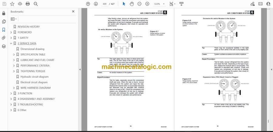
- Troubleshooting by Manifold Gauge Set Readings
- Review of Frequent Problem Areas
- Conclusion
- Electrical wiring diagram
- Option Selection
- Vehicle error codes
Takeuchi


