Takeuchi TB216 Mini Excavator Workshop Manual (CC7E011) (SN 216100002-)
The TB216 is a small excavator that spends its life in tight jobsites—service trenches, landscaping, utilities—often in mud, dust, and cramped access. This workshop manual is what I’d pull out when I have to strip, repair, and correctly put back major components, not just “look it over.” If, for example, the boom won’t hold position or a final drive is seeping oil, this is what I’d use to trace the fault, rebuild the assembly, and verify everything is aligned and sealed before it goes back to work.
Applications & Use Cases
- Planning a repair before teardown so you know what to remove first and what to support, instead of fighting stuck pins and hoses.
- Tracing hydraulic issues like weak travel or slow arm movement with a logical sequence, instead of guessing at which valve or motor is at fault.
- Inspecting wear points on swing, boom, and undercarriage with clear criteria so you don’t miss a cracked bracket or tired bushing.
- Reinstalling major components—motors, cylinders, valve blocks—and verifying routing, torque, and adjustments are safe for full load.
- Checking post-repair operation so you bleed air, test functions, and confirm no leaks or binding before releasing the machine.
FAQ
Q: Is this manual practical to use on a tablet in the field?
A: Yes, it works well digitally; you can zoom diagrams, search terms, and keep it clean while the machine is covered in mud.
Q: Should I still print pages from it?
A: I usually print the key procedures I’m doing that day, mark notes or measurements on them, and keep the originals clean on my computer.
Safety Note
Always follow the manual’s support, lockout, and pressure-release steps before loosening any component on the TB216.
Takeuchi TB216 Mini Excavator Index:
- REVISION HISTORY
- FOREWORD
- Directional terms: front, rear, left, right
- Machine serial number
- Symbols used in this manual
- Manual structure
- 1. SAFETY
- SAFETY ALERT SYMBOL
- SAFETY PRECAUTIONS
- Observe all safety rules
- Wear safe clothing and protective gear
- Install an extinguisher and a first aid kit
- Lockout/Tagout (LOTO)
- Use the correct tools
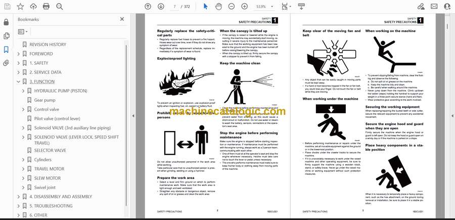
- Regularly replace the safety-critical parts
- Explosionproof lighting
- Prohibit access by unauthorized persons
- Prepare the work area
- When the canopy is tilted up
- Keep the machine clean
- Stop the engine before performing maintenance
- Keep clear of the moving fan and belt
- When working under the machine
- When working on the machine
- Securing the working equipment
- Secure the engine hood and guard when they are open
- Place heavy components in a stable position
- Caution when filling with fuel or oil
- Handling of hoses
- Be careful with hot and pressurized components
- Handling of radiator
- Be careful with oils under pressure
- Release the residual pressure from the hydraulic system before performing maintenance
- Be careful with grease under pressure
- Handling of the accumulator
- Disconnect the battery
- Use caution when handling batteries
- Have a service agent repair welding cracks or other damage
- Checks after maintenance
- Disposing of wastes
- CAUTIONS WHEN WORKING
- Before starting work
- When disassembling or assembling
- When removing/installing the hydraulic unit
- When connecting/disconnecting the hoses or pipes
- Handling of seals
- Pressure adjustment for hydraulic devices
- 2. SERVICE DATA
- Dimensional drawing
- Machine dimensions
- Operating range
- Specification tables
- Performance
- Dimensions of completed machine
- Dimensions of base machine
- Engine
- Hydraulic system
- Operating device
- Slew equipment
- Lower machinery
- Working equipment
- Working dimensions
- Main structure
- Hydraulic cylinder
- Digging force
- Dozer blade
- TABLE OF MASSES
- Upper structure
- Lower structure
- Hoe attachments
- Lubricant and fuel chart
- PERFORMANCE CRITERIA
- Standard values table
- Hydraulic pump assignment table
- Pump P1
- Pump P2
- Pump P3
- Pump P4
- Methods for inspecting performance
- Hydraulic oil pressure (Boom, arm, dozer blade)
- Hydraulic oil pressure (Slew)
- Hydraulic oil pressure (Pilot pressure)
- Travel speed (5 revs.)
- Travel speed (10 m)
- Straight-ahead traveling
- Natural travel drop
- Slew time
- Overrun when slewing stops
- Natural slew drop
- Boom cylinder speed
- Arm cylinder speed
- Bucket cylinder speed
- Dozer blade cylinder speed
- Swing cylinder speed
- Natural cylinder drop
- Swing
- Span cylinder speed
- Lever operating force
- Lever play
- Backlash
- Slew bearing play
- Track tension
- TIGHTENING TORQUE
- Hydraulic hose
- Bite-type pipe fitting for steel pipe
- Joint for piping
- Joint for piping (O-ring seal type)
- Bolts and nuts (JIS strength category 10.9)
- HYDRAULIC CIRCUIT DIAGRAM
- Serial No.: 216100002 to 216000273
- Serial No.: 216100274 or later
- ELECTRICAL CIRCUIT DIAGRAM
- Symbols in electrical circuit diagram
- Wire color symbols
- Wire color table
- Wire types
- Schematic diagram
- Serial No.: 216100002 to 216100502
- Serial No.: 216100503 to 216101377
- Serial No.: 216101378 to 216101581
- Serial No.: 216101582 to 216102019
- Serial No.: 216102020 to 216102235
- Serial No.: 216102236 to 216102241
- Serial No.: 216102242 to 216102404
- Serial No.: 216102405 or later
- Wire harness
- Electrical wiring assembly
- Wire harness
- Serial No.: 216100002 to 216100033
- Serial No.: 216100034 to 216100314
- Serial No.: 216100315 to 216100502
- Serial No.: 216100503 to 216101377
- Serial No.: 216101378 to 216101581
- Serial No.: 216101582 or later
- Wire harness
- Wire harness
- GPS assembly
- Serial No.: 216100002 to 216102217
- Serial No.: 216102218 to 216102446
- Serial No.: 216102447 or later
- Assembly of right control box
- Assembly of control valve
- Wire harness
- Wire harness
- Solenoid valve assembly
- Assembly of boom
- Wire harness
- Wire harness
- Canopy light assembly
- Serial No.: 216100002 to 216100471
- Wire harness
- Wire harness
- Serial No.: 216100472 or later
- Wire harness
- Wire harness
- 3. FUNCTION
- HYDRAULIC PUMP (PISTON)
- Discharge volume control mechanism
- Gear pump
- Control valve
- When the spools are in the neutral position:
- When the spool is being operated:
- Load check valve
- Main relief valves
- The relief valve remains turned off:
- The relief valve is activated:
- Port relief valve
- The relief valve is subjected to the relief operation:
- When the valve is engaged in valve suction operation:
- Anti-cavitation valve
- Anti-drift valve
- Switch valve
- When the switch valve is activated:
- When the switch valve is not activated:
- Arm In regeneration
- Pilot valve (control lever)
- Solenoid VALVE (3rd auxiliary line piping)
- SOLENOID VALVE (LEVER LOCK, SPEED SHIFT TRAVEL)
- Solenoid switching/relief function
- When not energized
- When energized
- Check function
- SELECTOR VALVE
- Cylinders
- TRAVEL MOTOR
- Hydraulic motor
- Counterbalance valve
- 2-speed mechanism
- 2-speed control valve
- Swash plate
- Automatic 2-speed switching
- Parking brake
- Reduction gears
- SLEW MOTOR
- Hydraulic motor 1
- Hydraulic motor 2
- Brake valve
- Parking brake
- Swivel joint
- 4. DISASSEMBLY AND ASSEMBLY
- Service standards
- Track roller
- Shoe slider
- Sprocket
- Idler
- Clearance for pin and bushing
- Replacing the pin and bushing
- DRIVE SYSTEM
- Engine
- Removing the engine
- Installing the engine
- Hydraulic pump
- Removing the hydraulic pump
- Installing the hydraulic pump
- Fuel tank
- Removing the fuel tank
- Installing the fuel tank
- Battery
- Removing the battery
- Installing the battery
- Throttle lever
- Adjusting the throttle lever
- Control force
- Travel system
- Removing the crawler
- Installing the crawler
- Removing the track roller
- Installing the track roller
- Removing the idler and track adjuster
- Installing the idler and track adjuster
- Removing the travel motor
- Installing the travel motor
- Slew equipment
- Slew motor
- Construction
- Removing the slew motor
- Installing the slew motor
- Slew bearing
- Construction
- Removing the slew bearing
- Installing the slew bearing
- Swivel joint
- Construction
- Removing the swivel joint
- Installing the swivel joint
- Upper frame
- Upper frame
- Construction
- Removing the upper frame
- Installing the upper frame
- Covers
- Construction
- Removing the covers
- Installing the covers
- CANOPY
- Construction
- Removing the canopy
- Operating device
- Control lever
- Blade lever
- Lever stand
- Construction diagram
- Hydraulic piping
- Attachments
- Hoe attachment
- Construction
- Removing the hoe attachment
- Hydraulic tank
- Hydraulic tank assembly
- Construction diagram
- Removing the hydraulic tank
- Installing the hydraulic tank
- Hydraulic pump
- Construction
- Disassembly and assembly
- Inspection and adjustments
- CONTROL VALVE
- Construction
- Standard
- Auxiliary 2
- Auxiliary 2 + 3
- Right travel section
- Left travel section
- Swing section
- Boom section
- Slew section
- Arm section
- Bucket section
- Dozer blade section
- Switch valve
- Auxiliary section
- Main relief valve
- Port relief valve
- Anti-cavitation valve
- Disassembly
- Inspection and adjustment
- PILOT VALVE
- Construction
- Special tools
- Installation jig A
- Installation jig B
- Disassembly and Assembly
- Inspection and adjustment
- Proportional control solenoid valve
- Construction
- Disassembly and Assembly
- Inspection and adjustment
- SOLENOID VALVE (3RD AUXILIARY LINE PIPING)
- Construction
- Disassembly and Assembly
- Inspection and adjustment
- SOLENOID VALVE (LEVER LOCK)
- Construction
- Disassembly
- Solenoid valve
- Relief valve
- Check valve
- Assembly
- Inspection and adjustment
- SELECTOR VALVE
- Construction
- Disassembly and Assembly
- Inspection and adjustment
- CYLINDERS
- Construction
- Special tools
- Disassembly
- Assembly
- Inspection and adjustment
- Inspection after assembly
- TRAVEL MOTOR
- Construction
- Hydraulic motor
- Reduction gears
- Valves
- Assembly
- Counter balance valve and hydraulic motor
- Reduction gears
- Inspection and adjustments
- SLEW MOTOR
- Construction
- Hydraulic motor
- Brake valve
- Disassembly and assembly
- Inspection and adjustments
- SWIVEL JOINT
- Construction
- Disassembly and Assembly
- Inspection and adjustment
- Inspection procedures and remedial actions
- Use limit for parts
- Inspection after assembly
- 5. TROUBLESHOOTING
- About the troubleshooting section
- Notes on troubleshooting and servicing
- Overall machine
- No operation is possible.
- All systems working, but insufficient force.
- Boom, bucket, slew and arm fail to move or are too slow.
- Traveling
- No travel is possible.
- Right or left travel is impossible.
- Right or left travel speed decelerates, causing the machine to veer to one side.
- 2nd-speed travel is not possible.
- Slewing
- No slewing is possible.
- Slew right or left is not possible.
- Slewing is slow or lacks force.
- The machine slews, but overruns a lot when slewing stops, or slewing cannot be stopped.
- When stopped on a slope, the upperstructure cannot maintain its posture.
- Boom
- The boom cylinder does not move
- Boom cylinder operation is slow or lacks force.
- Spontaneous drop of the boom cylinder is too large.
- Arm
- Arm cylinder does not move
- Arm cylinder operation is slow or lacks force
- Spontaneous drop of the arm is too large
- Bucket
- Bucket cylinder does not move or lacks force
- Spontaneous drop of the bucket is too large
- Boom swing
- Swing cylinder does not move
- Dozer blade
- Dozer blade cylinder does not move or lacks force.
- The spontaneous drop of the dozer blade is too large, or the dozer blade cannot support the machine
- Auxiliary hydraulics (1st)
- Prescribed pressure is not supplied to the auxiliary lines.
- Spanner
- Spanner cylinder does not move or lacks force
- HYDRAULIC PUMP
- GEAR PUMP
- Control valve
- PILOT VALVE
- Solenoid valve
- Cylinders
- TRAVEL MOTOR
- Hydraulic motor
- 2nd-speed control
- Parking brake
- Slew motor
- Hydraulic motor, brake valve
- Parking brake
- 6. OTHER
- Monochrome LCD Cluster Panel Display and LCD Specifications (Without a CAN)
- Contents
- Normal Panel Display/LCD Screen
- Panel Display: Water Temperature Gauge
- Panel Display: Fuel Gauge
- Panel Display: Function/Warning Lamps
- Normal Screen
- Main Menu screen
- Data Selection Screen
- DATA Screen (TRIP METER)
- DATA Screen (WATER TEMP.)
- Settings Selection Screen
- Setting Screen (CLOCK)
- Setting Screen (ALARM)-1
- Setting Screen (ALARM)-2
- Setting Screen (CONTRAST ADJ.)
Takeuchi


