Takeuchi TB180FR Hydraulic Excavator Workshop Manual (CL5E002) (SN 17830004-)
On a TB180FR that spends its life loading trucks, trenching around utilities, and working tight urban sites, this workshop manual is what I’d keep open on the bench. It walks you through how to strip, inspect, and correctly put back the major systems so the machine goes back to work without surprises. If, for example, the upper structure starts to slew rough or bind, I’d use this manual to trace the fault, verify wear limits with the right checks, and follow the proper sequence to remove, repair, and reinstall components safely.
Applications & Use Cases
- Plan a full teardown of major components so you don’t miss seals, shims, or alignment steps on reassembly.
- Trace hydraulic problems by following the recommended order of checks before you start swapping expensive parts.
- Inspect slew, boom, and undercarriage components using the manual’s guidance to decide what can be reused and what must be replaced.
- Verify adjustments and clearances after reinstallation so travel, swing, and digging functions run smoothly.
- Support parts identification by matching what you see on the machine to the illustrated procedures.
FAQ
Q: Can I use this on a laptop or tablet in the field?
A: Yes, it’s practical to keep it open on a device; zoom in on diagrams and use search to jump to the system you’re working on.
Q: Is it worth printing sections?
A: Many techs print the pages for the job they’re on, mark them up with notes, then keep them in a binder next to the machine.
Safety Note
Always follow the manual’s support, lockout, and pressure relief steps before loosening any component on the TB180FR.
Takeuchi TB180FR Hydraulic Excavator Index:
- TB180FR
- I . GENERAL
- Safety Precautions
- Cautions during Disassembly and Assembly
- Cautions during Removal and Installation of the Hydraulic Units
- Cautions during Removal and Installation of Piping
- Handling of Seals
- Tightening Torques
- II . SPECIFICATIONS
- Names of Components
- Specification Diagrams
- Specification Tables
- Mass Tables
- Recommended Lubricants
- Servicing Standards
- Standards for Judging Performance
- III . MACHINE CONFIGURATION
- Drive System
- Slew System
- Travel System
- Upper Frame
- Control System
- Attachments
- Hydraulic System
- Electrical System
- Interference Prevention System
- Proportional Control
- Air Conditioner System
- Security System
- IV . HYDRAULIC UNITS
- Hydraulic Pump
- Gear Pump
- CONTROL VALVE (MONO-BLOCK)
- Pilot Valve
- Pilot Valve (Travel)
- Pilot Valve (Dozer Blade)
- Pilot Valve (Offset)
- Solenoid Valve (Interference Prevention)
- Solenoid Valve (Lever Lock, Speed Shift)
- Proportional Control Solenoid Valve
- Shut-Off Valves
- Cylinders
- Tensioning Cylinder
- Travel Motor
- Slew Motor
- Swivel Joint
- V . TROUBLESHOOTING
- OVERALL MACHINE
- MACHINE TRAVEL
- SLEWING
- BOOM
- ARM
- BUCKET
- OFFSET
- DOZER BLADE
- AUXILIARY HYDRAULICS
- VI . ENGINE
- 3TNV/4TNV series
- Cover
- History of Revision
- PREFACE
- SAFETY LABELS
- CONTENTS
- 1. General
- 1.1 Engine nomenclature
- 1.2 Specifications
- 1.3 Fuel oil, lubricating oil and cooling water
- 1.3.1 Fuel oil
- 1.3.2 Lubricating oil
- 1.3.3 Cooling water
- 1.4 Engine external views
- 1.5 Structural description
- 1.6 Exhaust gas emission regulation
- 1.6.1 The emission standard in USA
- 1.6.2 Engine identification
- 1.6.3 Guarantee conditions for the EPA emission standard
- 2. Inspection and adjustment
- 2.1 Periodic maintenance schedule
- 2.2 Periodic inspection and maintenance procedure
- 2.2.1 Check before daily operation
- 2.2.2 inspection after initial 50 hours operation
- 2.2.3 Inspection every 50 hours
- 2.2.4 Inspection every 250 hours or 3 months
- 2.2.5 Inspection every 500 hours or 6 months
- 2.2.6 Inspection every 1,000 hours or one year
- 2.2.7 Inspection every 2000 hours or 2 years
- 2.3 Adjusting the no-load maximum or minimum speed
- 2.4 Sensor inspection
- 2.4.1 Oil pressure switch
- 2.4.2 Thermo switch
- 2.5 Water leak check in cooling water system
- 2.6 Radiator cap inspection
- 2.7 Thermostat Inspection
- 2.8 Adjusting operation
- 2.9 Long storage
- 3. Troubleshooting
- 3.1 Preparation before troubleshooting
- 3.2 Quick reference table for troubleshooting
- 3.3 Troubleshooting by measuring compression pressure
- 4. Disassembly, inspection and reassembly of engines
- 4.1 Complete disassembly and reassembly
- 4.1.1 Introduction
- 4.1.2 Special service tools
- 4.1.3 Complete disassembly
- 4.1.4 Precautions before and during reassembly
- 4.1.5 Adjusting operation
- 4.2 Cylinder head: Disassembly, inspection and reassembly
- 4.2.1 Components (2-valve cylinder head)
- 4.2.2 Disassembly procedure:
- 4.2.3 Reassembly procedure:
- 4.2.4 Servicing points
- 4.2.5 Parts Inspection and measurement
- 4.2.6 Valve seat correction
- 4.2.7 Valve guide replacement
- 4.2.8 Valve stem seal replacement
- 4.3 Gear train and camshaft
- 4.3.1 Components
- 4.3.2 Disassembly procedure:
- 4.3.3 Reassembly procedure:
- 4.3.4 Servicing points
- 4.3.5 Parts inspection and measurement
- 4.3.6 Oil seal replacement (Gear case side)
- 4.3.7 Camshaft bushing replacement
- 4.4 Cylinder block
- 4.4.1 Components
- 4.4.2 Disassembly procedure:
- 4.4.3 Reassembly procedure:
- 4.4.4 Servicing points
- 4.4.5 Parts inspection and measurement
- 4.4.6 Cylinder bore correction
- 4.4.7 Piston pin bushing replacement
- 4.4.8 Oil seal replacement (Flywheel housing side)
- 5. Lubrication system
- 5.1 Lubrication system diagram
- 5.2 Trochoid pump components
- 5.3 Disassembly (Reverse the procedure below for assembly)
- 5.4 Servicing points
- 5.5 Parts Inspection and measurement
- 5.5.1 Trochoid pump inspection and measurement
- 5.6 Lube oil filter
- 5.6.1 Lube oil filter construction
- 5.6.2 Lube oil filter replacement
- 6. Cooling system
- 6.1 Cooling water system
- 6.2 Cooling water pump components
- 6.3 Disassembly (Reverse the procedure below for assembly)
- 6.4 Servicing points
- 7. Fuel injection pump / Governor
- 7.1 Introduction
- 7.2 Fuel injection pump
- 7.2.1 Fuel system diagram
- 7.2.2 External view and components
- 7.2.3 Disassembly procedure:
- 7.2.4 Assembly procedure
- 7.2.5 Servicing points
- 7.2.6 C.S.D. (Cold Start Device)
- 8. Turbocharger: Disassembly, inspection and reassembly
- 8.1 Structure and functions
- 8.1.1 Main specifications
- 8.1.2 Construction
- 8.1.3 Structural and functional outline
- 8.1.4 Components
- 8.2 Service standards and tightening torque
- 8.2.1 Service standards
- 8.2.2 Tightening torque
- 8.3 Periodic inspection procedure
- 8.3.1 Periodic inspection intervals
- 8.3.2 Inspection procedure
- 8.3.3 Waste gate valve adjustment procedure
- 8.4 Disassembly procedure
- 8.4.1 Preparation for disassembly
- 8.4.2 Inspection before disassembly
- 8.4.3 Disassembly
- 8.5 Washing and inspection procedure
- 8.5.1 Washing
- 8.5.2 Inspection procedure
- 8.6 Reassembly procedure
- 8.6.1 Preparation for reassembly
- 8.6.2 Reassembly
- 8.7 Handling after disassembly and reassembly
- 8.7.1 Instructions for turbocharger installation
- 8.8 Troubleshooting
- 8.8.1 Excessively exhaust smoke
- 8.8.2 White smoke generation
- 8.8.3 Sudden oil decrease
- 8.8.4 Decrease in output
- 8.8.5 Poor (slow) response (starting) of turbocharger
- 8.8.6 Abnormal sound or vibration
- 9. Starting motror
- 9.1 For 4TNV94L/ 98
- 9.1.1 Specifications
- 9.1.2 Components
- 9.1.3 Troubleshooting
- 9.1.4 Names of parts and disassembly procedure
- 9.1.5 Inspection and maintenance
- 9.1.6 Service standards
- 9.1.7 Assembly
- 9.1.8 Characteristic test
- 9.2 For 4TNV106 (T)
- 9.2.1 Specifications
- 9.2.2 Congiguration drawing
- 9.2.3 Troubleshooting
- 9.2.4 Component names and disassembly procedure
- 9.2.5 Disassembly procedure
- 9.2.6 Inspection and maintenance
- 9.2.7 Assembly
- 9.2.8 Adjustment
- 9.2.9 Service standards
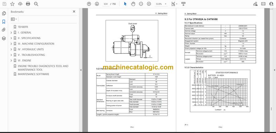
- 9.3 For 3TNV82A to 3/4TNV88
- 9.3.1 Specifications
- 9.3.2 Characteristics
- 9.3.3 Disassembly drawing
- 9.3.4 Connecting diagram of a starting motor
- 10. Alternator
- 10.1 The 40A alternator for 3TNV84 and other models
- 10.1.1 Components
- 10.1.2 Specifications
- 10.1.3 Wiring diagram
- 10.1.4 Standard output characteristics
- 10.1.5 Inspection
- 10.1.6 Troubleshooting
- 11. Electric wiring
- 11.1 Electric wiring diagram
- 11.2 Precaution on electric wiring
- 11.2.1 Alternator
- 11.2.2 Starter
- 11.2.3 Current limiter
- 11.2.4 Section area and resistance of electric wire
- 12. Service standards
- 12.1 Engine tuning
- 12.2 Engine body
- 12.2.1 Cylinder head
- 12.2.2 Gear train and camshaft
- 12.2.3 Cylinder block
- 12.3 Lubricating oil system (Trochoid pump)
- 13. Tightening torque for bolts and nuts
- Back cover
- YPD-MP2/YPD-MP4
- ENGINE TROUBLE DIAGNOSTICS TOOL AND MAINTENANCE TOOL
- MAINTENANCE SOFTWARE
Takeuchi


