Komatsu PW148-11E1 Wheeled Excavator Shop Manual (VENBM77000) (SN H16051-UP)
This Komatsu PW148-11E1 Wheeled Excavator Shop Manual (VENBM77000) is meant for people who actually turn wrenches on these machines, not just drive them. The PW148-11E1 is a road-going wheeled excavator that spends its life on utility work, road jobs, and tight urban sites where downtime kills your schedule. Folks who usually reach for this kind of manual are shop mechanics, field techs, and fleet managers trying to plan repairs, control labor hours, and avoid repeat failures. If you’re trying to move from “firefighting breakdowns” to scheduled, predictable repairs, this is the kind of book you lean on.
What this manual helps you do
- Trace hydraulic issues in the working equipment and travel circuits using the system layouts and step-by-step test procedures you’d expect in a shop manual.
- Diagnose engine, electronic, and sensor faults on the PW148-11E1 with guided troubleshooting flows and wiring information instead of guesswork and parts swapping.
- Follow correct disassembly and reassembly sequences for major components like the swing system, axles, boom/arm, and cylinders so you don’t waste time redoing work.
- Check adjustment points and settings on the working equipment, steering, and braking systems to bring a problem machine back into spec for the next job.
- Handle planned overhauls and mid-life repairs by verifying what needs to come off, what special tools are usually required, and how to stage parts and labor.
Who this is for
This shop manual is aimed at field techs, dealer or independent workshops, and fleet managers who schedule and oversee repairs on Komatsu PW148-11E1 wheeled excavators. Operators looking for daily checks, basic maintenance, or safety instructions would be better off with the Operation & Maintenance Manual instead.
FAQ
Q: Is this a searchable PDF I can download and print?
A: Yes, it’s a digital PDF you can download, search by keyword, and print selected pages for use in the shop.
Q: Does it go deep enough for full component repairs, or just basic service?
A: The Komatsu PW148-11E1 Wheeled Excavator Shop Manual walks through workshop-level diagnostics, teardown/assembly procedures, and adjustment checks, not just routine service tasks.
Q: How do I know if it matches my exact machine version?
A: This manual is written for the PW148-11E1 model; if your ID plate shows a different series or variant, you should confirm coverage by model and book reference VENBM77000 before buying.
Bottom line: if you’re responsible for keeping PW148-11E1 machines earning money and you do your own repairs or supervise them, this is the right manual; if you only need operating tips or basic maintenance intervals, keep looking for the O&M manual instead.
📘 Show Index
Komatsu PW148-11E1 Wheeled Excavator Shop Manual (VENBM77000) (SN H16051-UP) Index:
- VENBM77000 PW148-11E1
- Table of Contents
- Foreword
- Abbreviation List
- List of Abbreviations Used in the Text
- List of Abbreviations Used in the Circuit Diagrams
- Foreword, Safety, Basic Information
- How to Read the Shop Manual
- Composition of the Shop Manual
- Symbols
- Signal Word
- Safety Notice for Operation
- General Precautions
- Preparations for Work
- Precautions During Work
- Hoisting Instructions
- Coating Materials
- Standard Tightening Torque
- Standard Tightening Torque of Bolts and Nuts
- Tightening Torque of Hose Nuts
- Tightening Torque of Split Flange Bolts
- Tightening Torques for Hoses (Taper Seal Type and Face Seal Type)
- Tightening Torque for 107 Engine Series (bolts and nuts)
- Tightening Torque for 107 Engine Series (Eye Joints)
- Tightening Torque for 107 Engine Series (Tapered Screws)
- Electric Wire Code
- Classification by Thickness
- Classification by Color and Code
- Conversion Tables
- Method of Using the Conversion Table
- Units
- Specification
- Specification Dimension Drawings
- Working Ranges
- Working Range: 1-Piece Boom
- Working Range: 2-Piece Boom
- Weight Table
- 1-Piece Boom
- 2-Piece Boom
- Fuel, Coolant, Lubricant
- Structure and Function
- UREA SCR System
- Layout Drawing of UREA SCR System
- Detailed Drawing of ATS Assembly
- Detailed Drawing of DEF Tank
- UREA SCR System Diagram
- Function of UREA SCR System
- Function of DEF System
- DEF Injection Function
- DEF Purge Function
- Function of DEF Thawing and Preventing From Freezing
- Inducement Strategy
- Component Parts of ATS System
- SCR Assembly
- Structure of SCR Assembly
- KDPF
- Structure of KDPF
- DEF Tank
- DEF Pump
- DEF Injector
- DEF Hose
- DEF Tank Heating Valve
- BOOT-UP System
- Layout Drawing of BOOT-UP System
- System Operating Lamp System
- System Operating Lamp System Diagram
- Function of System Operating Lamp System
- Battery Disconnect Switch
- Function of Battery Disconnect Switch
- Function of Battery Disconnect Switch
- Engine System
- Layout Drawing of Engine System
- Engine Control System
- Engine Control System Diagram
- Function of Engine Control System
- Auto-Deceleration System
- Auto-Deceleration system diagram
- Engine Automatic Warm-up System
- Engine Automatic Warm-up System Diagram
- Function of Engine Automatic Warm-up System
- Overheat Prevention System
- Overheat Prevention System Diagram
- Function of Overheat Prevention System
- Turbocharger Protection System
- Turbocharger Protection System Diagram
- Function of Turbocharger Protection System
- Automatic Idle Stop System
- System Diagram of Automatic Idle Stop System
- Function of Automatic Idle Stop System
- Setting Time
- Abrupt Engine Stop Is Detected
- Component Parts of Engine System
- Structure of Turbocharger
- Crankcase Ventilation System
- System Diagram of Crankcase Ventilation System
- Function of Crankcase Ventilation System
- Impactor (Filterless)
- Structure of Impactor (Filterless)
- Operation of Impactor (Filterless)
- Exhaust Throttle Valve
- Structure of Exhaust Throttle Valve
- Cooling system
- Layout Drawing of Cooling System
- Fan Speed Control System of Fan Clutch
- Engine Output Control System of Fan Clutch
- Engine Output Control System Diagram of Fan Clutch
- Function of Engine Output Control System of Fan Clutch
- Component Parts of Cooling System
- Control System
- Machine Monitor System
- System Diagram of Machine Monitor System
- Function of Machine Monitor System
- KomVision System
- Layout Drawing of KomVision System
- Around Cab and Floor
- KomVision System Diagram
- Function of KomVision System
- KOMTRAX System
- KOMTRAX System Diagram
- Function of KOMTRAX System
- Component Parts of Control System
- Machine Monitor
- Monitor Display
- Monitor Items and Display
- Caution Monitor
- Pilot Monitor
- Steering Mode Operation Guidance
- Travel and Road Display Guidance
- Overload Warning Device
- Monitor Switches
- Declaration of Switch Function on Keypad
- Guidance Icon and Function Switch
- Operator Mode Function
- Service Mode Function of Machine Monitor
- Gateway Controller
- Communication Terminal
- KomVision Controller
- Structure of KomVision Controller
- KomVision Camera
- Pump Controller
- Machine Controller
- Engine Controller
- Fuel Control Dial
- Machine Control System Diagram
- 1. Engine and Pump Control Function
- PPC Levers
- LH PPC Lever
- RH PPC Lever
- Power Train System
- Layout Drawing of Power Train System
- Component Parts of Power Train System
- Front Axle
- Rear Axle
- Transmission
- Travel Motor
- Operation of Travel Motor
- Clutch Control Circuit
- Travel System
- Travel Circuit
- Travel Motor Performance
- Travel PPC Pedal
- Swivel Joint
- Braking System
- Structure and Function
- Gear Pump
- Priority Valve
- Power Brake Valve
- Accumulator for Brake Valve
- Digging Brake Valve
- Digging Brake Controller
- Steering System
- Steering System 2WS
- Steering System JSS
- Steering System 4WS
- Steering Column JSS
- Steering Column STD
- Orbitrol Valve STD
- Orbitrol Valve JSS
- Suspension Lock Cylinder (Axle Lock)
- Specifications
- Structure and function
- Circuit
- Axle Oscillation
- Swing System
- Swing Circle
- Swing Machinery & Motor
- Operation of Swing Lock
- Relief Valve Portion
- Work Equipment – Swing PPC Valve
- Undercarriage
- Undercarriage 2WS
- Undercarriage 4WS
- Trailer
- Calculation of Maximum Coupling Load
- Automatic Trailer Coupling for Blade
- Functional Check
- Possible Faults in the Coupling
- Wear Limits
- Automatic Trailer Coupling for Outrigger
- Height Adjustment Components
- Possible Faults in the Coupling
- Wear Limits
- Inspection
- Hydraulic System
- Layout Drawing of Hydraulic System
- CLSS
- Structure of CLSS
- Features of CLSS
- Composition of CLSS
- Function of CLSS
- LS Differential Pressure (ΔPLS) and Pump Swash Plate Angle
- Pressure Compensation Control
- Component Parts of Hydraulic System
- Hydraulic Tank
- Main Pump
- LS Valve
- PC Valve
- 1. LS valve
- LS(PC)-EPC Valve
- Pilot Pressure Control (PPC) System
- Control Valve
- Hydraulic Circuit Diagram and Name of Valves
- 1. Unload Valve
- When the control valve is at neutral, pump discharge amount Q discharged by the minimum swash plate angle is released to the tank circuit. At this time, pump discharge pressure PP is set at 3.38 MPa {34.5 kg/cm²} by spring (3) inside the valve. (LS …
- 2. Introduction of LS Pressure
- 3. LS Bypass Plug
- 4. Pressure Compensation Valve
- 5. Area Ratio of Pressure Compensation Valve
- 6. Boom Regeneration Circuit
- When the boom is lowered and falls due to its own weight because the bottom pressure A in the cylinder (1) is higher than the head pressure B, this circuit brings the return flow on the bottom side to the head side to increase the cylinder speed.
- 7. Arm Regeneration Circuit
- 8. Swing Bleeding Valve
- 9. LS Select Valve
- Solenoid Valve Block
- ATT EPC Assembly
- ON / OFF Solenoid Valves (3 Way Valve)
- ON / OFF Solenoid Valves (4 Way Valve)
- Hi/ Lo Solenoid Valve (4 Way Valve)
- Attachment PPC Valve
- Undercarriage Solenoid Valve Block
- Boom/Outrigger Schematic
- Undercarriage Attachment Schematic
- Proportional Attachment Control
- Proportional Attachment Schematic
- Bucket to 1ATT
- Boom Safety Valve
- Boom Floating
- PPC Pressure Reduction/ Boom Floating Logic
- Tool Control
- Breaker Return Valve
- 1st Attachment Circuit Hydraulic Performance (Main Valve Bypassed)
- Steering Control Solenoid Valve Group
- 2nd Auxiliary Circuit in the Undercarriage
- Hydraulic Quick Coupler
- Hydraulic Quick Coupler Solenoid Valve
- Quick Coupler Error Logic
- Full Hydraulic Quick Coupler
- ECSS
- ECSS Logic
- ECSS Hydraulic Schematic
- ECSS Accumulator Position
- ECSS Valve
- ECSS Hydraulic Diagram
- Work Equipment
- 1. Dimension of Arm
- 2. Dimension of Bucket
- Hydraulic Cylinder
- Boom Cylinder
- Arm Cylinder
- Bucket Cylinder
- Adjust Cylinder
- Outrigger Cylinder
- Dozer Cylinder
- Air Conditioner Unit
- Air Conditioner Component
- Specifications of Air Conditioner
- Sensors
- Ambient Pressure Sensor
- Charge (Boost) Pressure and Temperature Sensor
- Coolant Temperature Sensor
- Ne (Crankshaft) Speed Sensor
- Bkup (Camshaft) Speed Sensor
- Common Rail Pressure Sensor
- Exhaust manifold Pressure Sensor
- TBAP Ambient Pressure and Temperature Sensor
- KDPF Differential Pressure and Outlet Pressure Sensor
- KDOC Inlet Temperature Sensor
- Engine Oil Level Sensor
- Fuel Level Sensor
- WIF (Water-In-Fuel Detection) Sensor
- Coolant Level Sensor
- Hydraulic Oil Temperature Sensor
- Air Cleaner Clogging Sensor
- Overload Caution Sensor
- Swing Proximity Sensor
- Brake Sensors
- Brake Accumulator Low Pressure Sensor (CN-P60)
- Brake Stop Light Sensor (CN-S19)
- Service Brake Pressure Sensor (CN-P64)
- Service Brake Pressure Sensor (CN-P62)
- Park Brake Pressure Sensor (CN-P61)
- PPC Pressure Sensors and Switches
- Main Valve Sensor
- Block Pressure Sensors and Switches
- Lubrication
- Auto-Grease Pump
- Overview
- Display and Control Unit
- LED-Display
- Push Buttons
- Three-Digit LED Display
- Check Central Lubrication System, Fill Up Grease
- Lubrication Diagrams
- Auto-Grease Pump With One-Piece Boom
- Auto-Grease Pump With Two-Piece Boom
- Manual System One-Piece Boom
- Manual System Two-Piece Boom
- Additional Preparations
- Preparation Heatable fuel filter
- Preparation Hydraulic Oil Heater
- Preparation Fuel Pump (Refuelling Pump)
- Standard Value Table
- Standard Value Table for Engine Related Parts
- Standard Value Table for Chassis Related Parts
- Flow Control Characteristic of PC Valve (STD)
- PM Clinic Service
- Testing and Adjusting
- Engine and Cooling System
- Examine Engine Speed
- How to Examine Engine Speed
- Examine Boost Pressure
- How to Examine Boost Pressure on Machine Monitor
- How to Examine Boost Pressure
- Examine Exhaust Gas Color
- How to Examine Exhaust Gas Color with the Handy Smoke Checker
- How to Examine Exhaust Gas Color with Smoke Meter
- Examine and Adjust Valve Clearance
- Check Valve Clearance
- Adjust Valve Clearance
- Examine Compression Pressure
- How to Examine Compression Pressure
- Examine Blowby Pressure
- How to Examine Blowby Pressure
- Examine Engine Oil Pressure
- Examine Fuel Pressure
- How to Examine Fuel Pressure
- Examine Low-Pressure Circuit (Fuel Main Filter Inlet Side)
- Examine Low-Pressure Circuit (Pressure Difference)
- Examine Return Circuit
- Examine Negative Pressure Circuit
- Examine Fuel Discharge, Return and Leakage
- How to Examine Fuel Discharge, Return, and Leakage
- Examine Supply Pump Discharge Volume
- Examine Supply Pump Return Rate
- Examine the Leakage from the Pressure Limiter
- Examine the Return Rate of the Injector
- Bleed Air from Fuel System
- How to Bleed Air from Fuel System
- Examine Fuel Circuit for Leakage
- How to Examine Fuel System for Leakage
- Examine Fuel Circuit for Leakage at Engine Low Idle
- How to Examine Fuel Circuit for Leakage at Engine High Idle
- How to Examine Fuel Circuit for Leakage at Engine Rated Speed
- Handle Cylinder Cut-out Mode Operation
- Handle No-Injection Cranking Operation
- Examine and Adjust Air Conditioner Compressor Belt Tension
- Check air conditioner compressor belt
- How to Adjust Air Conditioner Compressor Belt
- Replace the Fan Belt
- Examine Cooling Fan Speed
- Method for Testing Cooling Fan Speed
- Write Correction for Ash in Soot Accumulation to Engine Controller
- How to Write Correction for Ash in Soot Accumulation to Engine Controller
- Examine SCR Related Functions
- Examine DEF Pump Raised Pressure
- How to Examine DEF Pump Raised Pressure
- Examine Injection Volume from DEF Injector
- How to Examine Injection Volume from DEF Injector
- Examine DEF Line Heater Relay 1
- How to Examine DEF Line Heater Relay 1
- Examine DEF Line Heater Relay 2
- How to Examine DEF Line Heater Relay 2
- Examine DEF Pump Heater Relay
- How to Examine AdBlue/ DEF Pump Heater Relay
- Examine DEF Tank Heater Valve
- How to Examine DEF Tank Heater Valve
- Examine SCR Denitration Efficiency
- How to Examine SCR Denitration Efficiency
- Clean DEF Tank
- How to Clean DEF Tank
- Bleed Air from Coolant Circuit of DEF Tank
- Examine Swing Circle Bearing Clearance
- Examine and Adjust Oil Pressure in Work Equipment, Swing, and Travel Circuits
- Examine Oil Pressure of Control Circuit
- Measurement
- Procedure for pressure reducing adjustment
- Examine and Adjust Oil Pressure in Pump PC Control Circuit (Valve Inlet)
- Examine and Adjust Pump LS Differential Pressure
- How to Examine Solenoid Valve Output Pressure
- Examine Proportional Control PPC Circuit
- Adjust of Work Equipment and Swing PPC Valve
- How to Examine Quick Coupler Control Valve Output Pressure
- Examine Travel Motor Relief Pressure
- How to Examine Travel Motor Relief Pressure
- Examine Propshaft Speed
- How to Examine Rotating Speed of Propshaft
- Examine Transmission Clutch Control Circuit
- Examine Parts Which Cause Hydraulic Drift of Work Equipment
- Release of Remaining Pressure in Hydraulic Circuit
- Examine Oil Leakage
- Air Bleeding of Various Parts
- Examine Diodes
- Electrical System
- Set and Operate Machine Monitor
- Specification
- Operator Mode
- Service Mode
- Table of Self-Define Monitoring
- Abnormality Record Menu
- Default Menu
- Diagnostic Tests Menu
- Adjustment Menu
- KOMTRAX settings menu
- Method for Starting up KOMTRAX Terminal
- Examine and adjust ECSS (ACCU Pressure)
- Examine and Adjust Tool Control
- Examine Lubrication Interval Times
- How to Chang the Joystick Steering Control
- How to Adjust Digging Brake System
- Procedure to Adjust Rearview Camera Angle
- Method for adjusting rear view camera angle
- Adjust KomVision Camera Angle
- Tools to Adjust KomVision Camera Angle
- How to Adjust Rearview Camera Angle
- Adjust KomVision Related Function
- Setting of KomVision (main setting)
- Method for setting KomVision (main setting)
- Setting of KomVision (Camera Setting)
- How to Set KomVision (Camera Setting)
- Setting of KomVision (Camera Calibration)
- How to Set KomVision (Camera Calibration)
- Troubleshooting
- Related Information to Troubleshooting
- General Troubleshooting Points
- When the Failure Code Cannot be Cleared by “Loaded Diagnostics Operation to Confirm Failure Correction” or “Loaded Diagnostics Operation to Clear Failure Code”
- Sequence of Events in Troubleshooting
- Walk-around check
- How to Disconnect and Connect Connector with a Special Lock
- Connector Table
- T-Branch Box and T-Branch Adapter Table
- T-Boxes and T-Adapters Table
- Fuse Location Table
- Precautions for Replacing KDOC
- Prepare Short Circuit Electrical Connector (For Failure Codes [CA1883] and [CA3135])
- Failure Code Table (Display of Code)
- Troubleshooting (Display of Code)
- Failure Code [2G00MA] – Brake Oil Pressure Abnormality
- Failure Code [602ENX] – Return Filter Clogging
- Failure Code [6AZ0MA] – Quick Coupler System Defective Function
- Failure Code [6AZ0ZG] – Quick Coupler Pressure Low
- Failure Code [6B2JMA] – Travel hydraulic abnormality
- Failure Code [879AKA] – A/C Recirculation Air Temperature Sensor Open Circuit
- Failure Code [879AKB] – A/C Inner Sensor Short Circuit
- Failure Code [879BKA] – A/C Outer Sensor Open Circuit
- Failure Code [879BKB] – A/C Outer Sensor Short Circuit
- Failure Code [879CKA] – Ventilating Sensor Open Circuit
- Failure Code [879CKB] – Ventilating Sensor Short Circuit
- Failure Code [879DKZ] – Sunlight Sensor Open Or Short Circuit
- Failure Code [879EMC] – Ventilation Damper Abnormality
- Failure Code [879FMC] – Air Mix Damper Abnormality
- Failure Code [879GKX] – Refrigerant Abnormality
- Failure Code [989L00] – Engine Controller Lock Caution 1
- Failure Code [989M00] – Engine Controller Lock Caution 2
- Failure Code [989N00] – Engine Controller Lock Caution 3
- Failure Code [A1U0N3] – HC Desorb Request 1
- Failure Code [A1U0N4] – HC Desorb Request 2
- Failure Code [A900FR] – Abrupt Engine Stop by Auto Idling Stop 3
- Failure Code [A900N6] – Abrupt Engine Stop by Auto Idling Stop 1
- Failure Code [A900NY] – Abrupt Engine Stop by Auto Idling Stop 2
- Failure Code [AA10NX] – Air Cleaner Clogging
- Failure Code [AB00KE] – Charge Voltage Low
- Failure Code [AQ10MB] – Manual Stationary Regeneration Request 2
- Failure Code [AQ10N3] – Manual Stationary Regeneration Request
- Failure Code [AS00R2] – Warning 2
- Failure Code [AS00R3] – Inducement 1
- Failure Code [AS00R4] – Inducement 2
- Failure Code [AS00R5] – Inducement 3
- Failure Code [AS00R6] – Temporary Recovery Of Inducement
- Failure Code [AS00ZK] – DEF Level Low Error 5
- Failure Code [AS10KM] – DEF Injector Overheat Warning
- Failure Code [AS10NR] – DEF Injector High Temperature Warning
- Failure Code [AS10NT] – DEF Injector Overheat Caution
- Failure Code [B@BAZG] – Engine Oil Pressure Low
- Failure Code [B@BAZK] – Engine Oil Level Low
- Failure Code [B@BCNS] – Engine Coolant Overheat
- Failure Code [B@BCQA] – Engine Coolant Level Low
- Failure Code [B@BCZK] – Engine Coolant Level Low
- Failure Code [B@HANS] – Hydraulic Oil Overheat
- Failure Code [CA115] – Engine Neutral and Backup Speed Sensor Error
- Failure Code [CA122] – Charge Air Press Sensor High Error
- Failure Code [CA123] – Charge Air Press Sensor Low Error
- Failure Code [CA131] – Throttle Sensor High Error
- Failure Code [CA132] – Throttle Sensor Low Error
- Failure Code [CA144] – Coolant Temperature Sensor High Error
- Failure Code [CA145] – Coolant Temperature Sensor Low Error
- Failure Code [CA153] – Charge Air Temperature Sensor High Error
- Failure Code [CA154] – Charge Air Temperature Sensor Low Error
- Failure Code [CA187] – Sensor 2 Supply Voltage Low Error
- Failure Code [CA227] – Sensor 2 Supply Voltage High Error
- Failure Code [CA234] – Engine Overspeed
- Failure Code [CA238] – NE Speed Sensor Supply Voltage Error
- Failure Code [CA239] – NE Speed Sensor Supply Voltage High Error
- Failure Code [CA249] – Ambient Air Temp Sensor High Error
- Failure Code [CA256] – Ambient Air Temp Sensor Low Error
- Failure Code [CA271] – PCV 1 Short Circuit Error
- Failure Code [CA272] – PCV 1 Open Circuit Error
- Failure Code [CA322] – Injector #1 (L#1) Open Circuit Error or Short Circuit Error
- Failure Code [CA324] – Injector #3 (L#3) Open Circuit Error or Short Circuit Error
- Failure Code [CA331] – Injector #2 (L#2) Open Circuit Error or Short Circuit Error
- Failure Code [CA332] – Injector #4 (L#4) Open Circuit Error or Short Circuit Error
- Failure Code [CA343] – Engine Controller Internal Failure
- Failure Code [CA351] – Injectors Drive Circuit Error
- Failure Code [CA352] – Sensor 1 Supply Voltage Low Error
- Failure Code [CA386] – Sensor 1 Supply Voltage High Error
- Failure Code [CA428] – Water In Fuel Sensor High Error
- Failure Code [CA429] – Water In Fuel Sensor Low Error
- Failure Code [CA435] – Engine Oil Pressure SW Error
- Failure Code [CA441] – Battery Voltage Low Error
- Failure Code [CA442] – Battery Voltage High Error
- Failure Code [CA451] – Common Rail Pressure Sensor High Error
- Failure Code [CA452] – Common Rail Pressure Sensor Low Error
- Failure Code [CA488] – Charge Air Temperature High Torque Derate
- Failure Code [CA515] – Charge Air Temperature High Torque Derate
- Failure Code [CA516] – Common Rail Pressure Sensor Supply Voltage Low Error
- Failure Code [CA553] – Common Rail Pressure High Error 1
- Failure Code [CA555] – Crankcase Pressure High Error 1
- Failure Code [CA556] – Crankcase Pressure High Error 3
- Failure Code [CA559] – Common Rail Pressure Low Error 1
- Failure Code [CA689] – Engine NE Speed Sensor Error
- Failure Code [CA691] – Intake Air Temperature Sensor High Error
- Failure Code [CA692] – Intake Air Temperature Sensor Low Error
- Failure Code [CA697] – Engine Controller Internal Temperature Sensor High Error
- Failure Code [CA698] – Engine Controller Internal Temperature Sensor Low Error
- Failure Code [CA731] – Engine Backup Speed Sensor Phase Error
- Failure Code [CA741] – Compressor Inlet Press Sensor High Error
- Failure Code [CA742] – Compressor Inlet Press Sensor Low Error
- Failure Code [CA743] – Compressor Inlet Press Sensor In Range Error
- Failure Code [CA778] – Engine Backup Speed Sensor Error
- Failure Code [CA1117] – Engine Controller Partial Data Lost Error
- Failure Code [CA1664] – KDOC Abnormality
- Failure Code [CA1669] – DEF Level Sensor Voltage High Error
- Failure Code [CA1673] – DEF Level Low Error 3
- Failure Code [CA1677] – DEF Temperature Sensor Low Error
- Failure Code [CA1678] – DEF Temperature Sensor High Error
- Failure Code [CA1682] – DEF Pump Priming Error
- Failure Code [CA1683] – DEF Tank Heating Valve Voltage High Error
- Failure Code [CA1684] – DEF Tank Heating Valve Voltage Low Error
- Failure Code [CA1686] – DEF Quality Sensor Voltage High Error
- Failure Code [CA1695] – Sensor 5 Supply Voltage High Error
- Failure Code [CA1696] – Sensor 5 Supply Voltage Low Error
- Failure Code [CA1712] – DEF Tank Thawing Error
- Failure Code [CA1713] – DEF Tank Heater Valve Open Stuck Error
- Failure Code [CA1714] – DEF Quality Sensor Out Of Calibration Error
- Failure Code [CA1715] – DEF Quality Sensor Internal Circuit Error
- Failure Code [CA1776] – Sensor Supply Relay Voltage High Error
- Failure Code [CA1777] – Sensor Supply Relay Voltage Low Error
- Failure Code [CA1843] – Crankcase Pressure Sensor High Error
- Failure Code [CA1844] – Crankcase Pressure Sensor Low Error
- Failure Code [CA1879] – KDPF Differential Pressure Sensor High Error
- Failure Code [CA1881] – KDPF Differential Pressure Sensor Low Error
- Failure Code [CA1883] – KDPF Differential Pressure Sensor In Range Error
- Failure Code [CA1885] – Turbo Outlet NOx Sensor Circuit Error
- Failure Code [CA1887] – SCR Outlet NOx Sensor Circuit Error
- Failure Code [CA1921] – KDPF Soot Load High Error 1
- Failure Code [CA1922] – KDPF Soot Load High Error 2
- Failure Code [CA1942] – Crankcase Pressure Sensor In Range Error
- Failure Code [CA1993] – KDPF Differential Pressure Low Error
- Failure Code [CA2185] – Throttle Sensor Supply Voltage High Error
- Failure Code [CA2186] – Throttle Sensor Supply Voltage Low Error
- Failure Code [CA2311] – IMV Solenoid Error
- Failure Code [CA2373] – Exhaust Manifold Pressure Sensor High Error
- Failure Code [CA2374] – Exhaust Manifold Pressure Sensor Low Error
- Failure Code [CA2554] – Exhaust Manifold Pressure Sensor In Range Error
- Failure Code [CA2555] – Intake Air Heater Relay Open Circuit Error
- Failure Code [CA2556] – Intake Air Heater Relay Short Circuit Error
- Failure Code [CA2637] – KDOC Face Plugging
- Failure Code [CA2639] – Manual Stationary Regeneration Request
- Failure Code [CA2771] – SCR Outlet NOx Sensor Datalink Timeout Error
- Failure Code [CA2973] – Charge Air Pressure Sensor In Range Error
- Failure Code [CA2976] – DEF Pump Temperature Sensor Signal Error
- Failure Code [CA3133] – KDPF Outlet Pressure Sensor High Error
- Failure Code [CA3134] – KDPF Outlet Pressure Sensor Low Error
- Failure Code [CA3135] – KDPF Outlet Pressure Sensor In Range Error
- Failure Code [CA3142] – SCR Temperature Sensor High Error
- Failure Code [CA3143] – SCR Temperature Sensor Low Error
- Failure Code [CA3144] – SCR Temperature Sensor In Range Error
- Failure Code [CA3146] – SCR Outlet Temperature Sensor High Error
- Failure Code [CA3147] – SCR Outlet Temperature Sensor Low Error
- Failure Code [CA3148] – SCR Outlet Temperature Sensor In Range Error
- Failure Code [CA3151] – SCR Catalyst Efficiency Low Error 2
- Failure Code [CA3165] – SCR Outlet Temperature High Error
- Failure Code [CA3228] – Turbo Outlet NOx Sensor In Range Error
- Failure Code [CA3229] – SCR Temperature High Error
- Failure Code [CA3231] – SCR Temperature High Error Non Regeneration
- Failure Code [CA3232] – Turbo Outlet NOx Sensor Datalink Timeout Error
- Failure Code [CA3235] – SCR Outlet Temperature High Error – Non Regeneration
- Failure Code [CA3239] – DEF Line Heater 2 Voltage High Error
- Failure Code [CA3241] – DEF Line Heater 2 Voltage Low Error
- Failure Code [CA3242] – DEF Tank Heating Error
- Failure Code [CA3251] – KDOC Inlet Temperature High Error
- Failure Code [CA3253] – KDOC Temperature Error – Non Regeneration
- Failure Code [CA3254] – KDOC Outlet Temperature High Error 1
- Failure Code [CA3255] – KDPF Temperature Error – Non Regeneration
- Failure Code [CA3256] – KDPF Outlet Temperature High Error 1
- Failure Code [CA3311] – KDOC Outlet Temperature High Error 2
- Failure Code [CA3312] – KDPF Outlet Temperature High Error 2
- Failure Code [CA3313] – KDOC Inlet Temperature Sensor Low Error
- Failure Code [CA3314] – KDOC Inlet Temperature Sensor High Error
- Failure Code [CA3315] – KDOC Inlet Temperature Sensor In Range Error
- Failure Code [CA3316] – KDOC Outlet Temperature Sensor Low Error
- Failure Code [CA3317] – KDOC Outlet Temperature Sensor High Error
- Failure Code [CA3318] – KDOC Outlet Temperature Sensor In Range Error
- Failure Code [CA3319] – KDPF Outlet Temp Sensor High Error
- Failure Code [CA3321] – KDPF Outlet Temperature Sensor Low Error
- Failure Code [CA3322] – KDPF Outlet Temperature Sensor In Range Error
- Failure Code [CA3419] – MAF Sensor Supply Voltage High Error
- Failure Code [CA3421] – MAF Sensor Supply Voltage Low Error
- Failure Code [CA3497] – DEF Level Low Error 1
- Failure Code [CA3498] – DEF Level Low Error 2
- Failure Code [CA3545] – SCR Outlet NOx Sensor Unstable Error
- Failure Code [CA3547] – DEF Level Low Error 4
- Failure Code [CA3558] – DEF Pump Voltage High Error
- Failure Code [CA3559] – DEF Pump Voltage Low Error
- Failure Code [CA3562] – DEF Line Heater Relay 1 Voltage High Error
- Failure Code [CA3563] – DEF Line Heater Relay 1 Voltage Low Error
- Failure Code [CA3567] – DEF Injector Open Circuit Error or Short Circuit Error
- Failure Code [CA3568] – DEF Malfunction
- Failure Code [CA3571] – DEF Pump Pressure Sensor High Error
- Failure Code [CA3572] – DEF Pump Pressure Sensor Low Error
- Failure Code [CA3574] – DEF Pump Pressure Too Low Error
- Failure Code [CA3575] – DEF Pump Pressure Too High Error
- Failure Code [CA3577] – DEF FCV Voltage High Error
- Failure Code [CA3578] – DEF FCV Voltage Low Error
- Failure Code [CA3583] – SCR Outlet NOx Sensor Heater Warming Up Error
- Failure Code [CA3596] – DEF Pump Pressure Unstable Error
- Failure Code [CA3649] – Turbo Outlet NOx Sensor Heater Warming Up Error
- Failure Code [CA3681] – SCR Outlet NOx Sensor Power Voltage Error
- Failure Code [CA3682] – Turbo Outlet NOx Sensor Power Voltage Error
- Failure Code [CA3713] – DEF Line Heater 1 Voltage High Error
- Failure Code [CA3717] – SCR Outlet NOx Sensor Voltage Mismatch Error
- Failure Code [CA3718] – Turbo Outlet NOx Sensor Voltage Mismatch Error
- Failure Code [CA3725] – Turbo Outlet NOx Sensor Unstable Error
- Failure Code [CA3741] – Rail Press Valve Trip Error
- Failure Code [CA3748] – Turbo Outlet NOx Sensor Stuck In Range Error
- Failure Code [CA3755] – DEF Dosing Performance Degradation Error
- Failure Code [CA3866] – DEF Low Concentration Error 2
- Failure Code [CA3867] – DEF Low Concentration Error 1
- Failure Code [CA3868] – DEF Tank Sensor Datalink Timeout Error
- Failure Code [CA4151] – KDOC and KDPF Temperature Sensor Datalink Timeout Error
- Failure Code [CA4152] – SCR Temperature Sensor Datalink Timeout Error
- Failure Code [CA4155] – DEF Pump Heater Relay Voltage High Error
- Failure Code [CA4156] – DEF Pump Heater Relay Voltage Low Error
- Failure Code [CA4157] – DEF FCV Malfunction
- Failure Code [CA4158] – KDOC and KDPF Temperature Sensor Internal Circuit Error
- Failure Code [CA4159] – SCR Temperature Sensor Internal Circuit Error
- Failure Code [CA4161] – KDOC and KDPF Temperature Sensor ECU Voltage High Error
- Failure Code [CA4162] – KDOC and KDPF Temperature Sensor ECU Voltage Low Error
- Failure Code [CA4163] – KDOC and KDPF Temperature Sensor ECU Over Temperature Error
- Failure Code [CA4164] – SCR Temperature Sensor ECU Voltage High Error
- Failure Code [CA4165] – SCR Temperature Sensor ECU Voltage Low Error
- Failure Code [CA4166] – SCR Temperature Sensor ECU High Temperature Error
- Failure Code [CA4168] – DEF Pump Heater ON Stuck Error
- Failure Code [CA4169] – DEF Pump Heater OFF Stuck Error
- Failure Code [CA4171] – DEF Pump Thawing Error
- Failure Code [CA4249] – DEF Pump Temperature Sensor 1 In Range Error
- Failure Code [CA4251] – DEF Pump Temperature Sensor 2 In Range Error
- Failure Code [CA4259] – KDOC and KDPF Temperature Sensor Power Interrupt Error
- Failure Code [CA4261] – SCR Temperature Sensor Power Interrupt Error
- Failure Code [CA4277] – DEF Quality Sensor Liquid Distinction Impossible Error
- Failure Code [CA4459] – DEF Line Heater Relay 2 Voltage High Error
- Failure Code [CA4461] – DEF Line Heater Relay 2 Voltage Low Error
- Failure Code [CA4731] – DEF Temperature Sensor Transmission Data Error
- Failure Code [CA4732] – DEF Level Sensor Transmission Data Error
- Failure Code [CA4739] – DEF Level Sensor Internal Circuit Error
- Failure Code [CA4768] – Fuel in DEF Tank Error
- Failure Code [CA4769] – DEF Level Measurement Impossible
- Failure Code [CA4842] – DEF High Concentration Error
- Failure Code [CA4952] – System Operating Lamp Short Circuit (Engine Controller)
- Failure Code [CA5115] – DEF Line Heater 1 Voltage Low Error
- Failure Code [CA5179] – Engine Room Temperature Sensor High Error
- Failure Code [CA5181] – Engine Room Temperature Sensor Low Error
- Failure Code [CA5271] – Exhaust Throttle Valve Motor Driver Voltage High Error
- Failure Code [CA5272] – Exhaust Throttle Valve Motor Driver Voltage Low Error
- Failure Code [CA5273] – Exhaust Throttle Valve Motor Driver Open Error
- Failure Code [CA5274] – Exhaust Throttle Valve Position Sensor In Range Error
- Failure Code [CA5275] – Exhaust Throttle Valve Position Sensor High Error
- Failure Code [CA5276] – Exhaust Throttle Valve Position Sensor Low Error
- Failure Code [CA5383] – Ash Accumulation High Error
- Failure Code [CA5631] – Manual Stationary Regeneration Request (Automatic Regeneration Uncompleted)
- Failure Code [CA5632] – Manual Stationary Regeneration Request but Regeneration Disable
- Failure Code [CA5655] – SCR Catalyst Degradation Error
- Failure Code [CA5689] – SCR Outlet NOx Sensor Tamparing Error
- Failure Code [CA5715] – KDPF Delta P Sensor In Range Dither Error
- Failure Code [CA5716] – KDPF Outlet Press Sensor In Range Dither Error
- Failure Code [CA5838] – SCR Outlet NOx Sensor Self-Diag Stuck In-range Error
- Failure Code [CA5864] – DEF Pump Short to Battery
- Failure Code [CA5865] – DEF Pump Short to Ground
- Failure Code [CA5938] – Manual Stationary Regeneration Request
- Failure Code [CA6513] – DEF Pump Thawing Error
- Failure Code [CA6771] – Aftertreatment Tempe Sens Auto Defective Misconfiguration
- Failure Code [D109KA] – ECSS Relay Open Circuit
- Failure Code [D109KB] – ECSS Relay Short Circuit
- Failure Code [D109KY] – ECSS Relay Hot Short Circuit
- Failure Code [D109MA] – ECSS Relay Defective Function
- Failure Code [D110KB] – Battery Relay Output Short Circuit
- Failure Code [D19JKZ] – Personal Code Relay Abnormality
- Failure Code [D19QKB] – Short Circuit in Refuel Pump Relay
- Failure Code [D19QKY] – Hot Short Circuit in Refuel Pump Relay
- Failure Code [D1EMKA] – Parking Brake Relay Open Circuit
- Failure Code [D1EMKB] – Parking Brake Relay Short Circuit
- Failure Code [D1EMKY] – Parking Brake Relay Hot Short Circuit
- Failure Code [D1EMMA] – Parking Brake Relay Defective Function
- Failure Code [D811MC] – KOMTRAX Malfunction
- Failure Code [D862KA] – GPS Antenna Open Circuit
- Failure Code [D8ALKA] – System Operating Lamp Open Circuit (KOMTRAX)
- Failure Code [D8ALKB] – System Operating Lamp Short Circuit (KOMTRAX)
- Failure Code [D8AQKR] – CAN2 Discon (KOMTRAX)
- Failure Code [D8ARKR] – CAN1 Defective Communication (Gateway Controller)
- Failure Code [D8G1KT] – Malfunction (Gateway Controller)
- Failure Code [D8G6KT] – Malfunction (Communication Terminal)
- Failure Code [DA20MC] – Pump Controller Malfunction
- Failure Code [DA22KK] – Pump Solenoid Power Low Error
- Failure Code [DA22KT] – Pump Controller Solenoid Power Controller Internal Failure
- Failure Code [DA25KP] – 5 V Sensor 1 Power Voltage Low Error
- Failure Code [DA26KP] – 5 V Sensor 2 Power Voltage Low Error
- Failure Code [DA27KP] – 24V Sensor Power Abnormality
- Failure Code [DA29KQ] – Model Selection Signal Mismatch
- Failure Code [DA2JKT] – Pump Controller Solenoid Return Circuit Controller Internal Failure
- Failure Code [DA2JKY] – Pump Controller Solenoid Return Circuit Hot Short Circuit
- Failure Code [DA2LKA] – System Operating Lamp Open Circuit (Pump Controller System)
- Failure Code [DA2LKB] – System Operating Lamp Short Circuit
- Failure Code [DA2QKR] – Controller Area Network 2 Defective Communication
- Failure Code [DA2RKR] – Controller Area Network 1 Defective Communication
- Failure Code [DA80KB] – Auto Grease System Monitoring Signal Short Circuit
- Failure Code [DAB0KT] – Internal Flash Memory Error (Pump Controller System)
- Failure Code [DAC3KB] – Cruise Control System Power Supply Short Circuit
- Failure Code [DAC3KY] – Cruise Control System Power Supply Hot Short Circuit
- Failure Code [DAF0KM] – Inconsistency of KomVision Setting
- Failure Code [DAF0MB] – Monitor ROM Abnormality
- Failure Code [DAF0MC] – Monitor Malfunction
- Failure Code [DAF7KB] – Fuel Ref-Meter Power Abnormality
- Failure Code [DAF8KB] – Camera Power Supply Short Circuit
- Failure Code [DAF9KQ] – Model Selection Abnormality
- Failure Code [DAFGMC] – GPS Module Malfunction
- Failure Code [DAFLKA] – System Operating Lamp Open Circuit (Monitor)
- Failure Code [DAFLKB] – System Operating Lamp Short Circuit (Monitor)
- Failure Code [DAFQKR] – CAN 2 Defective Communication (Monitor)
- Failure Code [DAFSMC] – Fuel Ref-Meter Communication Error
- Failure Code [DAZ9KQ] – Model Selection Signal Mismatch (Air Conditioner)
- Failure Code [DAZQKR] – CAN 2 Defective Communication (A/C ECU)
- Failure Code [DB2QKR] – CAN2 Discon (Engine Con)
- Failure Code [DB2RKR] – CAN1 Discon (Engine Con)
- Failure Code [DB30KR] – Joystick Steering Controller Malfunction
- Failure Code [DBP0KM] – KomVision Setting Error
- Failure Code [DBP0KT] – KomVision Controller Abnormality
- Failure Code [DBP5KB] – Camera Power Supply Short Circuit
- Failure Code [DBP5KY] – Camera Power Hot Short Circuit
- Failure Code [DBPQKR] – CAN 2 Defective Communication (KomVision)
- Failure Code [DCS0KT] – Internal Flash Memory Error (Machine Controller System)
- Failure Code [DCS0MC] – Machine Controller Malfunction
- Failure Code [DCS2KK] – Machine Controller Solenoid Power Voltage Low Error
- Failure Code [DCS2KT] – Machine Controller Solenoid Power Controller Internal Failure
- Failure Code [DCS5KP] – 5V Sensor 1 Power Voltage Low Error
- Failure Code [DCS6KP] – 5V Sensor 2 Power Voltage Low Error
- Failure Code [DCS7KP] – 24V Sensor Power Voltage Low Error
- Failure Code [DCS9KQ] – Model Selection Signal Mismatch (Machine Controller)
- Failure Code [DCSJKT] – Machine Controller Solenoid Return Circuit Controller Internal Failure
- Failure Code [DCSJKY] – Machine Controller Solenoid Return Circuit Hot Short Circuit
- Failure Code [DCSLKA] – System Operating Lamp Open Circuit (Machine Controller)
- Failure Code [DCSLKB] – System Operating Lamp Short Circuit (Machine Controller)
- Failure Code [DCSQKR] – CAN 2 Defective Communication (Machine Controller)
- Failure Code [DCSRKR] – CAN 1 Defective Communication (Machine Controller)
- Failure Code [DDAFKA] – Swing Lock SW Open Circuit
- Failure Code [DDAFKB] – Swing Lock SW Short Circuit
- Failure Code [DDAGL4] – Emergency Swing Brake SW Mismatch
- Failure Code [DDB6KA] – Parking Brake SW Open Circuit
- Failure Code [DDB6KB] – Parking Brake SW Short Circuit
- Failure Code [DDC4KA] – ECSS SW Open Circuit
- Failure Code [DDC4KB] – ECSS SW Short Circuit
- Failure Code [DDJ1KA] – Quick Coupler Inductive Sensor 1 Open Circuit
- Failure Code [DDJ2KA] – Quick Coupler Inductive Sensor 2 Open Circuit
- Failure Code [DDK8KA] – SUSLock Forced SW Open Circuit
- Failure Code [DDK8KB] – SUSLock Forced SW Short Circuit
- Failure Code [DDKVKA] – Joystick Steering Activation SW Open Circuit
- Failure Code [DDKVKB] – Joystick Steering Activation SW Short Circuit
- Failure Code [DDNRKA] – W/E Lever Lock SW Open Circuit
- Failure Code [DDNRKY] – W/E Lever Lock SW Short Circuit
- Failure Code [DDNS00] – Lock Lever Auto Lock Release SW ON
- Failure Code [DDP4KX] – Disconnection in Travel PPC Pressure Switch
- Failure Code [DDQ1KA] – SUSLock Mode Selection SW Open Circuit
- Failure Code [DDQ1KB] – SUSLock Mode Selection SW Short Circuit
- Failure Code [DDWCKZ] – Direction Switch Abnormality
- Failure Code [DDWMKZ] – FBR Attachment SW Abnormality
- Failure Code [DFB1KZ] – Service Lever Potentio 1 Open or Short Circuit
- Failure Code [DFB2KZ] – Service Lever Potentio 2 Open or Short Circuit
- Failure Code [DFB3L8] – Service Lever 1 Potentiometer Error
- Failure Code [DFB4L8] – Service Lever 2 Potentiometer Error
- Failure Code [DFB6KZ] – Service Lever Sub Potentio 2 Open or Short Circuit
- Failure Code [DGH2KA] – Hydraulic Oil Temperature Sensor Open Circuit
- Failure Code [DGH2KB] – Hydraulic Oil Temperature Sensor Ground Fault
- Failure Code [DHA4KA] – Air Cleaner Clog Sensor Open Circuit
- Failure Code [DHAAMA] – KDPF Differential Pressure Sensor Frozen
- Failure Code [DHACMA] – KDPF Outlet Pressure Sensor Frozen
- Failure Code [DHH2MA] – Return Line Filter Press Sensor Abnormally
- Failure Code [DHPAMA] – Front Pump Pressure Sensor Defective Function
- Failure Code [DHS3MA] – Arm IN PPC Pressure Sensor Defective Function
- Failure Code [DHS4MA] – Bucket CURL PPC Pressure Sensor Defective Function
- Failure Code [DHS5KX] – Travel PPC Sensor Abnormality
- Failure Code [DHS8MA] – Boom RAISE PPC Pressure Sensor Defective Function
- Failure Code [DHS9MA] – Boom LOWER PPC Pressure Sensor Defective Function
- Failure Code [DHSAMA] – Swing Right PPC Pressure Sensor Defective Function
- Failure Code [DHSBMA] – Swing Left PPC Pressure Sensor Defective Function
- Failure Code [DHSCMA] – Arm OUT PPC Pressure Sensor Defective Function
- Failure Code [DHSDMA] – Bucket DUMP PPC Pressure Sensor Defective Function
- Failure Code [DHT8KA] – S/T Oil Pressure Sensor Open Circuit or Ground Fault
- Failure Code [DHT8KB] – S/T Oil Pressure Sensor Hot Short Circuit
- Failure Code [DHT8ZG] – S/T Oil Pressure Low
- Failure Code [DHTFKA] – Service Brake Press Sensor 2 Open Circuit
- Failure Code [DHTFKY] – Service Brake Press Sensor 2 Short Circuit
- Failure Code [DHTFL8] – Service Brake Press Sensor Defective Function
- Failure Code [DHTGKA] – Steering orbitroll pressure sensor open circuit or short circuit
- Failure Code [DHTGKY] – Steering orbitroll pressure sensor short circuit
- Failure Code [DHU1KA] – Brake Accumulator Press Sensor Open Circuit
- Failure Code [DHU1KY] – Brake Accumulator Press Sensor Short Circuit
- Failure Code [DHUCKA] – Parking Brake Press Sensor Open Circuit
- Failure Code [DHUCKY] – Parking Brake Press Sensor Short Circuit
- Failure Code [DHUGKA] – Service Brake Press Sensor Open Circuit
- Failure Code [DHUGKY] – Service Brake Press Sensor Short Circuit
- Failure Code [DHX1MA] – Overload Sensor Abnormality
- Failure Code [DKULKA] – PPC Lock Relay Open Circuit
- Failure Code [DKULKB] – PPC Lock Relay Short Circuit
- Failure Code [DKULKY] – PPC Lock Relay Hot Short Circuit
- Failure Code [DLM5KA] – Fan Speed Sensor Open Circuit
- Failure Code [DLM5MB] – Fan Control: Mismatch
- Failure Code [DLT4KA] – Speed Sensor Open Circuit
- Failure Code [DNCHL5] – Front alignment sensor signal error
- Failure Code [DNCJL4] – Steering cylinder alignment SW abnormality
- Failure Code [DNCKL5] – Rear small alignment sensor signal error
- Failure Code [DNCLL5] – Rear large alignment sensor signal error
- Failure Code [DLT4KB] – Speed Sensor Short Circuit
- Failure Code [DR10KA] – KomVision Camera Open Circuit
- Failure Code [DR12KA] – Disconnection of Camera 1 NTSC Input
- Failure Code [DR20KA] – Disconnection of Camera 2 NTSC Input
- Failure Code [DR21KX] – Camera 2 Picture Rev. Drive Abnormality
- Failure Code [DR30KA] – Disconnection of Camera 3 NTSC Input
- Failure Code [DR31KX] – Camera 3 Picture Reverse Drive Input Out of Range
- Failure Code [DR40KA] – Disconnection of Camera 4 NTSC Input
- Failure Code [DUMBKA] – Operating Lamp Open Circuit (KomVision)
- Failure Code [DUMBKB] – Operating Lamp Short Circuit (KomVision)
- Failure Code [DV00KA] – Buzzer Output Open Circuit (KomVision)
- Failure Code [DV00KB] – Buzzer Output Short Circuit (KomVision)
- Failure Code [DV20KB] – Travel Alarm Short Circuit
- Failure Code [DW44KA] – Travel F/R Solenoid Open Circuit
- Failure Code [DW44KB] – Travel F/R Solenoid Short Circuit
- Failure Code [DW44KY] – Travel F/R Solenoid Hot Short Circuit
- Failure Code [DW45KA] – Swing Parking Brake Solenoid Open Circuit
- Failure Code [DW45KB] – Swing Parking Brake Solenoid Short Circuit
- Failure Code [DW45KY] – Swing Parking Brake Solenoid Hot Short Circuit
- Failure Code [DW4AKA] – SUSLock Sol Open Circuit
- Failure Code [DW4AKB] – SUSLock Sol Short Circuit
- Failure Code [DW4AKY] – SUSLock Sol Hot Short Circuit
- Failure Code [DW4BKA] – Parking Brake Sol Open Circuit
- Failure Code [DW4BKB] – Parking Brake Sol Short Circuit
- Failure Code [DW4BKY] – Parking Brake Sol Short Circuit
- Failure Code [DW4CKY] – PPC Lock Solenoid Hot Short Circuit
- Failure Code [DW4MKA] – Disconnection in Creep Solenoid
- Failure Code [DW4MKB] – Short Circuit in Creep Solenoid
- Failure Code [DW4MKY] – Hot Short Circuit in Creep Solenoid
- Failure Code [DW4YKA] – High Gear Sol Open Circuit
- Failure Code [DW4YKB] – High Gear Sol Short Circuit
- Failure Code [DW4YKY] – High Gear Sol Hot Short Circuit
- Failure Code [DW4ZKA] – Low Gear Sol Open Circuit
- Failure Code [DW4ZKB] – Low Gear Sol Short Circuit
- Failure Code [DW4ZKY] – Low Gear Sol Hot Short Circuit
- Failure Code [DW88KA] – ECSS Accumulator Sol Open Circuit
- Failure Code [DW88KB] – ECSS Accumulator Sol Short Circuit
- Failure Code [DW88KY] – ECSS Accumulator Sol Hot Short Circuit
- Failure Code [DW91KA] – Travel Neutral Sol Open Circuit
- Failure Code [DW91KB] – Travel Neutral Sol Short Circuit
- Failure Code [DW91KY] – Travel Neutral Sol Hot Short Circuit
- Failure Code [DWA2KA] – Attachment Single or 2-Way Change Solenoid Open Circuit (Breaker Mode Relay)
- Failure Code [DWA2KB] – Attachment Single or 2-Way Change Solenoid Short Circuit (Breaker Mode Relay)
- Failure Code [DWA2KY] – Attachment Single or 2-Way Change Solenoid Hot Short Circuit (Breaker Mode Relay)
- Failure Code [DWB1KA] – Outrigger Selection Sol Relay Open Circuit
- Failure Code [DWB1KB] – Outrigger Selection Sol Relay Short Circuit
- Failure Code [DWB2KA] – Disconnection in 1st Outrigger Solenoid
- Failure Code [DWB2KB] – Outrigger Sol.1 Short Circuit
- Failure Code [DWB2KY] – Outrigger Sol.1 Hot Short Circuit
- Failure Code [DWB3KA] – Outrigger Sol.2 Open Circuit
- Failure Code [DWB3KB] – Outrigger Sol.2 Short Circuit
- Failure Code [DWB3KY] – Outrigger Sol.2 Hot Short Circuit
- Failure Code [DWB4KA] – Outrigger Sol.3 Open Circuit
- Failure Code [DWB4KB] – Outrigger Sol.3 Short Circuit
- Failure Code [DWB4KY] – Outrigger Sol.3 Hot Short Circuit
- Failure Code [DWB5KA] – Outrigger Sol.4 Open Circuit
- Failure Code [DWB5KB] – Outrigger Sol.4 Short Circuit
- Failure Code [DWB5KY] – Outrigger Sol.4 Hot Short Circuit
- Failure Code [DWD2KA] – Disconnection in 2WS Steering solenoid
- Failure Code [DWD2KB] – 2WS Steering solenoid Short circuit
- Failure Code [DWD2KY] – 2WS Steering solenoid Hot Short Circuit
- Failure Code [DWD3KA] – Disconnection in 4WS Steering solenoid
- Failure Code [DWD3KB] – 4WS Steering solenoid Short circuit
- Failure Code [DWD3KY] – 4WS Steering solenoid Hot Short Circuit
- Failure Code [DWD4KA] – Disconnection in 4WS-R Steering solenoid
- Failure Code [DWD4KB] – 4WS-R Steering solenoid Short circuit
- Failure Code [DWD4KY] – 4WS-R Steering solenoid Hot Short Circuit
- Failure Code [DWD5KA] – Disconnection in 4WS-C Steering solenoid
- Failure Code [DWD5KB] – 4WS-C Steering solenoid Short circuit
- Failure Code [DWD5KY] – 4WS-C Steering solenoid Hot Short Circuit
- Failure Code [DWK0KA] – 2-Stage Relief Solenoid Open Circuit
- Failure Code [DWK0KB] – 2-Stage Relief Solenoid Short Circuit
- Failure Code [DWK0KY] – 2-Stage Relief Solenoid Hot Short Circuit
- Failure Code [DWK2KA] – Variable Back Pressure Solenoid Open Circuit
- Failure Code [DWK2KB] – Variable Back Pressure Solenoid Short Circuit
- Failure Code [DWK2KY] – Variable Back Pressure Solenoid Hot Short Circuit
- Failure Code [DWKSKA] – Boom Float Sol Open Circuit
- Failure Code [DWKSKB] – Boom Float Sol Short Circuit
- Failure Code [DWKSKY] – Boom Float Sol Hot Short Circuit
- Failure Code [DWMBKA] – Work Equipment PPC Reduction Solenoid Open Circuit
- Failure Code [DWMBKB] – Work Equipment PPC Reduction Solenoid Short Circuit
- Failure Code [DWMBKY] – Work Equipment PPC Reduction Solenoid Hot Short Circuit
- Failure Code [DWMCKA] – Auxiliary Hydraulic Circuit 1 Solenoid Open Circuit
- Failure Code [DWMCKB] – Auxiliary Hydraulic Circuit 1 Solenoid Short Circuit
- Failure Code [DWMCKY] – Auxiliary Hydraulic Circuit 1 Solenoid Hot Short Circuit
- Failure Code [DWMDKB] – Auxiliary Hydraulic Circuit 2 Solenoid Short Circuit
- Failure Code [DWMDKY] – Auxiliary Hydraulic Circuit 2 Solenoid Hot Short Circuit
- Failure Code [DWN5KA] – Fan Clutch Solenoid Open Circuit
- Failure Code [DWN5KB] – Fan Clutch Solenoid Short Circuit
- Failure Code [DWN5KY] – Fan Clutch Solenoid Hot Short Circuit
- Failure Code [DXA8KA] – Pump PC-EPC Solenoid Open Circuit
- Failure Code [DXA8KB] – Pump PC-EPC Solenoid Short Circuit
- Failure Code [DXE0KA] – LS-EPC Solenoid Open Circuit
- Failure Code [DXE0KB] – LS-EPC Solenoid Short Circuit
- Failure Code [DXE7KA] – Attachment Flow Regulating EPC 2 Solenoid Open Circuit
- Failure Code [DXE7KB] – Attachment Flow Regulating EPC 2 Solenoid Short Circuit
- Failure Code [DXE7KY] – Attachment Flow Regulating EPC 2 Solenoid Hot Short Circuit
- Failure Code [DXE8KA] – Attachment Flow Regulating EPC 3 Solenoid Open Circuit
- Failure Code [DXE8KB] – Attachment Flow Regulating EPC 3 Solenoid Short Circuit
- Failure Code [DXE8KY] – Attachment Flow Regulating EPC 3 Solenoid Hot Short Circuit
- Failure Code [DXE9KA] – Attachment Flow Regulating EPC 4 Solenoid Open Circuit
- Failure Code [DXE9KB] – Attachment Flow Regulating EPC 4 Solenoid Short Circuit
- Failure Code [DXE9KY] – Attachment Flow Regulating EPC 4 Solenoid Hot Short Circuit
- Failure Code [DXEAKA] – Attachment Flow Regulating EPC 5 Solenoid Open Circuit
- Failure Code [DXEAKB] – Attachment Flow Regulating EPC 5 Solenoid Short Circuit
- Failure Code [DXEAKY] – Attachment Flow Regulating EPC 5 Solenoid Hot Short Circuit
- Failure Code [DXEKKA] – Attachment Variable Press EPC1 Open Circuit
- Failure Code [DXEKKB] – Attachment Variable Press EPC1 Short Circuit
- Failure Code [DXEKKY] – Attachment Variable Press EPC1 Hot Short Circuit
- Failure Code [DXELKA] – Attachment Variable Press EPC2 Open Circuit
- Failure Code [DXELKB] – Attachment Variable Press EPC2 Short Circuit
- Failure Code [DXELKY] – Attachment Variable Press EPC2 Hot Short Circuit
- Failure Code [DXK3KA] – Travel Pedal Throttle EPC Solenoid Open Circuit
- Failure Code [DXK3KB] – Travel Pedal Throttle EPC Solenoid Short Circuit
- Failure Code [DY20KA] – Wiper Motor Open Circuit
- Failure Code [DY20MA] – Wiper Motor Defective Function
- Failure Code [DY2CKB] – Washer Motor Short Circuit
- Failure Code [DY2DKB] – Wiper Motor (Normal Rotation) Short Circuit
- Failure Code [DY2EKB] – Wiper Motor (Reverse Rotation) Short Circuit
- Failure Code [F311KA] – Centralized Warning Lamp Signal 1 Open Circuit
- Failure Code [F311KB] – Centralized Warning Lamp Signal 1 Short Circuit
- Failure Code [F312KA] – Centralized Warning Lamp Signal 2 Open Circuit
- Failure Code [F312KB] – Centralized Warning Lamp Signal 2 Short Circuit
- Failure Code [F313KA] – Communication Terminal Startup Signal Open Circuit
- Failure Code [F313KB] – Communication Terminal Startup Signal Short Circuit
- Failure Code [F314KA] – Software Update Signal Open Circuit
- Failure Code [F314KB] – Software Update Signal Short Circuit
- Failure Code [F315KA] – Engine Controller WAKE Signal Open Circuit
- Failure Code [F315KB] – Engine Controller WAKE Signal Short Circuit
- Failure Code [F315KY] – Engine Controller WAKE Signal Hot Short Circuit
- Failure Code [F316KA] – 3rd Party Component Startup Signal Open Circuit
- Failure Code [F316KB] – 3rd Party Component Startup Signal Short Circuit
- Failure Code [F316KY] – 3rd Party Component Startup Signal Hot Short Circuit
- Failure Code [F318KB] – Communication Terminal Power Supply 1 Short Circuit
- Failure Code [F318KY] – Communication Terminal Power Supply 1 Hot Short Circuit
- Failure Code [F31AKB] – Ethernet Power Supply Short Circuit
- Failure Code [F31AKY] – Ethernet Power Supply Hot Short Circuit
- Failure Code [F31BKB] – 5V Sensor Power Supply Short Circuit (Gateway Controller)
- Failure Code [F31BKY] – 5V Sensor Power Supply Hot Short Circuit (Gateway Controller)
- Failure Code [F31CKB] – 12V Sensor Power Supply Short Circuit (Gateway Controller)
- Failure Code [F31CKY] – 12V Sensor Power Supply Hot Short Circuit (Gateway Controller)
- Failure Code [F31DKB] – 24V Sensor Power Supply Short Circuit (Gateway Controller)
- Failure Code [F31DKY] – 24V Sensor Power Supply Hot Short Circuit (Gateway Controller)
- Failure Code [F31EKB] – 24V Sensor Power Supply Booster Output Short Circuit (Gateway Controller)
- Failure Code [F31EKY] – 24V Sensor Power Supply Booster Output Hot Short Circuit (Gateway Controller)
- Failure Code [F7FQKR] – CAN2 Discon (ID Key Con)
- Failure Code [F7G0MC] – ID Key Receiving Antenna Malfunction
- Failure Code [FS10ZE] Engine Controller Remote Access Abnormality
- Troubleshooting of Central Lubrication System (CLS)
- Trouble
- Troubleshooting During Grease Pump Operation
- Pump Element
- Check Power Supply
- Changing the Control Unit
- Troubleshooting – Grease System Faults
- Venting of the System
- General Assembly Advice
- Troubleshooting of Engine (S-Mode)
- S-1 Engine Does Not Crank When Starting Switch is Turned to Start Position
- S-2 Engine Cranks but No Exhaust Smoke Comes Out
- S-3 Fuel is Injected but Engine Does Not Start (Misfiring: Engine Cranks but Does Not Start)
- S-4 Engine Startability is Unsatisfactory
- S-5 Engine Does Not Pick Up Smoothly
- S-6 Engine Stops During Operation
- S-7 Engine Runs Rough or is Not Stable
- S-8 Engine Lacks Power
- S-9 Exhaust Smoke is Black
- S-10 Engine Oil Consumption Is Excessive
- S-11 Oil Becomes Dirty Quickly
- S-12 Fuel Consumption Is Excessive
- S-13 Oil is in Coolant (or Coolant Spurts Back or Coolant Level Goes Down)
- S-14 Oil Pressure Drops
- S-15 Fuel Mixes into Engine Oil
- S-16 Water Mixes into Engine Oil (Milky)
- S-17 Coolant Temperature Rises Too High (Overheating)
- S-18 Unusual Noise is Heard
- S-19 Vibration is Excessive
- S-20 Air Cannot be Bled from Fuel Circuit
- S-21 Active Regeneration is Executed Frequently
- S-22 Active Regeneration Takes Time
- S-23 White Smoke is Exhausted During Active Regeneration
- S-24 DEF Consumption is Excessive
- S-25 There is Unusual Smell (Irritating Odor)
- S-26 Foreign Materials Enter DEF (DEF Increases)
- Disassembly and Assembly
- FRONT AXLE
- Note
- Table of contents
- Preface
- General
- Examples of gear-tooth contact pattern for the Gleason gear-tooth system
- Conversion table
- Denomination of standard dimensions
- Tightening torques for screws
- Special tools
- Commercial tools
- 1. Disassembly steering
- 2. Disassembly output
- 2.1 Disassembly planetary carrier
- 2.2 Disassembly brake
- 2.3 Disassembly hub
- 2.4 Disassembly knuckle housing
- 2.5 Disassembly output assy
- 3. Disassembly input
- 4. Disassembly differential
- 4.1 DZ-500 and D-500
- 4.2 DZ-750 and D-750
- 5. Reassembly differential
- 5.1 DZ-500 and D-500
- 5.2 DZ-750 and D-750
- 6. Reassembly input
- 6.1 Install input pinion
- 6.1.1 Determine thickness of the shim to obtain a correct contact pattern
- 6.1.2 Setting of rolling torque of the input pinion bearing
- 6.2 Setting instructions for bevel gear set backlash and bearing rolling torque of the differential bearing
- 6.2.1 Check of backlash pattern of the bevel gear set
- 6.3 Mount shaft seal ring (input flange)
- 7. Reassembly output
- 7.1 Preassembly axle housing
- 7.2 Reassembly knuckle housing
- 7.3 Reassembly hub
- 7.4 Reassembly disk brake
- 7.4.1 Make leakage test of multi-disk brake
- 7.4.2 Adjust and check piston stroke
- 7.5 Reassembly planetary carrier
- 7.6 Reassembly output assy
- 7.7 Reassembly pivot bearing
- 8. Reassembly steering
- 8.1 Preassemble steering
- 8.2 Mount steering
- 8.3 Track setting and checking
- 8.4 Steering angle setting
- 8.5 Check leakage of steering
- REAR AXLE
- Note
- Table of contents
- Preface
- General
- Examples of gear-tooth contact pattern for the Gleason gear-tooth system
- Conversion table
- Denomination of standard dimensions
- Tightening torques for screws
- Special tools
- Commercial tools
- 1. Disassembly of output
- 1.1 Disassembly of planetary carrier
- 1.2 Disassembly of brake
- 1.3 Disassembly of hub
- 1.4 Disassembly of output assy
- 2. Disassembly of input
- 2.1 Version with HL transmission
- 2.2 Standard version
- 3. Disassembly differential
- 3.1 DZ-500 und D-500
- 3.2 DZ-750 und D-750
- 4. Reassembly differential
- 4.1 DZ-500 und D-500
- 4.2 DZ-750 und D-750
- 5. Reassembly of input
- 5.1 Version with HL-transmission
- 5.1.1 Determination of shims for setting the bearing rolling torque (differential bearing) and the backlash (bevel gear set)
- 5.2 Standard version (without HL transmission)
- 5.2.1 Reinstallation of input pinion
- 5.2.2 Adjust backlash of crown wheel set and bearing rolling torque of differential bearing
- 5.2.3 Fitting of shaft seal ring (input flange)
- 6. Reassembly of output
- 6.1 Reassembly of hub carrier
- 6.2 Reassembly of hub (Hub bearing SET-RIGHT)
- 6.3 Reassembly of multi-disk brake
- 6.3.1 Leakage test of multi-disk brake
- 6.3.2 Adjustment and check of piston stroke
- 6.4 Reassembly of planetary carrier
- 6.5 Reassembly of output assy
- 4WS AXLE
- MS‑E 3060 II 4 WS
- Copyright
- Table of Contents
- 1 Preface
- 1.1 Validity and field of application
- 1.2 Product designation
- 1.3 Information on the documentation
- 1.4 Document overview
- 2 Safety
- 2.1 Signal words and symbols
- 2.2 General safety instructions
- 2.3 Product-specific safety instructions
- 3 Information regarding work on the ZF product
- 3.1 General information
- 3.2 Cleaning the ZF product
- 3.3 Dismantling the ZF product
- 3.4 Assembling the ZF product
- 3.5 Cleaning parts
- 3.6 Reusing parts
- 3.7 Replacing parts
- 3.8 Reworking parts
- 4 Description
- 4.1 Brief product description
- 5 Technical Data
- 5.1 Oil grade
- 5.2 Type plate of axle
- 6 Settings
- 7 Tightening Torques
- 8 Workshop Equipment
- 8.1 Special tools
- 8.2 Standard tools and fixtures
- 8.3 Operating supplies and auxiliary materials
- 9 Preparatory Activities
- 9.1 Mounting the axle on assembly truck
- 9.2 Draining oil
- 10 Replacing components
- 10.1 Removing output
- 10.2 Mounting output
- 11 Dismantling
- 11.1 Dismantling the steering and removing the steering cylinder
- 11.2 Removing and dismantling the planetary carrier
- 11.3 Removing ring gear and dismantling brake
- 11.4 Removing and dismantling hub
- 11.5 Removing and dismantling the joint housing
- 11.6 Dismantling and removing axle housing
- 11.7 Dismantling the input
- 11.8 Dismantling differential DZ-500 and D-500
- 12 Testing, Measuring, Adjusting
- 12.1 Checking contact pattern (Gleason‑gearing)
- 12.1.1 Contact pattern on crown wheel shifted towards the root
- 12.1.2 Contact pattern on crown wheel shifted towards the tip
- 12.1.3 Special case "Line" contact pattern
- 13 Assembling
- 13.1 Assembling input
- 13.1.1 Installing the pinion
- 13.1.2 Assembling differential D-500
- 13.1.3 Installing the differential
- 13.1.4 Installing the shaft sealing ring
- 13.2 Assembling output
- 13.2.1 Installing universal shaft
- 13.2.2 Installing Hall sensor
- 13.2.3 Assembling and installing the joint housing
- 13.2.4 Assembling and installing hub
- 13.2.5 Installing multi-disk brake
- 13.2.6 Checking multi-disc brake for leaks
- 13.2.7 Checking piston stroke
- 13.2.8 Assembling and installing the planetary carrier
- 13.2.9 Installing bushes of self-aligning bearing
- 13.3 Assembling the steering
- 13.3.1 Assembling the steering cylinder
- 13.3.2 Installing the steering cylinder
- 13.3.3 Setting the track
- 13.3.4 Adjusting steering angle
- 13.3.5 Checking steering for leaks
- 14 Disposal
- 14.1 General notes on disposal
- 14.2 Product-related notes on disposal
- 14.2.1 Disposal of the HV components
- 15 Follow-up Activities
- 15.1 Filling oil
- 15.2 Checking the optical sensor on the steering cylinder
- 15.3 Checking the Hall sensor on the axle housing
- 16 Annex
- 16.1 Formulary and conversion tables
- 16.1.1 Conversion value to be adjusted on the torque wrench
- 16.2 Revision history
- ZF Friedrichshafen AG, www.zf.com
- TRANSMISSION
- Note
- Table of contents
- Preface
- General
- Conversion table
- Denomination of standard dimensions
- Torque limits for screws
- Special tools
- Commercial tools
- 1. Separate HL-Transmission from axle housing
- 2. Disassembly – Brake/Clutch/Planetary carrier
- 2.1 Lubrication pump and shift interlock
- 2.1.1 Version "Lubrication pump"
- 2.2 Speed sensor
- 2.3 Emergency release (Parking Brake)
- 2.4 Input housing and modulation valve
- 2.5 Brake and clutch
- 2.6 Planetary carrier
- 3. Disassembly – Output
- 3.1 Version "Axle attachment"
- 3.2 Version "Separate Installation"
- 4. Reassembly – Output
- 4.1 Version "Axle attachment"
- 4.1.1 Determine shim for pinion gap
- 4.1.2 Determine adjusting ring for rolling torque/pinion bearing
- 4.1.3 Check rolling torque of pinion bearing
- 4.1.4 Shaft seal output flange
- 4.1.5 Check the pinion gap
- 4.2 Version "Separate installation"
- 4.2.1 Shaft seal output flange
- 5. Reassembly – Brake/Clutch/Planety carrier
- 5.1 Planetary carrier
- 5.2 Brake and clutch
- 5.2.1 Disc components brake and clutch
- 5.2.2 Adjust and check the disc clearance/piston stroke of brake and clutch
- 5.3 Install modulation valve and input housing
- 5.4 Emergency release (Parking brake)
- 5.4.1 Check emergency release for leak tightness
- 5.4.2 Check the multi-disk brake and multi-disc clutch for leak tightness as well as closing pressure
- 5.5 Speed sensor
- 5.6 Lubrication pump/shift interlock
- 6. Disassembly – Lubrication pump/shift interlock and valve block
- 6.1 Version "with" lubrication pump
- 6.2 Version "with" hydr. shift interlock
- 6.3 Disassembly valve block
- 7. Reassembly Lubrication pump
- 8. Reassembly shift interlock
- 9. Valve block (shifting low gear – high gear)
- 10. Mount HL-Transmission to axle
- Maintenance Standard
- Engine and Cooling System
- Maintenance Standard of Engine Mount
- Maintenance Standard of Cooling System
- Power Train
- Maintenance Standard of Swing Circle
- Maintenance Standard of Swing Machinery
- Axles and Prop Shaft
- Orbitrol Valve (STD/JSS)
- Trailer Preparation
- Cabin Mounting
- Hydraulic System
- Maintenance Standard of Hydraulic Tank
- Main Pump
- Maintenance Standard of LS-EPC valve
- Maintenance Standard of PC-EPC Valve
- Control Valve
- Maintenance Standard of Anti-Drop Valve for 1. Boom LH
- Maintenance Standard of Anti-Drop Valve for 1. Boom RH
- Maintenance Standard of Anti-Drop Valve for 2. Boom
- Maintenance Standard of Anti-Drop Valve for Arm/Bucket
- Maintenance Standard of Work Equipment and Swing PPC Valve
- Solenoid Valve Block
- Work Equipment
- Work Equipment Linkage
- Dimension of Arm
- Hydraulic Cylinder
- Boom Cylinder
- Arm Cylinder
- Bucket Cylinder
- Adjust Cylinder
- Outrigger Cylinder
- Dozer Cylinder
- Bellow Tube
- Appendix
- Precautions Before Work
- Air Conditioner System
- Precautions for Refrigerant
- Air Conditioner Component
- Specifications of Air Conditioner Unit
- Outline of Refrigeration Cycle
- Compression (Compressor)
- Condensation (Condenser)
- Expansion (Expansion Valve)
- Evaporation (Evaporator)
- Relation between Refrigerant and Cooling Trouble
- Component parts of Air Conditioner System
- Air Conditioner Unit
- Configuration Diagram of Air Conditioner Unit
- Function of Air Conditioner Unit
- Component Parts of Air Conditioner Unit
- Function of Evaporator as Air Conditioner Unit Component
- Heater Core as Air Conditioner Unit Component
- Function of Evaporator Temperature Sensor as Air Conditioner Unit Component
- Function of Servo Motor as Air Conditioner Unit Component
- Structure of Expansion Valve as Air Conditioner Unit Component
- Function of Expansion Valve as Air Conditioner Unit Component
- Operate Expansion Valve as Air Conditioner Unit Component
- Function of Dual Pressure Switch
- Air Conditioner Controller
- Structure of Air Conditioner Controller
- Compressor
- Structure of Compressor
- Specifications of Compressor
- Function of Compressor
- Condenser
- Structure of Condenser
- Specifications of Condenser
- Function of Condenser
- Air Conditioner Related Sensors
- Structure of Sunlight Sensor
- Function of Sunlight Sensor
- Structure of Outside Temperature Sensor
- Function of Outside Air Temperature Sensor
- Explanation of Procedure for Testing and Troubleshooting of Air Conditioner
- Basic Flow Chart to Examine and Troubleshoot
- Examine the Refrigerant Quantity Through the Sight Gauge
- Circuit Diagram and Configuration of Connector Pins of Air Conditioner
- System Diagram of Air Conditioner
- Input and Output Signals of Air Conditioner Controller
- Function of Air Conditioner Controller
- Locations of Air Conditioner Parts and Layout of Connectors
- Fuses Layout in the Fuse Boxes
- Air Conditioner Controller and Connectors Layout
- Air Conditioner Unit and Connectors Layout
- Sunlight Sensor Connectors Layout
- Machine Monitor Connectors Layout
- Dual Pressure Switch Connectors Layout
- Air Conditioner Compressor Connectors Layout
- Outside Air Temperature Sensor Connectors Layout
- Examine Air Leakage (Duct)
- How to Examine Air Leakage (Duct)
- Examine Air Conditioner with Self-Diagnosis Function
- Open the Electrical System Abnormality Record Screen in Service Mode of Machine Monitor
- Examine vent (mode) Changeover
- Examine FRESH/RECIRC Air Changeover
- How to Examine FRESH/RECIRC Air Changeover
- Examine Sunlight Sensor
- How to Examine Sunlight Sensor
- Examine Refrigerant (Dual) Pressure Switch
- How to Examine (Dual) Pressure Switch for Refrigerant
- Test Relays
- How to Examine Relays
- Air Conditioner Troubleshooting Chart 1
- Air Conditioner Troubleshooting Chart 2
- Information Shown in Troubleshooting Table
- Failure Code [879AKA] A/C Recirculation Air Temperature Sensor Open Circuit
- Failure Code [879AKB] A/C Recirculation Air Temperature Sensor Short Circuit
- Failure Code [879BKA] A/C Fresh Air Temperature Sensor Open Circuit
- Failure Code [879BKB] A/C Fresh Air Temperature Sensor Short Circuit
- Failure Code [879CKA] Ventilating Sensor Open Circuit
- Failure Code [879CKB] Ventilating Sensor Short Circuit
- Failure Code [879DKZ] Sunlight Sensor Open Circuit or Short Circuit
- Failure Code [879EMC] Ventilation Damper Malfunction
- Failure Code [879FMC] Air Mix Damper Malfunction
- Failure Code [879GKX] Refrigerant Pressure Input Signal Out of Range
- A-1 Troubleshooting for Power Supply System (Air Conditioner Does not Operate)
- A-2 Troubleshooting for Compressor and Refrigerant System (Air is not Cooled)
- A-3 Troubleshooting for Blower Motor System (no Air comes out or Air Flow is Abnormal)
- A-4 Troubleshooting for FRESH/RECIRC Air Changeover
- Troubleshooting by Gauge Pressure
- Connect Service Tool
- How to Connect Service Tool
- Precautions for Disconnection and Connection of Air Conditioner Piping
- Precautions for Disconnection
- Precautions for Connection
- Handle Compressor Oil
- Management of Compressor Oil (DENSO: ND-OIL8 for R134a)
- Quantity of the Compressor Oil When the Compressor is Replaced
- How to Replace Desiccant
- Joystick Steering
- Overview of Failure Groups and Descriptions
- Error Handling
- 1 Malfunction of Pump Controller
- 1.1 Joystick Activation Signals Have the Same Value
- 2 Malfunction of SASA-Sensor
- 2.1 CRC
- 2.2 CAN Count
- 2.3 CAN Timeout
- 2.4 Sensor Chip
- 2.5 Steering Angle
- 2.6 CAN Input Message
- 2.7 Power
- 2.8 CPU
- 2.9 Memory
- 2.10 Temperature
- 2.11 Angle Not Available (from CAN)
- 2.12 RPM Not Available (from CAN)
- 2.13 CAN Redundant
- 2.14 Sensor
- 2.15 RAM Corruption
- 3 Malfunction of Hall-Sensor
- 3.1 Joystick Signals out of Range
- 3.2 Joystick Redundant Signals Mismatch
- 3.3 Joystick out of Neutral When Activating Steering System
- 3.4 No Signal Available
- 4 Malfunction of PVES (Electrical Activation) Orbitrol
- 4.1 Steering Valve Feedback Value out of Range (Beneath 25% UDC or Above 75% UDC)
- 4.2 Steering Valve Feedback (SP) value and Control Value (US) Mismatch
- 4.3 Error Pin (C2p01) High Signal, Also Indicated on PVES-SP LED:
- 5 Wiring-Failure
- 5.1 Joystick Signals out of Range
- 5.2 Joystick Redundant Signals Mismatch
- 5.3 Joystick Mode Signals have the Same Value
- 5.4 Cut Off valve current output and feedback mismatch
- 5.5 Steering Valve Supply Current Output and Feedback Mismatch
- 5.6 Steering Valve Control Duty Output and Feedback Mismatch
- 5.7 Steering Valve Control
- 5.8 Steering Valve Supply
- 5.9 Steering Valve Failure Signal
- 5.10 Cut Off Valve Outputs
- 5.11 Joystick Mode Switch Reference
- 5.12 Failure LED Output
- 5.13 Joystick Mode Inputs
- 5.14 Joystick Active Inputs
- 5.15 Joystick Signals
- 5.16 Steering Valve Failure Signal Input
- 5.17 Steering Valve Position Feedback Input
- 6 Miscellaneous
- 6.1 CAN time out
- 6.2 Joystick Calibration Failure
- 6.3 SASA Sensor CAN Timeout
- 6.4 CAN Bus Failure
- 6.5 Bus Off
- 6.6 Driver Error
- 6.7 Passive Mode Error
- 6.8 Overflow
- 6.9 Joystick Mode Signals Have the Same Value
- 6.10 Joystick Steering Profile Parameters out of Range
- 7 Failure of SC024-120
- 7.1 HWPCBVoltages.InRange
- 7.2 OS.CrcStatus
- 7.3 OS.ChecksumFailure
- 7.4 SafetyLayer.Failure
- 7.5 Battery Power Outside of Allowable Ranges
- 7.6 Sensor Power Outside of Specified Ranges
- 7.7 NVMem.Status
- 8 Error Descriptions
- 8.1 Inputs 1
- 8.2 Inputs 2
- 8.3 Safety function 1
- 8.4 Outputs 1
- 8.5 Outputs 2
- 8.6 Joystick Controller Internal
- 8.7 Error Counters Page 1
- 8.8 Error Counters Page 2
- 9 Acronyms
- Circuit Diagrams
- Hydraulic Circuit Diagram
- Hydraulic Circuit Diagram (1/3)
- Hydraulic Circuit Diagram (2/3)
- Hydraulic Circuit Diagram (3/3)
- Wiring Circuit Diagram
- Index
- 1-0 Power Supply
- 1-1 Grounding
- 1-2 Model Select
- 2-0 Engine
- 2-1 Engine
- 2-2 Engine Power Supply, Air Intake
- 2-3 Engine Start
- 2-4 2nd Engine Stop, Operating Lamp, DEF-Alive
- 2-5 AdBlue/DEF Datalink
- 2-6 AdBlue/DEF Power
- 3-0 Refueling System, Fuel Dial
- 3-1 Brake
- 3-2 EPC
- 3-3 Cruise Control
- 3-4 Travel
- 3-5 SUS-Lock, Speed SNR, Joystick POTI
- 3-6 Sensors Engine & Oil
- 4-0 Quick Coupler, Pressure Sensor
- 4-1 PPC Reduction, Floating, Pressure Sensor
- 4-2 Swing Lock, Pressure Sensor, Joystick SW
- 4-3 Bucket/2ATT Switching
- 4-4 Smart Construction
- 4-5 Smart Construction
- 4-6 Smart Construction
- 5-0 Lower Attachments
- 5-1 Roto-Tilt
- 5-2 Boom/Stabiliser, Auxiliary Circuit, Breaker
- 5-3 4-Wheel Steering
- 6-0 Road Light
- 6-1 Indicator, Side Light, Stop Light
- 6-2 Arm Marker Light + QC Signal Boom
- 6-3 Beacon, Trailer (Opt)
- 6-4 Worklamp
- 6-5 Worklamps Cabin
- 6-6 Camera SW, Service-Con., KOMNET
- 6-7 GATEWAY Controller
- 6-8 KomVision
- 7-0 Air Condition, Heated Mirror
- 7-1 Radio, 12V Socket, Cigar Lighter, Room Lamp
- 7-2 PPC-Lock, Starter Cut, Seat
- 7-3 ID-key
- 7-4 Horn, Travel Alarm
- 7-5 Wiper, Washer
- 8-0 CLS
- 9-0 Joystick Steering
- 10-0 Fan Clutch, Tool Control
- 11-0 ECSS
- 12-0 Digging Brake
- W1-1 Wiring Harness List
- W1-2 Wiring Harness List
- W2-1 Connector List
- W2-2 Connector List
- W2-3 Connector List
- W2-4 Connector List
- W2-5 Connector List
- W2-6 Connector List
- W2-7 Connector List
- W2-8 Connector List
- W3-1 PIN Location List
- W3-2 PIN Location List
- W3-3 PIN Location List
- W3-4 PIN Location List
- W3-5 PIN Location List
- W3-6 PIN Location List
- W3-7 PIN Location List
- W3-8 PIN Location List
- W3-9 PIN Location List
- W3-10 PIN Location List
- W3-11 PIN Location List
- W3-12 PIN Location List
- W3-13 PIN Location List
- W3-14 PIN Location List
- W3-15 PIN Location List
- W3-16 PIN Location List
- W3-17 PIN Location List
- W3-18 PIN Location List
- W3-19 PIN Location List
- W3-20 PIN Location List
- W3-21 PIN Location List
- W3-22 PIN Location List
- W3-23 PIN Location List
- W3-24 PIN Location List
- W3-25 PIN Location List
- W3-26 PIN Location List
- W3-27 PIN Location List
- W3-28 PIN Location List
- W3-29 PIN Location List
- W3-30 PIN Location List
- W3-31 PIN Location List
- W3-32 PIN Location List
- W3-33 PIN Location List
- W3-34 PIN Location List
- W3-35 PIN Location List
- W3-36 PIN Location List
- W3-37 PIN Location List
- W3-38 PIN Location List
- W3-39 PIN Location List
- W3-40 PIN Location List
- W3-41 PIN Location List
- W3-42 PIN Location List
- W3-43 PIN Location List
- W3-44 PIN Location List
- W3-45 PIN Location List
- W3-46 PIN Location List
- W3-47 PIN Location List
- W3-48 PIN Location List
- W3-49 PIN Location List
- W3-50 PIN Location List
- W3-51 PIN Location List
- W3-52 PIN Location List
- W4-1 Parts List
- W4-2 Parts List
- W4-3 Parts List
- W4-4 Parts List
- W4-5 Parts List
- Connector Diagram
- Connector Diagram 1/13
- Revolving Frame Harness 1
- Connector Diagram 2/13
- Revolving Frame Harness 2
- Connector Diagram 3/13
- Operator‘s Cab Wiring Harness (Part 1/2)
- Connector Diagram 4/13
- Operators Cab Wiring Harness (Part 2/2)
- Connector Diagram 5/13
- Connector Table Switch Group
- Connector Diagram 6/13
- Connector Diagram 7/13
- Connector Table Various Wiring Harness
- Connector Diagram 8/13
- Connector Table Optionally Wiring Harness (Part 1/4)
- Connector Diagram 9/13
- Connector Table Optionally Wiring Harness (Part 2/4)
- Connector Diagram (10/13)
- Connector Table Optionally Wiring Harness (Part 3/4)
- Connector Diagram (11/13)
- Connector Table Optionally Wiring Harness (Part 4/4)
- Connector Diagram (12/13)
- Connector Diagram (13/13)
Komatsu


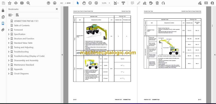