The Komatsu GD705-5 Motor Grader is a production grader used for road building, snow work, and heavy maintenance grading. Folks who reach for the Komatsu GD705-5 Motor Grader Shop Manual (SEN06489-11) are usually shop mechanics, field techs, or serious owner-operators. They’re trying to sort hard faults, rebuild major components, and stop repeat failures, not just top off fluids. This is the book you have open when the machine is down and the clock is ticking.
What this manual helps you do
- Trace hydraulic issues in the steering, blade, and auxiliary circuits using the kind of diagnostic steps and schematics you’d expect in a true shop manual.
- Diagnose engine, transmission, and driveline problems on the GD705-5, from no-move conditions to slipping, harsh shifts, or odd noises under load.
- Follow teardown and reassembly procedures for major components like cylinders, valves, axles, and powertrain assemblies so parts go back in the right order and orientation.
- Check and adjust linkages, brakes, articulation, and blade controls to bring a tired grader back into spec and stop premature wear.
- Verify electrical faults using wiring diagrams and step‑by‑step checks instead of just throwing parts at warning lights or intermittent shut‑downs.
Who this is for
This is aimed at field techs, dealership or independent shop mechanics, and fleet maintenance managers who do real repairs in-house. If you’re just running the machine and want daily checks and basic service, you’re better off with the Operation & Maintenance manual, not this shop manual.
FAQ
Q: Is this a PDF I can download and search?
A: Yes, it’s a PDF you can download, search by keyword, and print the pages you want for the job.
Q: Does it actually go deep enough for full overhauls?
A: Yes, the Komatsu GD705-5 Motor Grader Shop Manual walks through diagnostic procedures, disassembly sequences, and workshop-level repair steps for this model.
Q: How do I know if it matches my exact GD705-5 machine?
A: This manual is for the GD705-5 series; you should match your model designation and use the SEN06489-11 reference against your dealer or existing paperwork if you’re unsure.
Bottom line: If you’re turning wrenches on a GD705-5 and doing more than oil changes, this is the right manual. If you only need operating tips and service intervals, keep looking for the O&M book instead.
📘 Show Index
Table of Contents:
- 00 Index and foreword
- Foreword and general information
- Safety notice
- How to read the shop manual
- Explanation of terms for maintenance standard
- Handling of electric equipment and hydraulic components
- Handling of connectors newly used for engines
- How to read electric wire code
- Precautions when carrying out work
- Method of disassembling and connecting push-pull type coupler
- Standard tightening torque table
- List of Abbreviation
- Conversion table
- 01 Specification
- Specification drawing
- Specifications
- Weight table
- Table of fuel, coolant and lubricants
- 10 Structure and function
- Engine and cooling system
- Cooling system
- Cooling fan motor
- Power train system
- Power train system drawing
- Power train piping drawing
- Transmission control
- Torque converter
- Transmission
- Transmission control valve
- ECMV
- Main relief and torque converter relief valve
- Front axle
- Final drive
- Differential
- Differential lock solenoid valve
- Tandem drive
- Steering system
- Steering piping diagram
- Priority valve
- Steering valve
- Brake system
- Brake hydraulic piping diagram
- Brake valve
- Slack adjuster
- Accumulator (for brake)
- Charge valve
- Wheel brake
- Parking brake and bank control valve
- Parking brake
- Undercarriage and frame
- Hydraulic system
- Hydraulic system
- Work equipment hydraulic component layout
- Work equipment control
- Hydraulic tank
- Main pump
- Power train pump
- Control valve
- CLSS
- Functions and operation by valve
- Swivel joint
- Pilot check valve
- Separately installed safety valve
- Accumulator (for blade)
- Work equipment
- Circle and drawbar
- Blade
- Lifter
- Circle rotation motor
- Circle rotation gear
- Cab
- Electrical system
- Machine monitor
- Automatic shift control system
- Transmission controller
- Engine controller
- KOMTRAX system
- Starting engine circuit
- Stopping engine circuit
- Preheating circuit
- Engine power mode select circuit
- Cooling fan control function
- Sensor
- 20 Standard value table
- Standard value table
- Standard value table for engine
- Standard value table for machine
- Machine posture and procedure for measuring performance
- 30 Testing and adjusting
- Precautions before work
- Related information on testing and adjusting
- Tools for testing and adjusting
- Sketch of tools for testing and adjusting
- Engine and cooling system
- Testing engine speed
- Testing boost pressure
- Testing exhaust gas temperature
- Testing exhaust gas color
- Testing and adjusting valve clearance
- Testing compression pressure
- Testing blowby pressure
- Testing engine oil pressure
- Handling equipment of fuel system devices
- Releasing remaining pressure from fuel system
- Testing fuel pressure
- Testing fuel return rate and leakage
- Bleeding air from fuel circuit
- Testing fuel circuit for leakage
- Handling cylinder cutout mode operation
- Handling no-injection cranking operation
- Testing muffler (main body) and stuck muffler for looseness and damage
- Testing muffler function
- Testing installed condition of cylinder heads and manifolds
- Testing of engine piping for damage and looseness
- Testing and adjusting air conditioner compressor belt tension
- Replacing alternator belt
- Checking and replacing auto-tensioner
- Power train
- Testing power train oil pressure
- Adjusting transmission speed sensor
- Retrieval of disabled machine due to transmission valve failure
- Flushing procedure for torque converter and transmission circuits
- Testing and adjusting toe-in
- Adjusting bearing preload
- Testing and adjusting differential lock oil pressure
- Steering system
- Testing and adjusting steering oil pressure
- Testing oil leakage of steering cylinder
- Bleeding air from steering circuit
- Brake system
- Testing and adjusting brake oil pressure
- Releasing remaining pressure from brake circuit
- Bleeding air from brake circuit
- Testing wear of wheel brake disc
- Testing and adjusting parking brake
- Parking brake emergency releasing procedure
- Procedure for charging brake accumulator with nitrogen gas
- Hydraulic system
- Testing and adjusting work equipment oil pressure
- Testing and adjusting pump LS differential pressure
- Testing lift arm lock cylinder circuit oil pressure
- Testing oil leakage of work equipment cylinder
- Bleeding air from work equipment circuit
- Testing cooling fan pump circuit oil pressure
- Work equipment system
- Adjusting drawbar ball joint clearance
- Testing and adjusting circle guide clearance
- Adjusting circle rotation gear
- Procedure for charging blade accumulator with nitrogen gas
- Electrical system
- Special functions of machine monitor
- KOMTRAX terminal start-up procedure (ORBCOMM)
- Lamp indication of KOMTRAX terminal (ORBCOMM)
- KOMTRAX terminal start-up procedure (GPRS)
- Lamp indication of KOMTRAX terminal (GPRS)
- Handling voltage circuit of engine controller
- Testing diodes
- Pm Clinic
- 40 Troubleshooting
- Precautions before work
- General information on troubleshooting
- Points to remember when troubleshooting
- Sequence of events in troubleshooting
- Checks before troubleshooting
- Preparation work for troubleshooting of electrical system
- Classification and procedures for troubleshooting
- Failure codes table
- Failure and troubleshooting numbers
- Information in troubleshooting table
- Troubleshooting method for open circuit in wiring harness of pressure sensor system
- Connector list and layout
- Connection table for connector pin numbers
- T- branch box and T- branch adapter table
- Locations of fuses
- Troubleshooting by failure code
- Failure code [1500L0] TORQFLOW transmission: Double engagement
- Failure code [15G0MW] Transmission R clutch: Slip
- Failure code [15H0MW] Transmission FH clutch: Slip
- Failure code [15J0MW] Transmission FL clutch: Slip
- Failure code [15K0MW] Transmission 1st clutch: Slip
- Failure code [15L0MW] Transmission 2nd clutch: Slip
- Failure code [15M0MW] Transmission 3rd speed clutch: Slip
- Failure code [15N0MW] Transmission 4th clutch: Slip
- Failure code [15SBL1] ECMV R clutch: Fill signal is ON when command signal is OFF
- Failure code [15SBMA] ECMV R clutch: Malfunction
- Failure code [15SCL1] ECMV FH clutch: Fill signal is ON when command signal is OFF
- Failure code [15SCMA] ECMV FH clutch: Malfunction
- Failure code [15SDL1] ECMV FL clutch: Fill signal is ON when command signal is OFF
- Failure code [15SDMA] ECMV FL clutch: Malfunction
- Failure code [15SEL1] ECMV 1st clutch: Fill signal is ON when command signal is OFF
- Failure code [15SEMA] ECMV 1st clutch: Malfunction
- Failure code [15SFL1] ECMV 2nd clutch: Fill signal is ON when command signal is OFF
- Failure code [15SFMA] ECMV 2nd clutch: Malfunction
- Failure code [15SGL1] ECMV 3rd clutch: Fill signal is ON when command signal is OFF
- Failure code [15SGMA] ECMV 3rd clutch: Malfunction
- Failure code [15SHL1] ECMV 4th clutch: Fill signal is ON when command signal is OFF
- Failure code [15SHMA] ECMV 4th clutch: Malfunction
- Failure code [15SJMA] ECMV lockup clutch: Malfunction
- Failure code [15U0NT] Inching clutch: Overheating
- Failure code [2G42ZG] Front accumulater: Oil pressure drop
- Failure code [2G43ZG] Rear accumulater: Pressure drop
- Failure code [AA1ANX] Air cleaner: Clogging
- Failure code [AB00L6] Alternator; Engine start and stop signals are not matched.
- Failure code [AB00MA] Alternator: Malfunction
- Failure code: [B@BAZG] Derating in speed due to engine oil pressure drop
- Failure code: [B@BCNS] Engine coolant overheat
- Failure code [B@BEBF] Water in fuel error
- Failure code: [B@CENS] Torque converter oil overheat
- Failure code: [B@CKNS] Differential case: Overheat
- Failure code: [B@HANS] Hydraulic oil: Overheating
- Failure code [CA111] Engine controller internal error
- Failure code [CA115] Engine Ne, Bkup speed sensor error
- Failure code [CA122] Charge pressure sensor high error
- Failure code [CA123] Charge pressure sensor low error
- Failure code [CA131] Throttle sensor high error
- Failure code [CA132] Throttle sensor low error
- Failure code [CA144] Coolant sensor high error
- Failure code [CA145] Coolant sensor low error
- Failure code [CA153] Charge temperature sensor high error
- Failure code [CA154] Charge temperature sensor low error
- Failure code [CA155] Speed derating error by high charge temperature
- Failure code [CA187] Sensor power supply 2 low error
- Failure code [CA221] Atmospheric pressure sensor high error
- Failure code [CA222] Atmospheric pressure sensor low error
- Failure code [CA227] Sensor power supply 2 high error
- Failure code [CA234] Engine overspeed
- Failure code [CA238] Ne speed sensor power supply error
- Failure code [CA271] IMV/IMA: Short circuit
- Failure code [CA272] IMV/IMA open circuit
- Failure code [CA281] Abnormal supply pump pressure balance
- Failure code [CA322] Injector #1 (L#1) open/short
- Failure code [CA323] Injector #5 (L#5) open/short
- Failure code [CA324] Injector #3 (L#3) open/short
- Failure code [CA325] Injector #6 (L#6) open/short
- Failure code [CA331] Injector #2 (L#2) open/short
- Failure code [CA332] Injector #4 (L#4) open/short
- Failure code [CA342] Data compatibility error in engine controller
- Failure code [CA351] Injector drive circuit error
- Failure code [CA352] Sensor power supply 1 low error
- Failure code [CA386] Sensor power supply 1 high error
- Failure code [CA428] Water-in-fuel sensor high error
- Failure code [CA429] Water-in-fuel sensor low error
- Failure code [CA431] Idle validation switch error
- Failure code [CA432] Idle validation action error
- Failure code [CA435] Engine oil pressure switch error
- Failure code [CA441] Power supply voltage low error
- Failure code [CA442] Power supply voltage high error
- Failure code [CA449] Common rail pressure high error 2
- Failure code [CA451] Common rail pressure sensor high error
- Failure code [CA452] Common rail pressure sensor low error
- Failure code [CA488] Torque derating error by high charge temperature
- Failure code [CA553] Common rail pressure high error 1
- Failure code [CA559] Rail Press Low Error
- Failure code [CA689] Eng Ne Speed Sensor Error
- Failure code [CA731] Eng Bkup Speed Sens Phase Error
- Failure code [CA757] All continuous data lost error
- Failure code [CA778] Eng Bkup Speed Sensor Error
- Failure code [CA1633] KOMNET (CAN communication) error
- Failure code [CA2185] Throttle sensor power supply high error
- Failure code [CA2186] Throttle sensor power supply low error
- Failure code [CA2249] Supply pump pressure low error 2
- Failure code [CA2265] Fuel Feed Pump Open Error
- Failure code [CA2266] Fuel Feed Pump Short Error
- Failure code [CA2311] Abnormality in IMV (IMA) solenoid
- Failure code [CA2555] Intake heater relay open circuit
- Failure code [CA2556] Intake heater relay short circuit
- Failure code [D160KA] Backup lamp relay: Open circuit, hot short circuit in wiring harness
- Failure code [D160KB] Backup lamp relay: Ground fault
- Failure code [D19KKZ] Differential lock relay: Open circuit, ground fault
- Failure code [D5ZHL6] C terminal signal: Signal does not match to actual engine state
- Failure code [DAFRKR] CAN communication failure (monitor panel)
- Failure code [DAQ0KK] Transmission controller: Power supply voltage low error (input)
- Failure code [DAQOKT] Transmission controller: Non-volatile memory error
- Failure code [DAQ2KK] Transmission controller load power line: Power supply voltage drop (input)
- Failure code [DAQ9KQ] Transmission controller model selection: Model selection signal disagreement
- Failure code [DAQRKR] Transmission controller CAN communication: Communication error
- Failure code [DAQRMA] Transmission controller option setting: Malfunction
- Failure code [DB2RKR] Engine controller CAN communication: Communication error
- Failure code [DD1PKB] RPM set switch power supply short circuit
- Failure code [DD1QKB] RPM set mode switch short circuit
- Failure code [DDB6L4] Transmission gearshift lever: Parking brake signal error
- Failure code [DDTHKA] Fill switch for FH clutch: Open circuit
- Failure code [DDTJKA] Fill switch for FL clutch: Open circuit
- Failure code [DDTKKA] Fill switch for 1st clutch: Open circuit
- Failure code [DDTLKA] Fill switch for 2nd clutch: Open circuit
- Failure code [DDTMKA] Fill switch for 3rd clutch: Open circuit
- Failure code [DDTNKA] Fill switch for R clutch: Open circuit
- Failure code [DDTPKA] Fill switch for 4th clutch: Open circuit
- Failure code [DF10KA] Transmission gearshift lever: No gear speed signal is input
- Failure code [DF10L4] Transmission gearshift lever: Gear speed/travel direction signal error
- Failure code [DGF1KX] Transmission oil temperature sensor: Input signal out of range
- Failure code [DGH2KB] Hydraulic oil temperature sensor: Ground fault
- Failure code [DGT1KX] Torque converter oil temperature sensor: Input signal out of range
- Failure code [DGT7KB] Differential oil temperature sensor: Ground fault
- Failure code [DHT5KX] Out of Range of T/C Input Pressure Sensor
- Failure code [DHT5L6] Failure of T/C Oil Press Sensor
- Failure code [DJF1KA] Fuel level sensor: Open circuit
- Failure code [DK70KX] Inching pedal angle sensor: Input signal out of range
- Failure code [DKD0KX] Articulation angle sensor: Input signal out of range
- Failure code [DLF1KA] Transmission input shaft speed sensor: Open circuit
- Failure code [DLF1LC] Transmission input shaft speed sensor: Speed signal does not match
- Failure code [DLF2KA] Transmission intermediate shaft speed sensor: Open circuit
- Failure code [DLF2LC] Transmission intermediate shaft speed sensor: Speed signal does not match
- Failure code [DLM3KA] Fan speed sensor: Open circuit
- Failure code [DLM3LC] Fan speed sensor: Short circuit
- Failure code [DLM3MB] Radiator Fan Control Mismatch
- Failure code [DLT3KA] Transmission output shaft speed sensor: Open circuit
- Failure code [DV00KB] Buzzer: Short circuit
- Failure code [DW4BKA] Parking brake solenoid valve: Open circuit
- Failure code [DW4BKB] Parking brake solenoid valve: Short circuit
- Failure code [DX16KA] Fan motor EPC solenoid: Open circuit
- Failure code [DX16KB] Fan motor EPC solenoid: Short circuit
- Failure code [DX16KY] Fan motor EPC solenoid: Short circuit to power supply line
- Failure code [DXH1KA] Lockup ECMV solenoid: Open circuit
- Failure code [DXH1KB] Lockup ECMV solenoid: Short circuit
- Failure code [DXH1KY] Lockup ECMV solenoid: Short circuit to power supply line
- Failure code [DXH2KA] FH clutch ECMV solenoid: Open circuit
- Failure code [DXH2KB] FH clutch ECMV solenoid: Short circuit
- Failure code [DXH2KY] FH clutch ECMV solenoid: Short circuit to power supply line
- Failure code [DXH3KA] FL clutch ECMV solenoid: Open circuit
- Failure code [DXH3KB] FL clutch ECMV solenoid: Short circuit
- Failure code [DXH3KY] FL clutch ECMV solenoid: Short circuit to power supply line
- Failure code [DXH4KA] 1st clutch ECMV solenoid: Open circuit
- Failure code [DXH4KB] 1st clutch ECMV solenoid: Short circuit
- Failure code [DXH4KY] 1st clutch ECMV solenoid: Short circuit to power supply line
- Failure code [DXH5KA] 2nd clutch ECMV solenoid: Open circuit
- Failure code [DXH5KB] 2nd clutch ECMV solenoid: Short circuit
- Failure code [DXH5KY] 2nd clutch ECMV solenoid: Short circuit to power supply line
- Failure code [DXH6KA] 3rd clutch ECMV solenoid: Open circuit
- Failure code [DXH6KB] 3rd clutch ECMV solenoid: Short circuit
- Failure code [DXH6KY] 3rd clutch ECMV solenoid: Short circuit to power supply line
- Failure code [DXH7KA] R clutch ECMV solenoid: Open circuit
- Failure code [DXH7KB] R clutch ECMV solenoid: Short circuit
- Failure code [DXH7KY] R clutch ECMV solenoid: Short circuit to power supply line
- Failure code [DXHHKA] 4th clutch ECMV solenoid: Open circuit
- Failure code [DXHHKB] 4th clutch ECMV solenoid: Short circuit
- Failure code [DXHHKY] 4th clutch ECMV solenoid: Short circuit to power supply line
- Troubleshooting of electrical system (E-mode)
- E-1 Engine does not start (Starting motor does not turn)
- E-2 Preheating does not work
- E-3 When starting switch is turned to ON position, machine monitor displays nothing
- E-4 When starting switch is turned to ON position, machine monitor does not reach standard screen
- E-5 When starting switch is turned to ON position, caution monitor flashes or lights up, or machine monitor does not display correct screen
- E-6 Emergency stop monitor lights up while engine is running
- E-7 Speedometer or engine tachometer does not indicate correctly
- E-8 Engine coolant temperature gauge does not indicate correctly
- E-9 Articulation angle indicator does not indicate correctly
- E-10 Torque converter oil temperature gauge does not indicate correctly
- E-11 Fuel level gauge does not indicate correctly
- E-12 Character display does not display correctly
- E-13 Centralized warning lamp does not light up or does not go off
- E-14 Alarm buzzer does not sound or does not stop sounding
- E-15 Machine monitor mode selector switch does not work
- E-16 Transmission mode does not switch
- E-17 Engine mode does not switch
- E-18 Differential lock function does not work or cannot be reset [for machine with differential lock specification]
- E-19 Lift arm lock pin does not lock lift arm or does not unlock it [for machine with lift arm specification]
- E-20 Blade accumulator function does not work or is not reset [for machine with blade accumulator specification]
- E-21 Horn does not sound or does not stop sounding
- E-22 Backup alarm does not sound or does not stop sounding
- E-23 Headlamp, clearance lamp and tail lamp do not light up or do not go off
- E-24 Working lamp does not light up or does not go off
- E-25 Fog lamp does not light up or does not go off
- E-26 Turn signal lamp and hazard lamp do not flash.
- E-27 Stop lamp does not light up or does not go off
- E-28 Backup lamp does not light up or does not go off
- E-29 Windshield wiper does not operate
- E-30 Window washer does not operate
- E-31 KOMTRAX system does not operate correctly
- Troubleshooting for hydraulic and mechanical system (H-mode)
- Information described in troubleshooting table (H-mode)
- H-1 Engine speed drops significantly or engine stalls
- H-2 Machine does not move off (both forward and reverse)
- H-3 Gear speed does not shift
- H-4 Travel speed or power is low
- H-5 Torque converter lockup does not operate or is not canceled
- H-6 Machine starts or gear speed shifts with long time lag
- H-7 Torque converter oil temperature is high
- H-8 Differential lock function does not operate or is not canceled
- H-9 Steering speed or power is insufficient
- H-10 Steering wheel does not move
- H-11 Wheel brakes do not work or are weak
- H-12 Wheel brakes are not released or drag
- H-13 Parking brake does not work or it is weak
- H-14 Parking brake (including emergency release system) is not released or drags
- H-15 All work equipment operates slowly or lacks power
- H-16 All work equipments do not operate
- H-17 Unusual noise is heard from around hydraulic pump
- H-18 Blade lift speed or power is low
- H-19 Hydraulic drift of lifted blade is large
- H-20 Drawbar side shift speed or power is low
- H-21 Blade cross slide speed or power is low
- H-22 Power tilt speed or power is low
- H-23 Articulate speed or power is low
- H-24 Leaning speed or power is insufficient
- H-25 Hydraulic drift (tilting) of leaning is large
- H-26 Blade does not rotate
- H-27 Lift arm lock pin is not locked or is not canceled
- H-28 Blade accumulator does not operate or is not canceled [blade accumulator specifications]
- H-29 Fan rotation is abnormal (such as excessive noise or vibration of fan, or overheating)
- H-30 Unusual noise is heard from around fan
- Troubleshooting of engine (S-mode)
- Method of using troubleshooting charts
- S-1 Starting performance is poor.
- S-2 Engine does not start
- S-3 Engine does not pick up smoothly
- S-4 Engine stops during operations
- S-5 Engine does not rotate smoothly
- S-6 Engine lacks output (or lacks power)
- S-7 Exhaust smoke is black (incomplete combustion)
- S-8 Oil consumption is excessive (or exhaust smoke is blue)
- S-9 Oil becomes contaminated quickly
- S-10 Fuel consumption is excessive
- S-11 Oil is in coolant (or coolant spurts back, or coolant level goes down)
- S-12 Oil pressure drops
- S-13 Oil level rises (water, fuel in oil)
- S-14 Coolant temperature becomes too high (overheating)
- S-15 Abnormal noise is made
- S-16 Vibration is excessive
- Shop Manual
- 50 Disassembly and assembly
- Precautions before work
- Related information on disassembly and assembly
- How to read this manual
- Coating materials list
- Special tools list
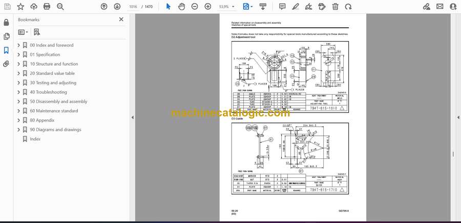
- Sketches of special tools
- Engine and cooling system
- Removal and installation of fuel supply pump assembly
- Removal and installation of fuel injector assembly
- Removal and installation of cylinder head assembly
- Removal and installation of engine front oil seal assembly
- Removal and installation of engine rear oil seal assembly
- Removal and installation of cooling fan pump assembly
- Removal and installation of cooling fan and fan motor assembly
- Removal and installation of radiator assembly
- Removal and installation of aftercooler assembly
- Removal and installation of power train oil cooler assembly
- Removal and installation of fuel tank assembly
- Removal and installation of engine hood assembly
- Power train
- Removal and installation of engine and transmission assembly
- Disconnection and connection of transmission and torque converter assembly from/to engine
- Disassembly and assembly of transmission assembly
- Disassembly and assembly of torque converter assembly
- Removal and installation of tandem drive and final drive assembly
- Disassembly and assembly of tandem drive assembly
- Disassembly and assembly of final drive assembly
- Steering system
- Removal and installation of steering valve (Orbitrol) assembly
- Brake system
- Disassembly and assembly of wheel brake assembly
- Undercarriage and frame
- Removal and installation of center hinge pin
- Hydraulic system
- Removal and installation of hydraulic tank, battery and frame assembly
- Removal and installation of hydraulic tank assembly
- Removal and installation of control valve assembly
- Disassembly and assembly of control valve assembly
- Disassembly and assembly of hydraulic cylinder assembly
- Work equipment
- Removal and installation of blade assembly
- Disassembly and assembly of circle drawbar assembly
- Removal and installation of circle rotation gear assembly
- Disassembly and assembly of circle rotation gear assembly
- Removal and installation of ripper assembly
- Cab and its attachments
- Removal and installation of operator's cab assembly
- Removal and installation of floor frame assembly
- Removal and installation of operator's cab glass (adhered window glass)
- Removal and installation of air conditioner unit assembly
- Electrical system
- Removal and installation of engine controller assembly
- Removal and installation of starting motor
- Removal and installation of battery
- Removal and installation of machine monitor assembly
- Removal and installation of transmission controller assembly
- Removal and installation of KOMTRAX terminal assembly (ORBCOMM)
- Removal and installation of KOMTRAX terminal assembly (GPRS)
- 60 Maintenance standard
- Engine and cooling system
- Engine mount and transmission mount
- Cooling system
- Cooling fan motor
- Power train system
- Torque converter
- Transmission
- Transmission control valve
- ECMV
- Main relief valve and torque converter relief valve
- Front axle
- Final drive
- Differential
- Tandem drive
- Brake system
- Slack adjuster
- Wheel brake
- Parking brake
- Undercarriage and frame
- Hydraulic system
- Main pump
- Power train pump
- Control valve
- Hydraulic cylinder
- Work equipment
- Circle and drawbar
- Blade
- Lifter
- Circle rotation gear
- 80 Appendix
- Precautions before work
- Air conditioner
- Precautions for refrigerant
- Air conditioner components
- Structure and function of refrigeration system
- Overview of refrigeration system
- Air conditioner unit
- Compressor
- Condenser
- Receiver drier
- Air conditioner control panel
- Procedure for check and troubleshooting
- Circuit diagram and layout of connector pins
- System diagram
- Detail of air conditioner unit
- Parts and connectors layout
- Testing air leakage (ducts)
- Check with self-diagnosis (control panel display)
- Testing temperature control
- Testing Fresh/Recirc air changeover
- Testing evaporator temperature sensor
- Testing relays
- Testing blower amp
- Troubleshooting Chart 1
- Troubleshooting Chart 2
- Information in troubleshooting table
- Troubleshooting for power supply system (Air conditioner does not operate)
- Troubleshooting of compressor and refrigerant system (Air is not cooled)
- Troubleshooting for blower motor system (Air does not come out or air flow is improper)
- Troubleshooting for temperature control
- Troubleshooting for FRESH/RECIRC air changeover
- Troubleshooting with gauge pressure
- Connection of service tool
- Precautions for disconnecting and connecting air conditioner piping
- Handling compressor oil
- 90 Diagrams and drawings
- Hydraulic diagrams and drawings
- Symbols used in hydraulic circuit diagrams
- Hydraulic circuit diagram
- Electrical diagrams and drawings
- Symbols used in electric circuit diagrams
- Electrical circuit diagram
- Index
Komatsu


