The Komatsu WA1200-6 Wheel Loader Shop Manual (SEN06774-16) is meant for doing real repair work on a large production loader, not just daily checks. This kind of machine is usually in mining or big quarry operations where every hour down costs real money. People who reach for this manual are usually shop mechanics, field techs, or contractors who actually tear into systems, not just run the machine. They’re trying to diagnose faults, strip components, and put them back together without guesswork.
What this manual helps you do
- Trace hydraulic issues on the WA1200-6 by following circuit layouts and typical test points for the loader’s multiple pump system.
- Diagnose electrical faults using wiring information, connector locations, and guided troubleshooting logic for the machine’s control systems.
- Follow disassembly and reassembly procedures for major components like the powertrain, axles, and main structures using standard workshop tools.
- Check adjustment procedures for linkages, brakes, steering, and other systems so the loader goes back into service correctly set up.
- Handle engine, cooling, and driveline service at workshop level, beyond what an operation and maintenance manual would cover.
Who this is for
This shop manual suits a field technician, shop mechanic, or fleet maintenance lead who’s responsible for full repairs on a Komatsu WA1200-6. If you only need basic operation, greasing points, and interval charts, you’re better off with the Operation and Maintenance Manual, not this one.
FAQ
Q: Is this a searchable PDF I can download and print?
A: Yes, it’s a PDF you can download, search by keyword, and print specific sections for use in the shop or in the field.
Q: Does it go deep enough for full overhauls?
A: Yes, the Komatsu WA1200-6 Wheel Loader Shop Manual walks through diagnostic procedures, disassembly sequences, and workshop-level repair guidance. It’s what most shops use when they’re rebuilding or troubleshooting major systems.
Q: How do I know if it matches my machine’s serial number or variant?
A: Check your loader’s serial plate and compare it to the SEN06774-16 reference in your Komatsu documentation or with your dealer; they can confirm if this is the correct shop manual for your specific unit.
Bottom line: If you’re the person actually fixing a WA1200-6, this is more or less the manual you need; if you’re just operating or doing light service, keep looking for the O&M book instead.
📘 Show Index
Table of Contents:
- 00 Index and foreword
- Table of Contents
- Foreword and general information
- Safety notice
- How to read the shop manual
- Explanation of terms for maintenance standard
- Handling of hydraulic components
- Method of disconnecting and connecting push-pull type coupler
- Handling of electric equipment
- How to read electric wire code
- Precautions when performing work
- Standard tightening torque table
- List of abbreviation
- Conversion table
- 01 Specification
- Contents
- Specification
- Specification dimension drawing
- Specifications
- Weight table
- Table of fuel, coolant and lubricants
- 10 Structure and function
- Contents
- Engine and cooling system
- Damper
- Cooling system
- Cooling fan motor
- Power train
- Power train
- Hydraulic piping drawing of torque converter and transmission
- Torque converter
- Main relief valve and torque converter relief valve
- Torque converter regulator valve
- ECMV
- Transmission
- Transmission control valve
- Transmission lubricating oil relief valve
- Transfer
- Torque converter oil cooler
- Center support
- Axle
- Final drive
- Steering system
- Steering equipment layout drawing
- AJSS
- Steering pump
- Switch pump
- Steering demand valve
- Rotary valve
- EPC valve (for steering)
- Diverter valve
- Emergency steering relief valve
- Steering lock valve
- Brake system
- Brake equipment layout drawing
- Brake valve
- Charge valve
- Accumulator (for brake)
- Slack adjuster
- Brake
- Parking brake
- Parking brake solenoid valve
- Emergency parking brake release valve
- Check valve of parking brake circuit
- Undercarriage and frame
- Axle mount
- Center hinge pin
- Jack-up point
- Hydraulic system
- Hydraulic piping layout drawing
- Work equipment control lever linkage
- Hydraulic tank
- Work equipment pump No.1
- Work equipment pump No.2
- EPC valve (for work equipment)
- Neutral cutoff solenoid valve (NC valve)
- Relief valve
- Accumulator (for EPC valve)
- Work equipment control valve
- Work equipment
- Electrical system
- Machine monitor system
- Multi-function monitor
- Work equipment and AJSS control system
- Work equipment control lever
- Transmission control system
- Engine starting circuit
- Engine stopping circuit
- Electric parking brake control
- Sensor
- 20 Standard value table
- Contents
- Standard value table
- Standard value table for engine
- Standard value table for chassis
- 30 Testing and adjusting
- Contents
- Precautions Before Work
- Tool for testing, adjusting and troubleshooting
- Tools for testing, adjusting, and troubleshooting
- Safety precautions to follow before starting work
- Engine and cooling system
- Testing engine speed
- Testing exhaust gas color
- Testing blow-by pressure
- Measuring engine oil pressure
- Measuring exhaust gas temperature
- Testing intake air pressure (boost pressure)
- Testing radiator performance
- Measuring wind speed across radiator and oil cooler
- Testing and adjusting fan belt tension
- Testing and adjusting air conditioner compressor belt tension
- Power train
- Adjusting speed sensor
- Testing and adjusting torque converter and transmission oil pressure
- Traction control function checking procedure
- Testing torque converter oil cooler performance
- Testing additional cooler fan speed
- Flushing procedure for torque converter and transmission circuit
- Retrieval of disabled machine due to transmission valve failure
- How to measure play of center hinge bearing
- Measuring wear of rear axle support
- Steering system
- Testing and adjusting steering oil pressure
- Testing and adjusting emergency steering oil pressure
- Bleeding air from steering circuit
- Testing and adjusting steering stopper bolt
- Adjusting steering follow-up linkage
- Testing steering EPC valve
- Testing and adjusting steering surge cut valve oil pressure
- Testing and adjusting steering main relief valve oil pressure
- Testing rotary valve output pressure
- Brake system
- Testing brake performance
- Testing lowering of wheel brake oil pressure
- Testing of slack adjuster
- Measuring wear of wheel brake disc
- Testing and adjusting accumulator charge pressure
- Testing brake accumulator oil pressure leakage
- Testing emergency parking brake valve oil leakage amount
- Testing brake valve oil leakage amount
- Testing brake cooling oil pressure
- Testing brake oil cooler performance
- Testing parking brake performance
- Testing wear of parking brake disc
- Method of releasing parking brake manually
- Testing parking brake oil pressure
- Testing of accumulator nitrogen gas pressure and procedure for charging accumulator with nitrogen gas
- Hydraulic system
- Testing and adjusting work equipment oil pressure by using multi monitor
- Testing and adjusting work equipment oil pressure by using oil pressure gauge
- Testing and adjusting work equipment PPC oil pressure
- Measuring point of hydraulic pump oil pressure
- Testing and adjusting PV control relief valve oil pressure
- Testing and adjusting differential valve output oil pressure
- Testing work pump ES valve output pressure
- Testing and adjusting work pump CO (cut-off) valve oil pressure
- Testing and adjusting work equipment pump TVC valve oil pressure
- Operation test of work equipment valve by work equipment speed (speed of work equipment is low)
- Testing hydraulic oil cooler performance
- Bleeding air from hydraulic circuit
- Releasing remaining pressure in hydraulic circuit
- Work equipment
- Checking center hinge pin lubrication
- Adjustment method of auto grease injector delivery
- Setting method of auto grease timer
- Electrical system
- Testing and adjusting bucket proximity switch
- Adjusting lift arm potentiometer
- Initial setting procedure for remote boom positioner (origin input method)
- Checking proximity switch operation pilot lamp
- Adjusting AJSS lever angle sensor and frame angle sensor
- Testing and adjusting potentiometer mounting position
- Procedure for testing diodes
- Basic precautions for KOMTRAX Plus controller
- Inspection and maintenance of KOMTRAX Plus controller
- Initial setting procedure for KOMTRAX Plus controller
- Precautions for replacing KOMTRAX Plus controller
- Measurement procedure by downloading data in KOMTRAX Plus controller
- Measurement procedure by multi monitor
- Special functions of multi monitor
- Pm Clinic
- Outline of measurement procedure for Pm Clinic
- Preparation for measurement for Pm Clinic
- Pm clinic service
- 40 Troubleshooting
- Contents
- Precautions Before Work
- General information on troubleshooting
- Symptom and troubleshooting numbers
- Sequence of events in troubleshooting
- Check before troubleshooting
- Classification and procedures of troubleshooting
- Breakage of hydraulic cylinder
- Failure codes table
- Symptom and troubleshooting numbers
- Information in troubleshooting table
- Troubleshooting method for open circuit in wiring harness of pressure sensor system
- Layout drawing of connector pins
- Connector list and layout
- T- branch box and T- branch adapter table
- Table of fuse locations
- Troubleshooting by failure code
- Failure code [1500L0] Double Engagement of Transmission Clutches
- Failure code [1540N1] T/M overrun
- Failure code [15B0NX] T/M Oil Filter Clogged
- Failure code [15SAL1] ECMV (F) Fill Switch Short Circuit
- Failure code [15SALH] ECMV (F) Fill Switch circuit Disconnect
- Failure code [15SBL1] ECMV (R) Fill Switch Short Circuit
- Failure code [15SBLH] ECMV (R) Fill Switch circuit Disconnect
- Failure code [15SEL1] ECMV (1) Fill Switch Short Circuit
- Failure code [15SELH] ECMV (1) Fill Switch circuit Disconnect
- Failure code [15SFL1] ECMV (2) Fill Switch Short Circuit
- Failure code [15SFLH] ECMV (2) Fill Switch circuit Disconnect
- Failure code [15SGL1] ECMV (3) Fill Switch Short Circuit
- Failure code [15SGLH] ECMV (3) Fill Switch circuit Disconnect
- Failure code [2F00MA] Parking brake circuit failure
- Failure code [2G42ZG] Accumulator Oil Press. F Low
- Failure code [2G43ZG] Accumulator Oil Press. R Low
- Failure code [44K0L4] Bucket cylinder position detector SW failure
- Failure code [7REAKA] ACC Signal Malfunction
- Failure code [989P00] Direction protection warning
- Failure code [989Q00] Work equipment protection
- Failure code [989R00] Tire slip
- Failure code [989S00] Parking Brake Dragging
- Failure code [989T00] Stationary steering (Brake: OFF, Load: OFF)
- Failure code [989U00] Stationary steering (Brake: OFF, Load: ON)
- Failure code [989V00] Stationary steering (Brake: ON, Load: OFF)
- Failure code [989W00] Stationary steering (Brake: ON, Load: ON)
- Failure code [AA1ANX] Air Cleaner 1 Clogging
- Failure code [AA1BNX] Air Cleaner 2 Clogging
- Failure code [AA1CNX] Air Cleaner 3 Clogging
- Failure code [AA1DNX] Air Cleaner 4 Clogging
- Failure code [AB00L6] Discharge of alternator R terminal
- Failure code [AB00MA] Discharge of alternator R terminal
- Failure code [AB00MB] Discharge of alternator R terminal
- Failure code [B@BCZK] Drop in Engine Coolant Level
- Failure code [b@C5ZK] Low brake fluid level (before engine start)
- Failure code [B@C5ZK] Low brake fluid level (while engine is running)
- Failure code [B@C6NS] High brake oil temp.
- Failure code [b@CENS] High torque converter oil temp.
- Failure code [B@CENS] Very high torque converter oil temp.
- Failure code [B@GAZK] Low battery 1 fluid level
- Failure code [B@GBZK] Low battery 2 fluid level
- Failure code [B@GCZK] Low battery 3 fluid level
- Failure code [B@HANS] High hydraulic oil temp.
- Failure code [B@HAZK] Low hydraulic oil level
- Failure code [D191KA] Neutral Output Relay Disconnection
- Failure code [D191KB] Neutral Output Relay hot short
- Failure code [D19MKA] SW pump PNC solenoid Relay (Disconnect/Short Circuit)
- Failure code [D19MKY] SW pump PNC solenoid Relay hot short
- Failure code [D19MMA] SW pump PNC solenoid circuit 1 Failure
- Failure code [D19MMB] SW pump PNC solenoid circuit 2 Failure
- Failure code [D5ZHKA] Starting Switch C signal circuit (Disconnect/Short Circuit)
- Failure code [D5ZHKB] Starting Switch C signal circuit Hot short
- Failure code [D5ZHKZ] Starting Switch C signal circuit failure
- Failure code [D5ZHL6] Ignition C terminal Circuit Failure
- Failure code [DAF5KP] Monitor Panel 5 V source sys Error
- Failure code [DAFRKR] Communication Lost Monitor Panel Controller
- Failure code [DAQ0KK] Drop in Transmission Controller Main Power Source
- Failure code [DAQ0KT] Nonvolatile Memory (EEPROM) Abnormal
- Failure code [DAQ2KK] Drop in Transmission Controller Solenoid Power Source
- Failure code [DAQRKR] Communication Lost T/M Controller
- Failure code [DAQRMA] Defective Option Selection Data in Transmission
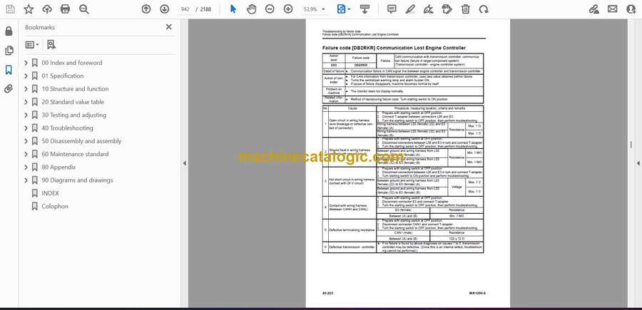
- Failure code [DB2RKR] Communication Lost Engine Controller
- Failure code [DB90KK] Drop in Work Controller Main Power Source
- Failure code [DB90KT] Nonvolatile Memory (EEPROM) Abnormal
- Failure code [DB92KK] Solenoid Voltage Failure (Work controller)
- Failure code [DB95KX] 5 V source sys Error (Work controller)
- Failure code [DB9RKR] Communication Lost Boom Bucket & Joy stick Controller
- Failure code [DB9RMA] Defective Option Selection Data in Boom Bucket Controller
- Failure code [DB9RMC] Communication Lost (Work Controller)
- Failure code [DBB0KK] VHMS source voltage Error
- Failure code [DBB0KQ] VHMS Connector Mismatch
- Failure code [DBB3KK] Abnormality in VBAT voltage (VHMS VBAT<10V)
- Failure code [DBB5KP] VHMS 5 V source sys Error
- Failure code [DBB6KP] VHMS 24 V source sys Error
- Failure code [DBB7KP] VHMS 12 V source sys Error
- Failure code [DBBQMC] Communication Lost (VHMS CAN0)
- Failure code [DBBRKR] Communication Lost VHMS Controller
- Failure code [DBBRMC] Communication Lost (VHMS CAN1)
- Failure code [DD10KX] Verification Mode SW Failure
- Failure code [DD1ALD] Remote positioner upper side set sw failure
- Failure code [DD1BLD] Remote positioner lower side set sw failure
- Failure code [DDA7L4] Throttle Lock Input signal Short Circuit
- Failure code [DDA8KB] Throttle Lock (set/accelerator) switch Short Circuit
- Failure code [DDA9KB] Throttle Lock (set/decelerator) switch Short Circuit
- Failure code [DDB6L4] Neutral Signal Malfunction
- Failure code [DDD7KA] Speed control dial circuit (Low Voltage)
- Failure code [DDD7KB] Speed control dial circuit (High Voltage)
- Failure code [DDDBKA] Traction control dial circuit (Low Voltage)
- Failure code [DDDBKB] Traction control dial circuit (High Voltage)
- Failure code [DDE5MA] Emergency steering signal Failure
- Failure code [DDK4KA] AJSS F/N/R Input Signal Disconnection
- Failure code [DDK4KB] AJSS F/N/R Input Signal Short Circuit
- Failure code [DDK5L4] Joystick Shift up/down SW circuit (Disconnect/Short Circuit)
- Failure code [DDP5KA] Steering lock detector pressure switch signal circuit Disconnect
- Failure code [DDT4LD] T/M Cut Off set switch signal short circuit
- Failure code [DDW9LD] Kickdown Switch Short Circuit
- Failure code [DGE5KX] Ambient air temp Sensor Failure
- Failure code [DGF1KA] Transmission Oil Temperature sensor signal Disconnect
- Failure code [DGF1KB] Abnormality in Transmission Oil Temperature sensor Short Circuit
- Failure code [DGF1KX] Transmission Oil Temperature sensor Failure (For Check)
- Failure code [DGH2KX] Hydraulic oil temp. sensor circuit failure
- Failure code [DGR2KA] Brake oil temp. sensor circuit Disconnection
- Failure code [DGR2KX] Brake oil temp. sensor circuit failure
- Failure code [DGT1KX] T/C oil temp. sensor circuit failure
- Failure code [DH20KX] Torque converter pressure sensor circuit
- Failure code [DH21KA] Loader pump oil press sensor (Disconnect/Short Circuit)
- Failure code [DH21KB] Loader pump oil press sensor hot short
- Failure code [DHPCKA] Boom bottom press. (Disconnect/Short Circuit)
- Failure code [DHPCKX] Boom bottom press. sensor circuit failure
- Failure code [DHPCKY] Boom bottom press. hot short
- Failure code [DHPDKX] Boom head press. sensor circuit failure
- Failure code [DHT1KX] T/M Cut Off pressure sensor signal Disconnect
- Failure code [DHT2L6] T/M oil filter sensor circuit failure
- Failure code [DHT3KX] Transmission main pressure sensor circuit
- Failure code [DHT4KX] Main PPC oil pressure sensor circuit
- Failure code [DHT5KX] Torque converter intake pressure sensor circuit
- Failure code [DHT8KX] Steering Oil Press. Sensor Failure
- Failure code [DHTAKX] Transmission lubrication pressure sensor circuit
- Failure code [DHTBKA] Modulation clutch pressure sensor circuit Disconnect
- Failure code [DHTBKB] Modulation clutch pressure sensor signal short circuit
- Failure code [DHU2KA] F Brake Oil press Sensor Disconnect
- Failure code [DHU2KB] F Brake Oil press Sensor Hot short
- Failure code [DHU2KX] F Brake Oil press Sensor Failure
- Failure code [DHU3KA] R Brake Oil press Sensor Disconnect
- Failure code [DHU3KB] R Brake Oil press Sensor Hot short
- Failure code [DHU3KX] R Brake Oil press Sensor Failure
- Failure code [DJF1KA] Fuel level sensor circuit Disconnection
- Failure code [DK30KA] Steering lever angle sensor (Disconnect/Short Circuit)
- Failure code [DK30KY] Steering lever angle sensor circuit hot short
- Failure code [DK59KA] Boom lever potentiometer (main) (Disconnect/Short Circuit)
- Failure code [DK59KY] Boom lever potentiometer (main) hot short
- Failure code [DK59L8] Boom lever potentiometer (main & sub) failure
- Failure code [DK5AKA] Boom lever potentiometer (sub) (Disconnect/Short Circuit)
- Failure code [DK5AKY] Boom lever potentiometer (sub) hot short
- Failure code [DK5BKA] Bucket lever potentiometer (main) (Disconnect/Short Circuit)
- Failure code [DK5BKY] Bucket lever potentiometer (main) hot short
- Failure code [DK5BL8] Bucket lever potentiometer (main & sub) failure
- Failure code [DK5CKA] Bucket lever potentiometer (sub) (Disconnect/Short Circuit)
- Failure code [DK5CKY] Bucket lever potentiometer (sub) hot short
- Failure code [DKA0KA] Boom angle sensor (Disconnect/Short Circuit)
- Failure code [DKA0KX] Boom angle sensor circuit failure
- Failure code [DKA0KY] Boom angle sensor circuit hot short
- Failure code [DKA0L0] Boom angle sensor failure
- Failure code [DKD0KA] Frame angle sensor (Disconnect/Short Circuit)
- Failure code [DKD0KY] Frame angle sensor circuit hot short
- Failure code [DKD0KZ] Frame and steering angle sensor failure
- Failure code [DKH0KA] Angle sensor circuit (FR) Disconnect
- Failure code [DKH0KB] Angle sensor circuit (FR) Hot short
- Failure code [DKH1KA] Angle sensor circuit (LR) Disconnect
- Failure code [DKH1KB] Angle sensor circuit (LR) Hot short
- Failure code [DLE2KA] Engine Speed Sensor Disconnection
- Failure code [DLE2LC] Engine Speed Sensor Short Circuit
- Failure code [DLF6LC] Tire speed sensor circuit
- Failure code [DLFAKA] Mod/c Output Speed Sensor Disconnect
- Failure code [DLFALC] Mod/c Output Speed Sensor Short Circuit
- Failure code [DLT4KB] Output Shaft Speed Sensor (1) Short Circuit
- Failure code [DLT4KX] Output Shaft Speed Sensor (1) Disconnection
- Failure code [DT20KB] Transmission cut off indicator Output short circuit
- Failure code [DT21KB] Speed Control indicator Output short circuit
- Failure code [DUM8KB] VHMS Operation lamp Short Circuit
- Failure code [DV00KY] Buzzer circuit hotshort (for usually)
- Failure code [DV01KY] Buzzer circuit hotshort (for special)
- Failure code [DW23KA] T/M E-POCV (F bypass) Solenoid Disconnection
- Failure code [DW23KB] T/M E-POCV (F bypass) Solenoid Short Circuit
- Failure code [DW23KY] T/M E-POCV (F bypass) Solenoid circuit Hot short
- Failure code [DW24KA] T/M E-POCV (R bypass) Solenoid Disconnection
- Failure code [DW24KB] T/M E-POCV (R bypass) Solenoid Short Circuit
- Failure code [DW24KY] T/M E-POCV (R bypass) Solenoid circuit Hot short
- Failure code [DW25KA] T/M E-POCV (1st bypass) Solenoid Disconnection
- Failure code [DW25KB] T/M E-POCV (1st bypass) Solenoid Short Circuit
- Failure code [DW25KY] T/M E-POCV (1st bypass) Solenoid circuit Hot short
- Failure code [DW4PKA] Boom EPC solenoid (raise1) disconnection
- Failure code [DW4PKB] Boom Raise EPC solenoid (1) ground fault
- Failure code [DW4PKY] Boom Raise EPC solenoid (1) hot short
- Failure code [DW4QKA] Boom Lower EPC solenoid (1) disconnection
- Failure code [DW4QKB] Boom EPC solenoid (take down1) short circuit
- Failure code [DW4QKY] Boom EPC solenoid (take down1) hot short
- Failure code [DW4RKA] Bucket tilt EPC solenoid (1) disconnection
- Failure code [DW4RKB] Bucket tilt EPC solenoid (1) ground fault
- Failure code [DW4RKY] Bucket tilt EPC solenoid (1) hot short
- Failure code [DW4SKA] Bucket dump1 EPC solenoid disconnection
- Failure code [DW4SKB] Bucket dump EPC solenoid (1) short circuit
- Failure code [DW4SKY] Bucket dump EPC solenoid (1) hot short
- Failure code [DW5PKA] Boom EPC solenoid (raise2) disconnection
- Failure code [DW5PKB] Boom Raise EPC solenoid (2) ground fault
- Failure code [DW5PKY] Boom Raise EPC solenoid (2) hot short
- Failure code [DW5QKA] Boom EPC solenoid (take down2) disconnection
- Failure code [DW5QKB] Boom Lower EPC solenoid (2) ground fault
- Failure code [DW5QKY] Boom Lower EPC solenoid (2) hot short
- Failure code [DW5RKA] Bucket tilt2 EPC solenoid disconnection
- Failure code [DW5RKB] Bucket tilt EPC solenoid ground fault
- Failure code [DW5RKY] Bucket tilt2 EPC solenoid hot short
- Failure code [DW5SKA] Bucket dump2 EPC solenoid disconnection
- Failure code [DW5SKB] Bucket dump2 EPC solenoid short circuit
- Failure code [DW5SKY] Bucket dump2 EPC solenoid hot short
- Failure code [DWJ2KA] T/M E-POCV (R drain) Solenoid Disconnection
- Failure code [DWJ2KB] T/M E-POCV (R drain) Solenoid Short Circuit
- Failure code [DWJ2KY] T/M E-POCV (R drain) Solenoid circuit Hot short
- Failure code [DWM1KA] Work equipment neutral lock solenoid disconnection
- Failure code [DWM1KB] Work equipment neutral lock solenoid short circuit
- Failure code [DWM1KY] Work equipment neutral lock solenoid hot short
- Failure code [DWN6KA] Magnet detent solenoid (Boom raise) disconnection
- Failure code [DWN6KB] Magnet detent solenoid (Boom raise) short circuit
- Failure code [DWN6KY] Magnet detent solenoid (Boom raise) hot short
- Failure code [DWN7KA] Magnet detent solenoid (Boom float) disconnection
- Failure code [DWN7KB] Magnet detent solenoid (Boom float) short circuit
- Failure code [DWN7KY] Magnet detent solenoid (Boom float) hot short
- Failure code [DWN8KA] Magnet detent solenoid (Bucket tilt) disconnection
- Failure code [DWN8KB] Magnet detent solenoid (Boom tilt) short circuit
- Failure code [DWN8KY] Magnet detent solenoid (Boom tilt) hot short
- Failure code [DWNAKA] NC solenoid disconnection
- Failure code [DWNAKB] NC solenoid short circuit
- Failure code [DWNAKY] NC solenoid hot short
- Failure code [DXA1KA] Loader pump solenoid Relay (Disconnect/Short Circuit)
- Failure code [DXA1KY] Loader pump solenoid Relay hot short
- Failure code [DXA1MA] Loader pump solenoid Relay (Disconnect/Short Circuit)
- Failure code [DXF0KA] AJSS EPC solenoid disconnection
- Failure code [DXF0KB] AJSS EPC solenoid short circuit
- Failure code [DXH4KA] T/M E-POCV (1st) Solenoid Disconnection
- Failure code [DXH4KB] T/M E-POCV (1st) Solenoid Short Circuit
- Failure code [DXH4KY] T/M E-POCV (1st) Solenoid circuit Hot short
- Failure code [DXH5KA] T/M E-POCV (2nd) Solenoid Disconnection
- Failure code [DXH5KB] T/M E-POCV (2nd) Solenoid Short Circuit
- Failure code [DXH5KY] T/M E-POCV (2nd) Solenoid circuit Hot short
- Failure code [DXH6KA] T/M E-POCV (3rd) Solenoid Disconnection
- Failure code [DXH6KB] T/M E-POCV (3rd) Solenoid Short Circuit
- Failure code [DXH6KY] T/M E-POCV (3rd) Solenoid circuit Hot short
- Failure code [DXH7KA] T/M E-POCV (R) Solenoid Disconnection
- Failure code [DXH7KB] T/M E-POCV (R) Solenoid Short Circuit
- Failure code [DXH7KY] T/M E-POCV (R) Solenoid circuit Hot short
- Failure code [DXH8KA] T/M E-POCV (F) Solenoid Disconnection
- Failure code [DXH8KB] T/M E-POCV (F) Solenoid Short Circuit
- Failure code [DXH8KY] T/M E-POCV (F) Solenoid circuit Hot short
- Failure code [DXHPKA] T/M E-POCV (MOD/C) Solenoid Disconnection
- Failure code [DXHPKB] T/M E-POCV (MOD/C) Solenoid Short Circuit
- Failure code [DXHPKY] T/M E-POCV (MOD/C) Solenoid Short Circuit to 24 V
- Failure code [DXHPMA] T/M E-POCV (MOD/C) Solenoid Malfunction
- Troubleshooting of electrical system (E-mode)
- E-1 Remote positioner "RAISE" or "LOWER" LED does not light up
- E-2 Open circuit or ground fault in check lamp system
- E-3 Machine monitor does not operate
- E-4 Turn signal lamp does not light up
- E-5 Defective parking lamp
- E-6 Defective front working lamp
- E-7 Defective rear working lamp
- E-8 Headlamp does not light up
- E-9 Service meter does not work, or service meter works while engine is stopped.
- E-10 Monitor panel controller does not sound buzzer
- E-11 Defective auto-greasing system
- Troubleshooting of hydraulic and mechanical system (H-mode)
- Before performing troubleshooting of work equipment hydraulic system (how to use the multi monitor)
- Work equipment hydraulic system, general
- Work equipment oil pressure group
- Before performing troubleshooting of steering oil pressure system (how to use the multi monitor)
- Checking steering related standard values
- Steering oil pressure system, general
- Steering oil pressure group
- Brake oil pressure system, general
- Brake oil pressure group
- Information contained in troubleshooting table (H mode)
- H-1 Torque converter oil temperature rises too high (overheats)
- H-2 Turning or response of steering is poor
- H-3 AJSS lever is hard to operate
- H-4 Steering shakes or jolts
- H-5 Wheel brake does not work at all or is weak
- H-6 Lift arm speed is low or lift arm rising force is insufficient
- H-7 Shock is large when lift arm stops
- H-8 Hydraulic oil temperature rises too high (overheating)
- 50 Disassembly and assembly
- CONTENTS
- Precautions Before Work
- General information on disassembly and assembly
- How to read Disassembly and Assembly
- Coating materials list
- Special tool list
- Sketches of special tools
- Flushing procedure
- Flushing procedure for brake circuit
- Flushing procedure for work equipment and steering circuit
- Air bleeding procedure
- Bleeding air from brake circuit
- Bleeding air from piston motor of brake and torque converter cooler
- Bleeding air from piston pump
- Bleeding air from work equipment circuit and steering circuit
- Engine and cooling system
- Removal and installation of radiator and hydraulic oil coolerassembly
- Removal and installation of engine assembly
- Removal and installation of air-cooled torque converter and transmission,and brake oil cooler assembly
- Removal and installation of water-cooled torque converter andtransmission oil cooler assembly
- Removal and installation of damper assembly
- Disassembly and assembly of damper
- Removal and installation of bumper and fuel tank assembly
- Removal and installation of hood assembly
- Disassembly and assembly procedures for MESABI oil cooler
- Disassembly and assembly of MESABI oil cooler
- Power train
- Removal and installation of torque converter and transmissionassembly
- Disconnection and connection of transmission assembly and torqueconverter assembly
- Disconnection and connection of torque converter assembly, PTOand transfer assembly
- Disassembly and assembly of torque converter
- Disassembly and assembly of modulation clutch
- Disassembly and assembly of PTO and transfer
- Disconnection and connection of transmission assembly,transfer, and parking brake assembly
- Disassembly and assembly of transmission assembly
- Disassembly and assembly of transfer
- Disassembly and assembly of parking brake
- Removal and installation of parking brake assembly (installed onthe machine)
- Removal and installation of transmission, brake cooling deviceand brake pump assembly
- Removal and installation of steering pump, control pump and PPCpump assembly
- Disassembly and assembly of drive shaft
- Removal and installation of front axle assembly
- Removal and installation of front final drive assembly
- Removal and installation of rear axle assembly
- Removal and installation of rear final drive assembly
- Removal and installation of differential assembly
- Disassembly and assembly of differential
- Disassembly and assembly of final drive and brake
- Removal and installation of center support assembly
- Disassembly and assembly of center support
- Steering system
- Removal and installation of steering demand valve assembly
- Removal and installation of steering cylinder assembly
- Removal and installation of emergency diverter valve assembly
- Removal and installation of emergency steering pump assembly
- Brake system
- Removal and installation of brake accumulator charge valveassembly
- Removal and installation of brake oil tank assembly
- Undercarriage and frame
- Procedure for disconnecting front frame and rear frame
- Removal and installation of center hinge pin
- Hydraulic system
- Removal and installation of hydraulic tank, filter case assembly
- Removal and installation of No. 1 work equipment pump assembly
- Removal and installation of No. 2 work equipment pump assembly
- Removal and installation of switch pump assembly
- Removal and installation of work equipment control valveassembly
- Work equipment
- Removal and installation of bucket cylinder assembly
- Removal and installation of lift cylinder assembly
- Disassembly and assembly of work equipment cylinder
- Removal and installation of work equipment assembly
- Procedure for running in bucket pin
- Procedure for running in lift arm pin
- Cab
- Removal and installation of bulkhead assembly
- Removal and installation of operator's cab and floor assembly
- Removal and installation of operator's cab assembly
- Removal and installation of air conditioner unit assembly
- Disassembly and assembly of operator seat
- Removal and installation of AJSS lever switch assembly
- Electrical system
- Removal and installation of DT connector pin
- Removal and installation of HD connector pin
- Repairing HD connector pin harness
- Removal and installation of controller assembly
- 60 Maintenance standard
- Contents
- Engine and cooling system
- Engine mount
- Cooling system
- Cooling fan motor
- Damper
- Power train
- Transmission mount
- Torque converter
- Main relief valve, torque converter relief valve
- Torque converter regulator valve
- ECMV
- Transmission
- Transmission control valve
- Lubrication relief valve
- Transfer
- Drive shaft
- Center support
- Differential
- Final drive
- Steering system
- Steering pump
- Switch pump
- Steering demand valve
- Diverter valve
- Steering cylinder mount
- Steering cylinder
- Emergency steering pump
- Brake system
- Brake valve
- Slack adjuster
- Brake
- Parking brake
- Undercarriage and frame
- Axle mount
- Center hinge pin
- Hydraulic system
- No.1 work equipment pump
- No.2 work equipment pump
- PPC relief valve
- Pump control relief valve
- Work equipment control valve
- Work equipment
- Work equipment linkage
- Bucket positioner, remote positioner
- Work equipment cylinder
- Electrical system
- Work equipment control lever
- 80 Appendix
- Contents
- Precautions Before Work
- Air conditioner
- Precautions for refrigerant
- Configuration and function of refrigeration cycle
- Outline of refrigeration cycle
- Control system
- Air conditioner components
- Compressor
- Electric fan and condenser
- Receiver drier
- Service tools
- Troubleshooting procedures
- Interview and confirmation of failure symptom
- Basic checks
- Troubleshooting
- Checking of refrigeration cycle
- Troubleshooting for unusual noise
- Electrical system
- Parts replacement
- Periodic inspection and maintenance
- Testing and adjusting compressor belt tension
- 90 Diagrams and drawings
- Contents
- Hydraulic circuit diagram
- Circuit symbols used in hydraulic circuit diagrams
- Transmission hydraulic circuit diagram
- Brake hydraulic circuit diagram
- Work equipment hydraulic circuit diagram
- Electrical circuit diagram
- Circuit symbols used in electrical circuit diagrams
- Electrical circuit diagram
- INDEX
- Colophon
Komatsu


