These Komatsu PC210-10M0, PC210LC-10M0, PC225LC-10M0 crawler excavators are mid-size machines used for bulk earthmoving, trenching, loading trucks, and general construction work. The Shop Manual (SEN06701-CC) is what workshop techs and maintenance planners usually reach for when a machine is down or due for heavy service. People buy this when they want to cut dealer labor, plan repairs around parts availability, and keep downtime predictable instead of random.
What this manual helps you do
- Trace hydraulic issues on the boom, arm, and swing circuits using the kind of step‑by‑step tests most shops rely on.
- Diagnose engine, fuel, and cooling problems with guided checks that point you toward likely failed components instead of random parts swapping.
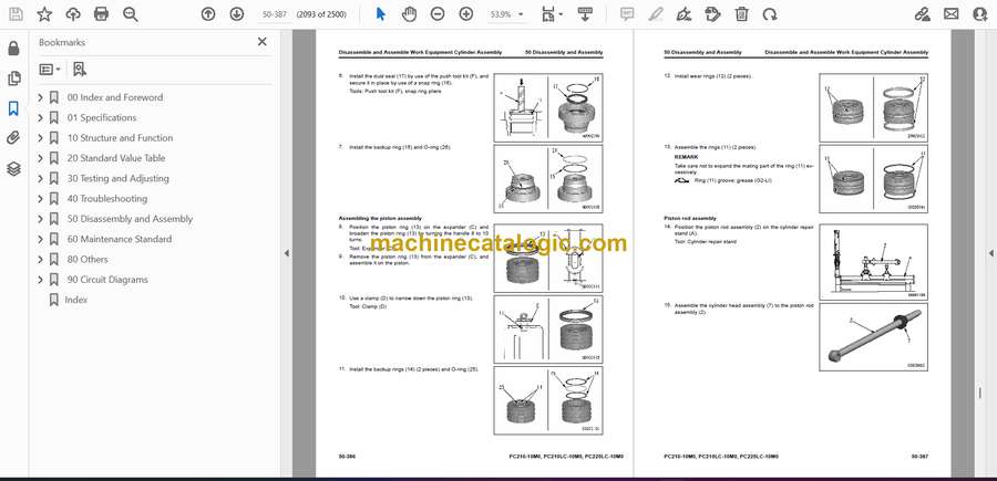
- Follow teardown and reassembly sequences for major components like the final drives, swing machinery, cylinders, and travel motors.
- Check and reset machine adjustments after repairs, including items that affect digging performance, tracking, and attachment response.
- Handle electrical and electronic faults by following wiring diagrams and troubleshooting flow that cover sensors, controllers, and harnesses.
Who this is for
This is aimed at field techs, shop mechanics, and fleet managers who schedule and oversee workshop‑level repairs. It’s not the right fit for operators who just need daily checks or basic maintenance; they’re better off with the Operation & Maintenance Manual.
FAQ
Q: Is this a searchable PDF I can download and print?
A: Yes, this type of shop manual is normally supplied as a downloadable PDF you can search on-screen and print selected pages for the shop.
Q: Does it go deep enough for full overhauls, or just basic servicing?
A: The Komatsu PC210-10M0, PC210LC-10M0, PC225LC-10M0 Crawler Excavator Shop Manual (SEN06701-CC) is intended for workshop repairs, including major disassembly and diagnostic procedures.
Q: How do I know if it matches my exact machine version or serial range?
A: You’ll want to confirm your machine plate against the SEN06701-CC reference with your dealer or supplier so the procedures and specs match your specific variant.
Bottom line: If you’re planning or performing real shop repairs on these models, this is the manual you want; if you just need operating tips and basic service intervals, keep looking for the O&M book instead.
📘 Show Index
Table of Contents:
- 00 Index and Foreword
- Index
- Abbreviation List
- Foreword, Safety, Basic Information
- How to Read the Shop Manual
- Safety Notice for Operation
- Precautions to Prevent Fire
- Procedures If Fire Occurs
- Precautions When You Dispose of Waste Materials
- Precautions When You Handle Hydraulic Equipment
- Precautions When You Disconnect and Connect Pipings
- Precautions When You Handle Electrical Equipment
- Precautions When You Handle Fuel System Equipment
- Precautions When You Handle Intake System Equipment
- Practical Use of KOMTRAX
- Disconnect and Connect Push-Pull Type Coupler
- How to Disconnect and Connect Type 1 Push-Pull Type Coupler
- How to Disconnect and Connect Type 2 Push-Pull Type Coupler
- How to Disconnect and Connect Type 3 Push-Pull Type Coupler
- Precautions for Disconnection and Connection of Connectors
- How to Disconnect and Connect Deutsch Connector
- How to Disconnect and Connect Slide Lock Type Connector
- How to Disconnect and Connect Connector with Lock to Pull
- How to Disconnect and Connect Connector with Lock to Push
- How to Disconnect and Connect Connector with Housing to Rotate
- How to Read the Codes for Electric Cable
- Explanation of Terms for Maintenance Standard
- Standard Tightening Torque Table
- Conversion Table
- 01 Specifications
- Table of Contents
- Specifications
- Specification Drawing
- Specification Drawing: PC210-10M0
- Specification Drawing: PC210LC-10M0
- Specification Drawing: PC225LC-10M0
- Working Range Drawings
- Working Range: PC210-10M0
- Working Range Drawings PC210LC-10M0
- Working Range Drawings PC225LC-10M0
- Specifications
- Specifications PC210-10M0
- Specifications PC210LC-10M0
- Specifications PC225LC-10M0
- Weight Table
- Weight Table: PC210-10M0
- Weight Table: PC210LC-10M0
- Weight Table: PC225LC-10M0
- Fuel, Coolant and Lubricant to Meet Ambient Temperature
- 10 Structure and Function
- Table of Contents
- Boot-up System
- Layout Drawing of Boot-up System
- System Operating Lamp System
- System Diagram of System Operating Lamp System
- Function of Operation Lamp System
- Operation of System Operating Lamp
- Battery Disconnect Switch
- Function of Battery Disconnect Switch
- Operation of Battery Disconnect Switch
- Engine System
- Layout Drawing of Engine System
- Engine Control System
- System Diagram of Engine Control
- Operation of Engine Control System
- Auto-Deceleration System
- System Diagram of Auto-Deceleration System
- Function of Auto-Deceleration System
- Operation of Auto-Deceleration System
- Engine Automatic Warm-up System
- System Diagram of Engine Automatic Warm-up System
- Function of Engine Automatic Warm-up System
- Operation of Engine Automatic Warm-up System
- Overheat Prevention System
- Overheat Prevention System Diagram
- Function of Overheat Prevention System
- Operation of Overheat Prevention System
- Turbocharger Protection System
- Function of Turbocharger Protection System
- Cooling System
- Layout Drawing of Cooling System
- Specifications of Cooling System
- Control System
- Layout Drawing of Control System
- Machine Monitor System
- System Diagram of Machine Monitor System
- Function of Machine Monitor System
- KOMTRAX System
- System Diagram of KOMTRAX System
- Function of KOMTRAX System
- Component Parts of Control System
- Machine Monitor
- KOMTRAX Terminal
- Pump Controller
- Resistor for PC-EPC Valve
- CAN Terminating Resistor
- Engine Controller
- Fuel Control Dial
- Hydraulic System
- Layout Drawing of Hydraulic System
- CLSS
- System Diagram of CLSS
- Function of CLSS
- Pressure Compensation Control
- Engine and Pump Combined Control System
- Engine and Pump Combined Control System Diagram
- Function of Engine and Pump Combined Control System
- Pump and Valve Control System
- Pump and Valve Control System Diagram
- Function of Pump and Valve Control System
- Component Parts of Hydraulic System
- Hydraulic Tank
- Main Pump
- Control Valve
- Work Equipment System
- Layout Drawing of Work Equipment System
- One-Touch Power Maximizing System
- System Diagram of One-Touch Power Maximizing System
- Function of One-Touch Power Maximizing System
- PPC Lock System
- System Diagram of PPC Lock
- Function of PPC Lock System
- Attachment Oil Flow Adjuster System
- Attachment Oil Flow Adjuster System Diagram
- Function of Attachment Oil Flow Adjuster System
- Component Parts of Work Equipment System
- Work Equipment and Swing PPC Valve
- 1st-Line Attachment PPC Valve (with EPC Valve)
- 2nd-Line Attachment PPC Valve
- Solenoid Valve
- Attachment Circuit Selector Valve (For High Pressure)
- Attachment Circuit Selector Valve (For Low Pressure)
- Pilot Circuit Accumulator
- Attachment Circuit Accumulator
- Swing System
- Layout Drawing of Swing System
- Swing Control System Diagram
- Function of Swing Control System
- Component Parts of Swing System
- Swing Motor
- Swing Machinery
- Swing Circle
- Travel System
- Layout Drawing of Travel System
- System Diagram of Travel Control System
- Function of Travel Control System
- Component Parts of Travel System
- Travel Motor
- Final Drive
- Travel PPC Valve
- Center Swivel Joint
- Function of Swing Circle
- Undercarriage and Frame
- Layout Drawing of Undercarriage
- Specifications of Undercarriage
- Work Equipment
- Structure of Work Equipment
- Work Equipment Clearance Adjustment Shim
- Function of Work Equipment Clearance Adjustment Shim
- Bucket Clearance Adjustment Shim
- Function of Bucket Clearance Adjustment Shim
- CAB Related Parts
- ROPS CAB
- Structure of ROPS CAB
- Function of ROPS CAB
- CAB Mount
- Structure of CAB Mount
- Function of CAB Mount
- CAB Tipping Stopper
- Structure of CAB Tipping Stopper
- Function of CAB Tipping Stopper
- 20 Standard Value Table
- Table of Contents
- Standard Value Table for Engine
- Standard Value Table for Engine: PC210-10M0
- Standard Value Table for Engine: PC210LC-10M0/PC225LC-10M0
- Standard Value Table for Machine: PC210-10M0
- Standard Value Table for Machine: PC210LC-10M0/PC225LC-10M0
- Machine Posture and Procedures to Measure Performance
- 30 Testing and Adjusting
- Table of Contents
- Precautions Before Work
- Related Information on Testing and Adjusting
- Tools for Testing and Adjusting
- Sketch of Tools for Testing and Adjusting
- Engine and Cooling System
- Examine Engine Speed
- How to Examine Engine High Idle Speed
- How to Examine Engine Low Idle Speed
- How to Examine Engine Speed at 2 Pump Relief
- Test Engine Speed at 2 Pumps Relief and One-touch Power Maximizing
- How to Examine Engine Speed with Auto-Deceleration
- Examine Boost Pressure
- How to Examine Boost Pressure on Machine Monitor
- How to Examine Boost Pressure by Testing Tool
- Examine Exhaust Gas Color
- How to Examine Exhaust Gas Color with the Handy Smoke Checker
- How to Examine Exhaust Gas Color with Smoke Meter
- Examine Mass Air Flow and Temperature Sensor
- How to Examine Mass Air Flow and Temperature Sensor
- Examine and Adjust Valve Clearance
- How to Examine Valve Clearance
- How to Adjust Valve Clearance
- Examine Compression Pressure
- How to Examine Compression Pressure
- Examine Blowby Pressure
- How to Examine Blowby Pressure on Machine Monitor (Machine with Blowby Pressure Sensor (OPT))
- How to Examine Blowby Pressure (Machine Without Blowby Pressure Sensor)
- Examine Engine Oil Pressure
- How to Examine Engine Oil Pressure
- Examine Fuel Pressure
- How to Examine Fuel Pressure
- Examine Fuel Discharge, Return and Leakage
- How to Examine Fuel Discharge, Return, and Leakage
- Bleed Air from Fuel System
- How to Bleed Air from Fuel System
- Examine Fuel Circuit for Leakage
- How to Examine Fuel System for Leakage
- Handle Cylinder Cut-out Mode Operation
- Handle No-Injection Cranking Operation
- Examine and Adjust Air Conditioner Compressor Belt Tension
- How to Examine Air Conditioner Compressor Belt
- How to Adjust Air Conditioner Compressor Belt
- Power Train
- Examine Swing Circle Bearing Clearance
- How to Examine Swing Circle Bearing Clearance
- Undercarriage and Frame
- Examine and Adjust Track Tension
- How to Examine Track Tension
- How to Adjust Track Tension
- Hydraulic System
- Release Remained Pressure in Hydraulic Circuit
- How to Release Remained Pressure from Hydraulic Tank
- How to Release Remained Pressure in Hydraulic Cylinder Circuit
- How to Release Remained Pressure for Machines Without Anti-drop Valve
- How to Release Remained Pressure for Machines with Boom Anti-drop Valve
- How to Release Remained Pressure from Swing Motor Circuit
- How to Release Remained Pressure from Travel Motor Circuit
- Examine and Adjust Oil Pressure in Work Equipment, Swing, and Travel Circuits
- How to Examine Oil Pressure in Work Equipment, Swing, and Travel Circuits
- How to Adjust Oil Pressure in Work Equipment, Swing, and Travel Circuits
- Examine Oil Pressure of Control Circuit
- How to Examine Oil Pressure in Control Circuit
- Examine and adjust oil pressure in pump PC control circuit
- How to Examine PC Valve Outlet Pressure (Servo Piston Inlet Pressure)
- How to Examine PC-EPC Valve Outlet Pressure
- How to Adjust Oil Pressure in Pump PC Control Circuit
- Examine and Adjust Oil Pressure in Pump LS Control Circuit
- How to Examine LS Differential Pressure with Machine Monitor
- How to Examine LS Differential Pressure by Testing Tool
- How to Examine LS Valve Outlet Pressure (Servo Piston Inlet Pressure)
- How to Examine LS-EPC Valve Outlet Pressure
- How to Adjust LS Valve
- Examine Outlet Pressure of Solenoid Valve
- How to Examine Outlet Pressure of Solenoid Valve
- Operating Condition of Solenoid Valve
- Examine PPC Valve Outlet Pressure
- How to Examine PPC Valve Outlet Pressure on Machine Monitor
- How to Examine PPC Valve Outlet Pressure by Testing Tool
- Adjust Play of Work Equipment and Swing PPC Valve
- How to Adjust play of work equipment and swing PPC valve
- Examine Pump Swash Plate Sensor
- How to Examine pump swash plate sensor
- Examine parts which cause hydraulic drift of work equipment
- How to Examine Parts Which Cause Hydraulic Drift of Boom Cylinder and Bucket Cylinder
- How to Examine the Parts Which Cause Hydraulic Drift of Arm Cylinder
- How to Examine Parts Which Cause Hydraulic Drift of Boom Hydraulic Drift Prevention Valve
- How to Examine Parts Which Cause Hydraulic Drift of PPC Valve
- Examine Oil Leakage
- How to Examine Oil Leakage from Boom Cylinder
- How to Examine Oil Leakage from Arm Cylinder
- How to Examine Oil Leakage from Bucket Cylinder
- How to Examine Oil Leakage from Swing Motor
- How to Examine Oil Leakage from Travel Motor
- Bleed Air from Hydraulic System
- How to Bleed Air from Main Pump
- How to Bleed Air from Cylinder
- How to Bleed Air from Swing Motor
- How to Bleed Air from Travel Motor
- CAB Related Parts
- Examine CAB Tipping Stopper
- How to Examine Cab Tipping Stopper
- How to Adjust Mirrors
- How to Adjust Machine Left Front Mirror (A)
- Adjust regular position of machine left front mirror (A)
- How to Adjust Machine Right Front Mirror (B)
- How to Adjust Regular Position of Machine Right Front Mirror (B)
- How to Adjust Machine Right Side Mirror (C)
- Electrical System
- Set and Operate Machine Monitor
- Operator Mode
- Function to Show Technician Identification Status Screen
- Function to Show Operator Identification Input Screen
- Examine Function by LCD (Liquid Crystal Display)
- Examine Function of Service Meter
- How to Set Usage Limitation and Change Maintenance Password
- Service Mode
- How to Operate Service Mode
- How to See Pre-defined Monitoring Information
- How to Examine Monitoring Information
- Abnormality Record Menu
- How to See Maintenance Record
- Maintenance Mode Setting
- How to Set Phone Number Entry
- Default Setting Menu
- Testing Menu
- Adjustment Menu
- No-Injection Cranking Operation
- KOMTRAX Settings Menu
- How to Show Service Message
- How to Start Up KOMTRAX Terminal
- Adjust Rearview Camera Angle
- How to Adjust Rearview Camera Angle
- Handle Voltage Circuit of Engine Controller
- Examine Diodes
- How to Examine Diodes by Digital Tester
- How to Examine Diodes by Analog Tester
- Pm Clinic
- Pm Clinic Service
- Pm Clinic Check Sheet: PC210-10M0
- Pm Clinic Check Sheet: PC210LC-10M0
- 40 Troubleshooting
- Table of Contents
- Precautions Before Work
- Related Information to Troubleshooting
- Precautions for Troubleshooting
- Sequence of Events in Troubleshooting
- Checks Before Troubleshooting
- Inspection Procedure Before Troubleshooting
- Walk-Around Check
- Examine Engine Related Parts
- Examine Work Equipment and Undercarriage
- Examine Electric Equipment
- How to Connect Adapter for Troubleshooting Controller
- How to Connect Adapter for Troubleshooting Machine Monitor
- How to Connect Adapter to Troubleshoot Pump Controller
- How to Connect Adapter to Troubleshoot KOMTRAX Terminal
- How to Connect Adapter for Troubleshooting Engine Controller
- How to Connect Adapter to Troubleshoot Engine Intermediate Connector
- Disconnect and Connect Connector with Lock to Push
- How to Disconnect and Connect Deutsch Connector
- How to Disconnect and Connect BOSCH Connector
- How to Disconnect and Connect AMP Connector
- How to Disconnect and Connect SUMITOMO Connector
- How to Disconnect and Connect Connector with Lock to Pull
- How to Disconnect and Connect DELPHI Connector and PACKARD Connector
- How to Disconnect and Connect Slide Type Connector
- How to Disconnect and Connect Framatome Connector
- How to Disconnect and Connect TYCO Connector
- How to Disconnect and Connect Connector with Housing to Rotate
- Procedure for Troubleshooting
- Information Shown in Troubleshooting
- How to Diagnose Open Circuit of Hydraulic Pressure Sensor System Wiring Harness
- Connector and Wiring Harness Identification Table
- Connector Layout
- Connector Contact Connection Table
- T-Branch Box and T-Branch Adapter Table
- Fuse Location and Connection Table
- Drawing of Short Circuit Electrical Connector for Troubleshooting
- Failure Code Table
- Troubleshooting by Failure Code (Display of Code)
- Failure Code [602KNX]
- Failure Code [6AZ0ZG]
- Failure Code [879AKA]
- Failure Code [879AKB]
- Failure Code [879BKA]
- Failure Code [879BKB]
- Failure Code [879CKA]
- Failure Code [879CKB]
- Failure Code [879DKZ]
- Failure Code [879EMC]
- Failure Code [879FMC]
- Failure Code [879GKX]
- Failure Code [989L00]
- Failure Code [989M00]
- Failure Code [989N00]
- Failure Code [AA10NX]
- Failure Code [AB00KE]
- Failure Code [B@BAZG]
- Failure Code [B@BAZK]
- Failure Code [B@BCZK]
- Failure Code [B@BCNS]
- Failure Code [B@BCQA]
- Failure Code [B@HANS]
- Failure Code [CA111]
- Failure Code [CA115]
- Engine NE (Crankshaft) Speed Sensor
- Failure Code [CA122]
- Failure Code [CA123]
- Failure Code [CA131]
- Failure Code [CA132]
- Failure Code [CA144]
- Failure Code [CA145]
- Failure Code [CA153]
- Failure Code [CA154]
- Failure Code [CA155]
- Failure Code [CA187]
- Failure Code [CA221]
- Failure Code [CA222]
- Failure Code [CA227]
- Failure Code [CA234]
- Failure Code [CA238]
- Failure Code [CA271]
- Failure Code [CA272]
- Failure Code [CA322]
- Failure Code [CA323]
- Failure Code [CA324]
- Failure Code [CA325]
- Failure Code [CA331]
- Failure Code [CA332]
- Failure Code [CA342]
- Failure Code [CA351]
- Failure Code [CA352]
- Failure Code [CA386]
- Failure Code [CA435]
- Failure Code [CA441]
- Failure Code [CA442]
- Failure Code [CA449]
- Failure Code [CA451]
- Failure Code [CA452]
- Failure Code [CA488]
- Failure Code [CA553]
- Failure Code [CA559]
- Examine Low Pressure Fuel Circuit Devices
- Failure Code [CA689]
- Failure Code [CA731]
- Installation Points of Crankshaft and Camshaft Speed Sensors
- Failure Code [CA757]
- Failure Code [CA778]
- Engine NE (Crankshaft) Speed Sensor
- Failure Code [CA2185]
- Failure Code [CA2186]
- Failure Code [CA2249]
- Examine Low Pressure Fuel Circuit Devices
- Failure Code [CA2311]
- Failure Code [CA2555]
- Failure Code [CA2556]
- Failure Code [D110KB]
- Failure Code [D19JKZ]
- Failure Code [D1N0KA]
- Failure Code [D1N0KB]
- Failure Code [D1N0KY]
- Failure Code [D811MC]
- Failure Code [D862KA]
- Failure Code [D8AQKR]
- Failure Code [D8ALKA]
- Failure Code [D8ALKB]
- Failure Code [DA20MC]
- Failure Code [DA22KK]
- Failure Code [DA25KP]
- Failure Code [DA26KP]
- Failure Code [DA29KQ]
- Failure Code [DA2LKA]
- Failure Code [DA2LKB]
- Failure Code [DA2QKR]
- Failure Code [DA2RKR]
- Failure Code [DAF0MB]
- Failure Code [DAF0MC]
- Failure Code [DAF8KB]
- Failure Code [DAF9KQ]
- Failure Code [DAFGMC]
- Failure Code [DAFLKA]
- Failure Code [DAFLKB]
- Failure Code [DAFQKR]
- Failure Code [DAZ9KQ]
- Failure Code [DAZQKR]
- Failure Code [DB2QKR]
- Failure Code [DDPAKA]
- Failure Code [DGH2KA]
- Failure Code [DGH2KB]
- Failure Code [DHA4KA]
- Failure Code [DHE5MA]
- Failure Code [DHPAMA]
- Failure Code [DHPBMA]
- Failure Code [DHS3MA]
- Failure Code [DHS4MA]
- Failure Code [DHS8MA]
- Failure Code [DHS9MA]
- Failure Code [DHSAMA]
- Failure Code [DHSBMA]
- Failure Code [DHSCMA]
- Failure Code [DHSDMA]
- Failure Code [DHSFMA]
- Failure Code [DHSGMA]
- Failure Code [DHSHMA]
- Failure Code [DHSJMA]
- Failure Code [DJG1KX]
- Failure Code [DKR0MA]
- Failure Code [DKR1MA]
- Failure Code [DKR2MA]
- Failure Code [DKR2NX]
- Failure Code [DLM5KA]
- Failure Code [DLM5MB]
- Failure Code [DR21KX]
- Failure Code [DR31KX]
- Failure Code [DV20KB]
- Failure Code [DW43KA]
- Failure Code [DW43KB]
- Failure Code [DW43KY]
- Failure Code [DW45KA]
- Failure Code [DW45KB]
- Failure Code [DW45KY]
- Failure Code [DW91KA]
- Failure Code [DW91KB]
- Failure Code [DW91KY]
- Failure Code [DW97KA]
- Failure Code [DW97KB]
- Failure Code [DW97KY]
- Failure Code [DWA2KA]
- Failure Code [DWA2KB]
- Failure Code [DWA2KY]
- Failure Code [DWK0KA]
- Failure Code [DWK0KB]
- Failure Code [DWK0KY]
- Failure Code [DWK2KA]
- Failure Code [DWK2KB]
- Failure Code [DWK2KY]
- Failure Code [DWK8KA]
- Failure Code [DWK8KB]
- Failure Code [DWK8KY]
- Failure Code [DWN5KA]
- Failure Code [DWN5KB]
- Failure Code [DWN5KY]
- Failure Code [DXA8KA]
- Failure Code [DXA8KB]
- Failure Code [DXA9KA]
- Failure Code [DXA9KB]
- Failure Code [DXE0KA]
- Failure Code [DXE0KB]
- Failure Code [DXE4KA]
- Failure Code [DXE4KB]
- Failure Code [DXE4KY]
- Failure Code [DXE5KA]
- Failure Code [DXE5KB]
- Failure Code [DXE6KA]
- Failure Code [DXE6KB]
- Failure Code [DY20KA]
- Failure Code [DY20MA]
- Failure Code [DY2CKB]
- Failure Code [DY2DKB]
- Failure Code [DY2EKB]
- Failure Code [F@BBZL]
- Troubleshooting of Electrical System (E-Mode)
- Engine Does Not Start (Engine Does Not Crank)
- Manual Preheating System Does Not Operate
- Automatic Preheating System Does Not Operate
- While Preheating is in Operation, Preheating Monitor Does Not Come On
- When Starting Switch is Turned to ON Position, Machine Monitor Shows Nothing
- While Starting Switch is Turned to ON Position (with Engine Stopped), Engine Oil Level Monitor Comes On in Yellow
- While Starting Switch is Turned to ON Position (with Engine Stopped), Radiator Coolant Level Monitor Comes On in Yellow
- Engine Coolant Temperature Monitor Comes On in White While Engine is in Operation
- Hydraulic Oil Temperature Monitor Comes On in White While Engine is in Operation
- Air Cleaner Clogging Monitor Comes On in Yellow While Engine is in Operation
- Charge Level Monitor Comes On in Red While Engine is in Operation
- Fuel Level Monitor Comes On in Red While Engine is in Operation
- Water Separator Monitor Comes On in Red While Engine is in Operation
- Engine Coolant Temperature Monitor Comes On in Red While Engine is in Operation
- Engine Oil Pressure Monitor Comes On in Red While Engine is in Operation
- Hydraulic Oil Temperature Monitor Comes On in Red While Engine is in Operation
- Fuel Gauge Does Not Move from Minimum or Maximum
- Display of Fuel Gauge is Different from Actual Fuel Level
- Coolant Temperature Gauge Display Does Not Move from Minimum or Maximum
- Display of Coolant Temperature Gauge is Different from Actual Coolant Temperature
- Hydraulic Oil Temperature Gauge Does Not Move from Minimum or Maximum
- Display of Hydraulic Oil Temperature Gauge is Different from Actual Oil Temperature
- Machine Monitor Shows Incorrect Model
- Some Areas of Machine Monitor Screen are Not Shown
- Function Switch Does Not Operate
- Automatic Warm-up System Does Not Operate (in Cold Weather)
- Auto-Deceleration Monitor Does Not Come On or Go Out While Auto-Deceleration Switch is Operated
- Auto-Decelerator is Not Operated or Canceled with Lever
- Work Mode Selector Screen is Not Shown While Work Mode Switch is Operated
- When Working Mode is Changed, Setting of Engine and Hydraulic Pump is Not Changed
- Travel Speed Monitor Does Not Change While Travel Speed Switch is Operated
- Travel Speed Does Not Change Even When You Change Travel Speed
- Alarm Buzzer Does Not Stop
- Service Meter is Not Shown While Starting Switch is in OFF Position
- Service Mode Cannot be Selected
- All Work Equipment, Swing, Travel Do Not Operate
- All Work Equipment, Swing, Travel Cannot be Locked
- Machine Does Not Swing While Swing Parking Brake Release Switch is Set to Release Position
- While Swing Parking Brake Release Switch is Turned on, Swing Brake is Not Operated
- One-Touch Power Maximizing Function Does Not Operate Correctly or Monitor is Not Shown
- One-Touch Power Maximizing Function is Not Cancelled
- Travel Alarm Does Not Operate During Travel
- Travel Alarm Does Not Stop When Machine Stops
- Horn Does Not Sound
- Horn Does Not Stop
- Wiper Monitor Does Not Come On or Go Out While Wiper Switch is Operated
- Windshield Wiper Does Not Operate When Wiper Switch is Operated
- When Window Washer Switch is Operated, Window Washer Does Not Operate
- Boom Raise is Not Shown Normally with Monitoring Function
- Boom Lower is Not Shown Normally with Monitoring Function
- Arm OUT is Not Shown Correctly with Monitoring Function
- Arm IN is Not Shown Normally with Monitoring Function
- Bucket DUMP is Not Shown Correctly with Monitoring Function
- Bucket CURL is Not Shown Correctly with Monitoring Function
- Swing is Not Shown Normally with Monitoring Function
- Travel is Not Shown Normally with Monitoring Function
- Service is Not Shown Correctly with Monitoring Function
- Attachment Hydraulic Circuit Cannot be Changed
- KOMTRAX System Does Not Operate Correctly
- Quick Coupler Does Not Work
- Troubleshooting for Hydraulic and Mechanical Systems (H Mode)
- Information Shown in Troubleshooting Table (H-Mode)
- All Work Equipment, Swing and Travel Do Not Work
- All Work Equipment, Swing, and Travel Lack Speed or Power
- Fine Control Performance or Response is Unsatisfactory
- Unusual Noise is Heard from Around Hydraulic Pump
- Engine Speed Drops Largely or Engine Stops
- Boom Speed or Power is Low
- Arm Speed or Power is Low
- Bucket Speed or Power is Low
- Work Equipment Does Not Move in Single Operation
- Hydraulic Drift of Boom is Large
- Hydraulic Drift of Arm is Large
- Hydraulic Drift of Bucket is Large
- When Single Work Equipment is Released Hydraulically, Other Work Equipment Moves
- Time Lag of Work Equipment is Large
- One-Touch Power Maximizing Function Does Not Operate
- Attachment Circuit Cannot be Changed
- Oil Flow in Attachment Circuit Cannot be Changed
- In Mixed Operation of Work Equipment, Work Equipment with Heavier Load Moves Slower
- In Mixed Operation of Swing and Travel, Travel Speed Falls Largely
- In Mixed Operation of Swing and Boom RAISE, Boom RAISE Speed is Low
- Machine Does Not Travel Straight
- Machine is Not Steered Well or Steering Power is Low
- Travel Speed is Low
- One of Tracks Does Not Run
- Travel Speed Does Not Change, or Travel Speed is Too Slow or Fast
- Upper Structure Does Not Swing in Two Directions of Right and Left
- Machine Swings Only in One Direction
- Swing Acceleration or Swing Speed is Low in Two Directions of Right and Left
- Swing Acceleration or Swing Speed is Low in Only One Direction
- Upper Structure Overruns Too Much When It Stops Swing Operation (Right and Left)
- Upper Structure Overruns Too Much When It Stops Swing Operation (Only One Direction)
- Shock is Large When Upper Structure Stops Swing Operation
- Large Unusual Noise is Heard When Upper Structure Stops
- Swing Drift on a Slope is Large (While Swing Parking Brake is Applied)
- Swing Drift on a Slope is Large (While Swing Parking Brake is Released)
- Fan Speed is Abnormal (Too High or Low, or Does Not Move)
- Unusual Noise is Heard from Around Fan
- 50 Disassembly and Assembly
- Table of Contents
- Precautions Before Work
- Related Information on Disassembly and Assembly
- How to Read This Manual
- Coating Materials List
- Special Tool List
- Sketches of Special Tools
- Prepare
- Drain and Add Coolant
- How to Drain Coolant
- How to Add Coolant
- Drain and Add Hydraulic Oil
- How to Drain Hydraulic Oil
- How to Add Hydraulic Oil
- Drain and Add Fuel
- How to Drain Fuel
- How to Add Fuel
- Collect and Refill Refrigerant
- How to Collect Refrigerant
- How to Refill Refrigerant
- Engine and Cooling System
- Remove and Install Supply Pump Assembly
- How to Remove Supply Pump Assembly
- How to Install Supply Pump Assembly
- Remove and Install Injector Assembly
- How to Remove Injector Assembly
- How to Install Injector Assembly
- Remove and Install Cylinder Head Assembly
- How to Remove Cylinder Head Assembly
- How to Install Cylinder Head Assembly
- Remove and Install Starter Assembly
- How to Remove Starting Motor Assembly
- How to Install Starting Motor Assembly
- Remove and Install Alternator Belt
- How to Remove Alternator Belt
- How to Install Alternator Belt
- Remove and Install Radiator Assembly
- How to Remove Radiator Assembly
- How to Install Radiator Assembly
- Remove and Install Hydraulic Oil Cooler Assembly
- How to Remove Hydraulic Oil Cooler Assembly
- How to Install Hydraulic Oil Cooler Assembly
- Remove and Install Aftercooler Assembly
- How to Remove Aftercooler Assembly
- How to Install Aftercooler Assembly
- Remove and Install Fan Clutch Assembly
- How to Remove Fan Clutch Assembly
- How to Install Fan Clutch Assembly
- Remove and Install Fan
- How to Remove Fan
- How to Install Fan
- Remove and Install Engine and Main Pump Assembly
- How to Remove Engine and Main Pump Assembly
- How to Install Engine and Main Pump Assembly
- Remove and Install Engine Front Oil Seal
- How to Remove Engine Front Oil Seal
- How to Install Engine Front Oil Seal
- Remove and Install Engine Rear Oil Seal
- How to Remove Engine Rear Oil Seal
- How to Install Engine Rear Oil Seal
- Remove and Install Fuel Cooler Assembly
- How to Remove Fuel Cooler Assembly
- How to Install Fuel Cooler Assembly
- Remove and Install Engine Hood Assembly
- How to Remove Engine Hood Assembly
- How to Install Engine Hood Assembly
- Remove and Install Fuel Tank Assembly
- How to Remove Fuel Tank Assembly
- How to Install Fuel Tank Assembly
- Remove and Install Air Cleaner Assembly
- How to Remove Air Cleaner Assembly
- How to Install Air Cleaner Assembly
- Remove and Install Air Conditioner Compressor Assembly
- How to Remove Air Conditioner Compressor Assembly
- How to Install Air Conditioner Compressor Assembly
- Remove and Install Air Conditioner Condenser Assembly
- How to Remove Air Conditioner Condenser Assembly
- How to Install Air Conditioner Condenser Assembly
- Power Train
- Remove and Install Travel Motor and Final Drive Assembly
- How to Remove Travel Motor and Final Drive Assembly
- How to Install Travel Motor and Final Drive Assembly
- Disassemble and Assemble Final Drive Assembly
- How to Disassemble Final Drive Assembly
- How to Assemble Final Drive Assembly
- Remove and Install Swing Motor and Swing Machinery Assembly
- How to Remove Swing Motor and Swing Machinery Assembly
- How to Install Swing Motor and Swing Machinery Assembly
- Disassemble and Assemble Swing Machinery Assembly
- How to Disassemble Swing Machinery Assembly
- How to Assemble Swing Machinery Assembly
- Remove and Install Swing Circle Assembly
- How to Remove Swing Circle Assembly
- How to Install Swing Circle Assembly
- Undercarriage and Frame
- Separate and Connect Track Assembly
- How to Separate Track Assembly
- How to Install Track Assembly
- Remove and Install Sprocket
- How to Remove Sprocket
- How to Install Sprocket
- Remove and Install Idler and Idler Cushion Assembly
- How to Remove Idler and Idler Cushion Assembly
- How to Install Idler and Idler Cushion Assembly
- Disassemble and Assemble Idler Assembly
- How to Disassemble Idler Assembly
- How to Assemble Idler Assembly
- Disassemble and Assemble Idler Cushion Assembly
- How to Disassemble Idler Cushion Assembly
- How to Assemble Idler Cushion Assembly
- Disassemble and Assemble Track Roller Assembly
- How to Disassemble Track Roller Assembly
- How to Assemble Track Roller Assembly
- Disassemble and Assemble Carrier Roller Assembly
- How to Disassemble Carrier Roller Assembly
- How to Assemble Carrier Roller Assembly
- Remove and Install Revolving Frame Assembly
- How to Remove Revolving Frame Assembly
- How to Install Revolving Frame Assembly
- Remove and Install Counterweight Assembly
- How to Remove Counterweight Assembly
- How to Install Counterweight Assembly
- Hydraulic System
- Remove and Install Center Swivel Joint Assembly
- How to Remove Center Swivel Joint Assembly
- How to Install Center Swivel Joint Assembly
- Disassemble and Assemble Center Swivel Joint Assembly
- How to Disassemble Center Swivel Joint Assembly
- How to Assemble Center Swivel Joint Assembly
- Remove and Install Hydraulic Tank Assembly
- How to Remove Hydraulic Tank Assembly
- How to Install Hydraulic Tank Assembly
- Remove and Install Main Pump Assembly
- How to Remove Main Pump Assembly
- How to Install Main Pump Assembly
- Remove and Install Control Valve Assembly
- How to Remove Control Valve Assembly
- How to Install Control Valve Assembly
- Disassemble and Assemble Control Valve Assembly
- How to Replace Pressure Compensation Valve Seal Ring
- Disassemble and Assemble Work Equipment PPC Valve Assembly
- How to Disassemble Work Equipment PPC Valve Assembly
- How to Assemble Work Equipment PPC Valve Assembly
- Disassemble and Assemble Travel PPC Valve Assembly
- How to Disassemble Travel PPC Valve Assembly
- How to Assemble Travel PPC Valve Assembly
- Work Equipment
- Remove and Install Work Equipment Assembly
- How to Remove Work Equipment Assembly
- How to Install Work Equipment Assembly
- Disassemble and Assemble Work Equipment Cylinder Assembly
- How to Disassemble Work Equipment Cylinder Assembly
- How to Assemble Work Equipment Cylinder Assembly
- CAB Related Parts
- Remove and Install Operator Cab Assembly
- How to Remove Operator Cab Assembly
- How to Install Operator Cab Assembly
- Remove and Install Operator Cab Glass (Adhered Glass)
- How to Remove Operator Cab Glass (Adhered Glass)
- How to Install Operator Cab Glass (Adhered Glass)
- Remove and Install Front Window Assembly
- How to Remove Front Window Assembly
- How to Install Front Window Assembly
- Remove and Install Floor Frame Assembly
- How to Remove Floor Frame Assembly
- How to Install Floor Frame Assembly
- Remove and Install Air Conditioner Unit Assembly
- How to Remove Air Conditioner Unit Assembly
- How to Install Air Conditioner Unit Assembly
- Remove and Install Operator Seat
- How to Remove Operator Seat
- How to Install Operator Seat
- How to Remove and Install Seat Belt
- How to Remove Seat Belt
- How to Install Seatbelt
- Remove and Install Work Equipment Control Lever Assembly
- How to Remove Work Equipment Control Lever Assembly
- How to Install Work Equipment Control Lever Assembly
- Remove and Install Front Wiper Assembly
- How to Remove Front Wiper Assembly
- How to Install Front Wiper Assembly
- Electrical System
- Remove and Install Engine Controller Assembly
- How to Remove Engine Controller Assembly
- How to Install Engine Controller Assembly
- Remove and Install Pump Controller Assembly
- How to Remove Pump Controller Assembly
- How to Install Pump Controller Assembly
- Remove and Install Machine Monitor Assembly
- How to Remove Machine Monitor Assembly
- How to Install Machine Monitor Assembly
- Remove and Install Pump Swash Plate Sensor
- How to Remove Pump Swash Plate Sensor
- How to Install Pump Swash Plate Sensor
- Remove and Install KOMTRAX Terminal Assembly
- How to Remove KOMTRAX Terminal Assembly
- How to Install KOMTRAX Terminal Assembly
- 60 Maintenance Standard
- Table of Contents
- Explanation of Terms for Maintenance Standard
- Engine and Cooling System
- Maintenance Standard for Engine Mount
- Maintenance Standard for Cooling System
- Power Train
- Maintenance Standard for Swing Circle
- Maintenance Standard for Swing Machinery
- Maintenance Standard for Final Drive
- Maintenance Standard for Sprocket
- Sprocket Tooth Profile Full-Scale Drawing
- Undercarriage and Frame
- Maintenance Standard for Track Frame and Idler Cushion
- Maintenance Standard for Idler
- Maintenance Standard for Track Roller
- Maintenance Standard for Carrier Roller
- Maintenance Standard for Track Shoes
- Maintenance Standard for Triple Shoes
- Maintenance Standard for Swamp Shoes
- Maintenance Standard for Road Liner
- Hydraulic System
- Maintenance Standard for Hydraulic Tank
- Maintenance Standard for Main Pump
- Maintenance Standard for LS-EPC Valve
- Maintenance Standard for PC-EPC Valve
- Maintenance Standard for Swing Motor
- Maintenance Standard for Travel Motor
- Maintenance Standard for Control Valve
- Maintenance Standard for PPC Valve (Work Equipment and Swing Operation)
- Maintenance Standard for Travel PPC Valve
- Maintenance Standard for 1st-Line Attachment PPC Valve (with EPC Valve)
- Maintenance Standard for Attachment Oil Flow Adjuster EPC Valve
- Maintenance Standard for 2nd-Line Attachment PPC Valve
- Maintenance Standard for Solenoid Valve
- Maintenance Standard for Attachment Circuit Selector Valve (For High Pressure)
- Maintenance Standard for Attachment Circuit Selector Valve (For Low Pressure)
- Maintenance Standard for Center Swivel Joint
- Work Equipment
- Maintenance Standard for Work Equipment Linkage
- Dimensions of Arm
- Dimensions of Bucket
- Maintenance Standard for Boom Cylinder
- Maintenance Standard for Arm Cylinder
- Maintenance Standard for Bucket Cylinder
- 80 Others
- Table of Contents
- Precautions Before Work
- Air Conditioner System
- Precautions for Refrigerant
- Layout Drawing of Air Conditioner System
- Specifications of Air Conditioner
- Structure of Refrigeration Cycle
- Function of Refrigeration Cycle
- System Diagram of Air Conditioner
- Component Parts of Air Conditioner System
- Air Conditioner Unit
- Structure of Air Conditioner Unit
- Function of Air Conditioner Unit
- Component Parts of Air Conditioner Unit
- Air Conditioner Controller
- Structure of Air Conditioner Controller
- Function of Air Conditioner Controller
- Input and Output Signals of Air Conditioner Controller
- Compressor
- Structure of Compressor
- Specifications of Compressor
- Function of Compressor
- Operation of Compressor
- Condenser
- Structure of Condenser
- Specifications of Condenser
- Function of Condenser
- Air Conditioner Related Sensors
- Structure of Sunlight Sensor
- Function of Sunlight Sensor
- Structure of Outside Temperature Sensor
- Function of Outside Air Temperature Sensor
- Circuit Diagram and Configuration of Connector Pins of Air Conditioner
- Locations of Air Conditioner Parts and Layout of Connectors
- Examine Air Leakage (Duct Connection)
- How to Examine Air Leakage (Duct Connection)
- Examine Air Conditioner with Self-Diagnosis Function
- Examine Vent (Mode) Changeover
- How to Examine Vent (Mode) Changeover
- Examine Fresh/Recirc Air Changeover
- How to Examine Fresh/Recirc Air Changeover
- Examine Sunlight Sensor
- How to Examine Sunlight Sensor
- Examine Dual Pressure Switch
- How to Examine Dual Pressure Switch
- Examine Relay
- Simple Check of Refrigerant Level Through Sight Glass
- Procedure for Troubleshooting of Air Conditioner
- Information Shown in Troubleshooting Table
- Failure Code [879AKA]
- Failure Code [879AKB]
- Failure Code [879BKA]
- Failure Code [879BKB]
- Failure Code [879CKA]
- Failure Code [879CKB]
- Failure Code [879DKZ]
- Failure Code [879EMC]
- Failure Code [879FMC]
- Failure Code [879GKX]
- Air Conditioner Does Not Operate
- Defective Cooling
- Heater Does Not Operate
- Cool Air Does Not Come Out
- No Air Comes Out or Air Flow is Abnormal
- Fresh/Recirc Air Changeover Does Not Work
- Connect Service Tool
- How to Connect Service Tool
- Precautions for Disconnection and Connection of Air Conditioner Piping
- Handle Compressor Oil
- How to Replace Desiccant
- 90 Circuit Diagrams
- Table of Contents
- How to Read the Codes for Electric Cable
- Hydraulic Circuit Diagram
- Symbols Used in Hydraulic Circuit Diagram
- Hydraulic Circuit Diagram
- Electrical Circuit Diagram
- Symbols Used in Electric Circuit Diagram
- Electrical Circuit Diagram (Applicable Machine: C00001-C03057 ) (1/7)
- Electrical Circuit Diagram (Applicable Machine: C00001-C03057 ) (2/7)
- Electrical Circuit Diagram (Applicable Machine: C00001-C03057 ) (3/7)
- Electrical Circuit Diagram (Applicable Machine: C00001-C03057) (4/7)
- Electrical Circuit Diagram (Applicable Machine: C00001-C03057) (5/7)
- Electrical Circuit Diagram (Applicable Machine: C00001-C03057) (6/7)
- Electrical Circuit Diagram (Applicable Machine: C00001-C03057) (7/7)
- Electrical Circuit Diagram (Applicable Machine: C03058/C90001 and Up) (1/7)
- Electrical Circuit Diagram (Applicable Machine: C03058/C90001 and Up) (2/7)
- Electrical Circuit Diagram (Applicable Machine: C03058/C90001 and Up) (3/7)
- Electrical Circuit Diagram (Applicable Machine: C03058/C90001 and Up) (4/7)
- Electrical Circuit Diagram (Applicable Machine: C03058/C90001 and Up) (5/7)
- Electrical Circuit Diagram (Applicable Machine: C03058/C90001 and Up) (6/7)
- Electrical Circuit Diagram (Applicable Machine: C03058/C90001 and Up) (7/7)
- Connector and Wiring Harness Chart
- Wiring Harness Diagram (1/11)
- Wiring Harness Diagram (2/11)
- Wiring Harness Diagram (3/11)
- Wiring Harness Diagram (4/11)
- Wiring Harness Diagram (5/11)
- Wiring Harness Diagram (6/11)
- Wiring Harness Diagram (7/11)
- Wiring Harness Diagram (8/11)
- Wiring Harness Diagram (9/11)
- Wiring Harness Diagram (10/11)
- Wiring Harness Diagram (11/11)
- Index
Komatsu


