The Komatsu GD755-5R Motor Grader is a production grader used for road building, maintenance, and heavy cutting and finishing work. People who reach for the Komatsu GD755-5R Motor Grader Shop Manual (SEN05668-10) are usually shop mechanics, field techs, or serious owner-operators. They’re trying to diagnose faults, tear down components correctly, and put the machine back together so it holds up in real-world grading conditions.
What this manual helps you do
- Trace hydraulic and electrical faults using circuit information and step‑by‑step diagnostic routines that these manuals typically include.
- Check engine, transmission, and final drive issues with guided test procedures and symptom-based troubleshooting charts.
- Follow correct disassembly and assembly sequences for major components so you don’t miss hidden fasteners, seals, or shims.
- Diagnose steering, braking, and blade control problems with the kind of flow and pressure checks you’d expect in a shop manual.
- Handle adjustments—linkages, blade controls, and machine set‑up—the way most dealers would, instead of guessing in the bay.
Who this is for
This manual is aimed at technicians doing workshop‑level repairs, whether you’re in a dealership, contractor shop, or training to be there. Operators wanting only daily checks and basic maintenance are usually better off with the Operation & Maintenance Manual, not this shop manual.
FAQ
Q: Is this a PDF I can search and print?
A: Yes, it’s a digital PDF you can search by keyword and print pages or sections for use at the bench.
Q: Is it deep enough for full rebuilds, or just basic service?
A: The Shop Manual for Komatsu GD755-5R Motor Grader walks through diagnostic procedures, disassembly sequences, and reference data used during workshop-level repairs.
Q: How do I know it matches my exact GD755-5R machine?
A: This is the Komatsu shop manual under reference SEN05668-10; you’ll want to match that reference and model designation against your machine plate or dealer info.
Bottom line: if you’re actually wrenching on a GD755-5R and need repair and diagnostic guidance, this is what you’re looking for; if you just run the grader and do light service, keep looking for the O&M manual instead.
📘 Show Index
Table of Contents:
- 00 Index and Foreword
- 100 Index
- Composition of shop manual
- Table of contents
- 200 Foreword and general information
- Safety notice
- How to read the shop manual
- Explanation of terms for maintenance standard
- Handling of hydraulic equipment
- Method of disconnecting and connecting push-pull type coupler
- Handling of electrical equipment
- How to read electric wire code
- Precautions when performing operation
- Standard tightening torque table
- List of abbreviation
- Conversion table
- 01 Specification
- 100 Specification and technical data
- Specification drawing
- Specifications
- Weight table
- Table of fuel, coolant and lubricants
- 10 Structure, function and maintenance standard
- 100 Engine and cooling system
- Engine mount and transmission mount
- Cooling system
- Cooling fan pump
- Cooling fan motor
- Cooling fan relief valve
- 200 Power train
- Power train system drawing
- Power train piping drawing
- Transmission control
- Torque converter
- Transmission
- Transmission control valve
- ECMV
- Main relief and torque converter relief valve
- Front axle
- Final drive
- Differential
- Differential lock solenoid valve
- Tandem drive
- 300 Steering system
- Steering piping diagram
- Priority valve
- Accumulator charge valve
- Steering valve
- 400 Brake system
- Brake hydraulic piping diagram
- Brake valve
- Slack adjuster
- Accumulator (for brake)
- Wheel brake
- Parking brake and bank control valve
- Parking brake
- 500 Undercarriage and frame
- 601 Hydraulic system, Part 1
- Hydraulic system
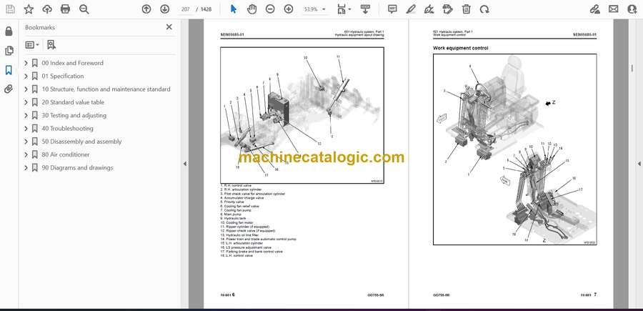
- Hydraulic equipment layout drawing
- Work equipment control
- Hydraulic tank
- Main pump
- Double type pump
- 602 Hydraulic system, Part 2
- Control valve
- CLSS
- Functions and operation by valve
- Hydraulic cylinder
- Swivel joint
- Pilot check valve
- Accumulator (for blade)
- 700 Work equipment
- Circle and drawbar
- Blade
- Lifter
- Circle rotation motor
- Circle rotation gear
- 800 Cab and its attachments
- 900 Electrical system
- Machine monitor
- Automatic shift control system
- Transmission controller
- Engine controller
- KOMTRAX system
- Starting engine circuit
- Stopping engine circuit
- Preheating circuit
- Sensor
- 20 Standard value table
- 100 Standard service value table
- Standard value table for engine
- Standard value table for machine
- 30 Testing and adjusting
- 101 Testing and adjusting, Part 1
- Precautions before work
- Tool for testing, adjusting and troubleshooting
- Sketches of special tools
- Measuring engine speed
- Measuring boost pressure
- Measuring exhaust gas temperature
- Measuring exhaust gas color
- Adjusting valve clearance
- Measuring compression pressure
- Measuring blowby pressure
- Measuring engine oil pressure
- Handling fuel system device
- Releasing remaining pressure in fuel system
- Measuring fuel pressure
- Bleeding air from fuel circuit
- Checking fuel circuit for leakage
- Handling cylinder cutout mode operation
- Handling no injection cranking operation
- Handling voltage circuit of engine controller
- Checking muffler body and muffler stack for looseness and damage
- Checking muffler function
- Check of installed condition of cylinder head and manifolds
- Checking engine piping for damage and looseness
- Testing fuel return rate and leakage
- Testing and adjusting alternator belt tension
- Testing and adjusting air conditioner compressor belt tension
- Handling high voltage circuit of engine controller
- 102 Testing and adjusting, Part 2
- Testing power train oil pressure
- Adjusting transmission speed sensor
- Retrieval of disabled machine due to transmission valve failure
- Flushing procedure for torque converter and transmission circuit
- Testing and adjusting toe-in
- Adjusting bearing preload
- Measuring and adjusting differential lockup oil pressure
- Testing and adjusting steering oil pressure
- Measuring oil leakage of steering cylinder
- Bleeding air from steering circuit
- Testing and adjusting brake oil pressure
- Releasing remaining pressure from brake circuit
- Bleeding air from brake circuit
- Testing wheel brake disc wear
- Testing and adjusting parking brake
- Parking brake emergency releasing procedure
- Charging brake accumulator with nitrogen gas
- Testing and adjusting work equipment oil pressure
- Adjusting pump PC valve
- Testing and adjusting pump LS differential pressure
- Testing lift arm lock cylinder circuit oil pressure
- Testing hydraulic fan
- Measuring oil leakage of work equipment cylinder
- Bleeding air from work equipment circuit
- Bleeding air from fan pump
- Bleeding air from fan motor
- Clearance adjustment of drawbar ball joint
- Adjusting clearance of blade circle guide
- Adjusting circle rotating gear
- Charging blade accumulator gas
- Procedure for testing diodes
- 103 Testing and adjusting, Part 3
- Special functions of machine monitor (EMMS)
- How to start KOMTRAX terminal operations
- Lamp display of KOMTRAX terminal
- Preparation work for troubleshooting of electrical system
- Pm Clinic
- 40 Troubleshooting
- 100 Failure code table and fuse locations
- Precautions before work
- Failure codes table
- Fuse locations
- 200 General Information on troubleshooting
- Points to remember when troubleshooting
- Sequence of events in troubleshooting
- Checks before troubleshooting
- Classification and procedures for troubleshooting
- Symptom and troubleshooting numbers
- Information in troubleshooting table
- Procedure for troubleshooting wiring harness of pressure sensor system for open circuit
- Connection table for connector pin numbers
- T- branch box and T- branch adapter table
- 301 Troubleshooting by failure code, Part 1
- Failure code [1500LO] TORQFLOW transmission: Double engangement
- Failure code [15F0MW] Transmission Forward clutch: Slip
- Failure code [15G0MW] Transmission Reverse clutch: Slip
- Failure code [15H0MW] Transmission H clutch: Slip
- Failure code [15J0MW] Transmission L clutch: Slip
- Failure code [15K0MW] Transmission 1st clutch: Slip
- Failure code [15L0MW] Transmission 2nd clutch: Slip
- Failure code [15M0MW] Transmission 3rd clutch: Slip
- Failure code [15N0MW] Transmission 4th clutch: Slip
- Failure code [15SAL1] ECMV F clutch: Although command signal does not flow, fill signal is output
- Failure code [15SAMA] ECMV F clutch: Malfunction
- Failure code [15SBL1] ECMV R clutch: Although command signal does not flow, fill signal is output
- Failure code [15SBMA] ECMV R clutch: Malfunction
- Failure code [15SCL1] ECMV H clutch: Although command signal does not flow, fill signal is output
- Failure code [15SCMA] ECMV H clutch: Malfunction
- Failure code [15SDL1] ECMV L clutch: Although command signal does not flow, fill signal is output
- Failure code [15SDMA] ECMV L clutch: Malfunction
- Failure code [15SEL1] ECMV 1stclutch: Although command signal does not flow, fill signal is output
- Failure code [15SEMA] ECMV 1st clutch: Malfunction
- Failure code [15SFL1] ECMV 2nd clutch: Although command signal does not flow, fill signal is output
- Failure code [15SFMA] ECMV 2nd clutch: Malfunction
- Failure code [15SGL1] ECMV 3rd clutch: Although command signal does not flow, fill signal is output
- Failure code [15SGMA] ECMV 3rd clutch: Malfunction
- Failure code [15SHL1] ECMV 4th clutch: Although command signal does not flow, fill signal is output
- Failure code [15SHMA] ECMV 4th clutch: Malfunction
- Failure code [15SJMA] ECMV lockup clutch: Malfunction
- Failure code [15U0NT] Inching clutch: Overheat
- Failure code [2G42ZG] Front accumulator: Pressure drop
- Failure code [2G43ZG] Rear accumulator: Pressure drop
- Failure code [AB00KB] Alternator: Short circuit
- Failure code [AB00L6] Alternator: Signal does not match engine running or stopped state
- Failure code [AB00MA] Alternator: Malfunction
- Failure code [B@BAZG] Engine: Oil pressure drop, engine speed derated
- Failure code [B@BCNS] Eng Water: Overheat
- Failure code [B@CENS] Torque Converter Oil: Overheat
- Failure code [B@CKNS] Differential case oil temperature: Overheat
- Failure code [B@HANS] HYD Oil Temp.: Overheat
- 302 Troubleshooting by failure code, Part 2
- Failure code [CA111] ECM Critical Internal Failure
- Failure code [CA115] Eng Ne and Bkup Speed Sens Error
- Failure code [CA122] Chg Air Press Sensor High Error
- Failure code [CA123] Chg Air Press Sensor Low Error
- Failure code [CA131] Throttle Sensor High Error
- Failure code [CA132] Throttle Sensor Low Error
- Failure code [CA135] Eng Oil Press Sensor High Error
- Failure code [CA141] Eng Oil Press Sensor Low Error
- Failure code [CA144] Coolant Temp Sens High Error
- Failure code [CA145] Coolant Temp Sens Low Error
- Failure code [CA153] Chg Air Temp Sensor High Error
- Failure code [CA154] Chg Air Temp Sensor Low Error
- Failure code [CA187] Sensor 2 Supply Volt Low Error
- Failure code [CA221] Ambient Press Sens High Error
- Failure code [CA222] Ambient Press Sens Low Error
- Failure code [CA227] Sensor 2 Supply Volt High Error
- Failure code [CA234] Eng Overspeed
- Failure code [CA238] Ne Speed Sensor Supply Volt Error
- Failure code [CA263] Fuel Temp Sensor High Error
- Failure code [CA265] Fuel Temp Sensor Low Error
- Failure code [CA271] IMV/PCV1 Short Error
- Failure code [CA272] IMV/PCV1 Open Error
- Failure code [CA273] PCV2 Short Error
- Failure code [CA274] PCV2 Open Error
- Failure code [CA322] Inj #1 (#1) Open/Short Error
- Failure code [CA323] Inj #5 (#5) Open/Short Error
- Failure code [CA324] Inj #3 (#3) Open/Short Error
- Failure code [CA325] Inj #6 (#6) Open/Short Error
- Failure code [CA331] Inj #2 (#2) Open/Short Error
- Failure code [CA332] Inj #4 (#4) Open/Short Error
- Failure code [CA342] Calibration Code Incompatibility
- Failure code [CA351] Injectors Drive Circuit Error
- Failure code [CA352] Sensor 1 Supply Volt Low Error
- Failure code [CA386] Sensor 1 Supply Volt High Error
- 303 Troubleshooting by failure code, Part 3
- Failure code [CA431] Idle Validation Sw Error
- Failure code [CA432] Idle Validation Process Error
- Failure code [CA441] Battery Voltage Low Error
- Failure code [CA442] Battery Voltage High Error
- Failure code [CA449] Rail Press Very High Error
- Failure code [CA451] Rail Press Sensor High Error
- Failure code [CA452] Rail Press Sensor Low Error
- Failure code [CA553] Rail Press High Error
- Failure code [CA554] Rail Press Sensor In Range Error
- Failure code [CA559] Rail Press Low Error
- Failure code [CA689] Eng Ne Speed Sensor Error
- Failure code [CA731] Eng Bkup Speed Sens Phase Error
- Failure code [CA757] All Continuous Data Lost Error
- Failure code [CA778] Eng Bkup Speed Sensor Error
- Failure code [CA1633] KOMNET Datalink Timeout Error
- Failure code [CA2185] Throt Sensor Sup Volt High Error
- Failure code [CA2186] Throt Sensor Sup Volt Low Error
- Failure code [CA2249] Rail Press Very Low Error
- Failure code [CA2555] Grid Htr Relay Open Circuit
- Failure code [CA2556] Intake heater relay short circuit
- 304 Troubleshooting by failure code, Part 4
- Failure code [D160KA] Backup lamp relay: Disconnection
- Failure code [D160KB] Backup lamp relay: Short circuit
- Failure code [D19KKZ] Differential lock relay: Open circuit, short circuit
- Failure code [D5ZHL6] C terminal signal: Signal does not match engine running or stopped state
- Failure code [DAFRKR] Transmission controller CAN communication: Communication error (machine monitor)
- Failure code [DAQ0KK] Transmission controller: Low source voltage (input)
- Failure code [DAQ0KT] Transmission controller: Abnormality in non-volatile memory
- Failure code [DAQ2KK] Transmission controller load power supply line: Low source voltage (input)
- Failure code [DAQ9KQ] Transmission controller model selection: Disagreement of model selection signals
- Failure code [DAQRKR] Transmission controller CAN communication: Defective communication (Abnormality in objective component system)
- Failure code [DAQRMA] Option setting for transmission controller: Malfunction
- Failure code [DB2RKR] Engine controller CAN communication: Defective communication (Abnormality in objective component system)
- Failure code [DD1PKB] RPM set switch power supply: Short circuit
- Failure code [DD1QKB] RPM set mode switch: Short circuit
- Failure code [DDB6L4] Transmission gear shift lever: Parking break signal error
- Failure code [DDTHKA] Fill switch for H clutch: Open circuit
- Failure code [DDTJKA] Fill switch for L clutch: Open circuit
- Failure code [DDTKKA] Fill switch for 1st clutch: Open circuit
- Failure code [DDTLKA] Fill switch for 2nd clutch: Open circuit
- Failure code [DDTMKA] Fill switch for 3rd clutch: Open circuit
- Failure code [DDTNKA] Fill switch for R clutch: Open circuit
- Failure code [DDTPKA] Fill switch for 4th clutch: Open circuit
- Failure code [DDTQKA] Fill switch for F clutch: Open circuit
- Failure code [DF10L4] Gear shift lever: Gear speed and travel direction signals do not match
- Failure code [DGF1KX] T/M oil temp sensor: Input signal out of range
- Failure code [DGH2KB] Hyd Oil Sensor: Short circuit
- Failure code [DGT1KX] T/C Oil Temp. Sensor: Input signal out of range
- Failure code [DJF1KA] Fuel Level Sensor: Disconnection
- Failure code [DK70KX] Inching pedal angle sensor: Input signal out of range
- Failure code [DKD0KX] Articulation angle sensor: Input signal out of range
- 305 Troubleshooting by failure code, Part 5
- Failure code [DLF1KA] Transmission input shaft speed sensor: Open circuit
- Failure code [DLF1LC] Transmission input shaft speed sensor: Speed signals disagree
- Failure code [DLF2KA] Transmission intermediate shaft speed sensor: Open circuit
- Failure code [DLF2LC] Transmission intermediate shaft speed sensor: Speed signals disagree
- Failure code [DLF3KA] Transmission intermediate shaft speed sensor (2): Open circuit
- Failure code [DLF3LC] Transmission intermediate shaft speed sensor (2): Speed signals disagree
- Failure code [DLM3LC] Fan Speed Sensor: Short circuit
- Failure code [DLT3KA] Transmission output shaft speed sensor: Open circuit
- Failure code [DV00KB] Buzzer: Short circuit
- Failure code [DW4BKA] Parking brake solenoid valve: Open circuit
- Failure code [DW4BKB] Parking brake solenoid valve: Short circuit
- Failure code [DX16KA] Fan pump EPC solenoid: Open circuit
- Failure code [DX16KB] Fan pump EPC solenoid: Short circuit
- Failure code [DX16KY] Fan pump EPC solenoid: Hot circuit
- Failure code [DXH1KA] Lockup ECNV solenoid: Open circuit
- Failure code [DXH1KB] Lockup ECMV solenoid: Short circuit
- Failure code [DXH1KY] Lockup ECMV solenoid: Hot short
- Failure code [DXH2KA] H clutch ECMV solenoid: Open circuit
- Failure code [DXH2KB] H clutch ECMV solenoid: Short circuit
- Failure code [DXH2KY] H clutch ECMV solenoid: Hot short
- Failure code [DXH3KA] L clutch ECMV solenoid: Open circuit
- Failure code [DXH3KB] L clutch ECMV solenoid: Short circuit
- Failure code [DXH3KY] L clutch ECMV solenoid: Hot short
- Failure code [DXH4KA] 1st clutch ECMV solenoid: Open circuit
- Failure code [DXH4KB] 1st clutch ECMV solenoid: Short circuit
- Failure code [DXH4KY] 1st clutch ECMV solenoid: Hot short
- Failure code [DXH5KA] 2nd clutch ECMV solenoid: Open circuit
- Failure code [DXH5KB] 2nd clutch ECMV solenoid: Short circuit
- Failure code [DXH5KY] 2ndclutch ECMV solenoid: Hot short
- Failure code [DXH6KA] 3rd clutch ECMV solenoid: Open circuit
- Failure code [DXH6KB] 3rd clutch ECMV solenoid: Short circuit
- Failure code [DXH6KY] 3rd clutch ECMV solenoid: Hot short
- Failure code [DXH7KA] R clutch ECMV solenoid: Open circuit
- Failure code [DXH7KB] R clutch ECMV solenoid: Short circuit
- Failure code [DXH7KY] R clutch ECMV solenoid: Hot short
- Failure code [DXH8KA] F clutch ECMV solenoid: Open circuit
- Failure code [DXH8KB] F clutch ECMV solenoid: Short circuit
- Failure code [DXH8KY] F clutch ECMV solenoid: Hot short
- Failure code [DXHHKA] 4th clutch ECMV solenoid: Open circuit
- Failure code [DXHHKB] 4th clutch ECMV solenoid: Short circuit
- Failure code [DXHHKY] 4th clutch ECMV solenoid: Hot short
- 400 Troubleshooting of electrical system (E-mode)
- Before carrying out troubleshooting of electrical system (E-mode)
- Information in troubleshooting table
- E-1 Engine does not start or engine is hard to start.
- E-2 Preheater does not operate
- E-3 Transmission mode does not switch
- E-4 Creep mode function does not work or is not reset.
- E-5 Differential lock function does not work or is not reset
- E-6 Performance of wheel brake is poor
- E-7 Parking brake cannot be applied or cannot be released
- E-8 Lift arm lock pin does not lock lift arm, or does not unlock it
- E-9 Blade accumulator function does not work or is not reset
- E-10 When starting switch is turned to ON position, machine monitor does not operate normally
- E-11 When starting switch is turned to ON position, display of machine monitor does not display standard screen
- E-12 When starting switch is turned to ON position, caution lamps lights up
- E-13 Emergency stop lamp lights up while engine is running
- E-14 Speedometer or engine tachometer does not indicate correctly
- E-15 Coolant temperature gauge indication is not correct
- E-16 Articulation gauge does not display normally
- E-17 Torque converter oil temperature gauge does not display normally
- E-18 Fuel gauge does not display normally
- E-19 Character display is not normal
- E-20 Centralized warning lamp does not light up or does not go off
- E-21 Alarm buzzer does not sound or does not stop sounding
- E-22 Machine monitor mode selector switch does not function
- E-23 Headlamp, clearance lamp, and tail lamp do not light up or go off.
- E-24 Front working lamp does not light up or does not go off
- E-25 Working lamp does not light up or does not go off
- E-26 Turn signal lamp and hazard lamp do not flash or go off
- E-27 Brake lamp does not light up or go off
- E-28 Backup lamp does not light up or does not go off
- E-29 Back-up alarm does not sound or does not stop
- E-30 Wipers do not operate
- E-31 Windshield washer does not operate
- E-32 Horn does not sound or does not stop sounding
- E-33 KOMTRAX system does not operate normally
- 500 Troubleshooting of hydraulic and mechanical system (H-mode)
- How to read troubleshooting matrix
- Failure mode and cause table
- H-1 Engine speed lowers significantly or engine stalls
- H-2 Machine does not start
- H-3 Gear is not shifted
- H-4 Travel lacks speed or power.
- H-5 Torque converter lockup does not work or is not released.
- H-6 Too much time lag at starting of travel or changing gear shift
- H-7 Torque converter oil temperature is high
- H-8 Differential lock-up function does not operate or can not be released
- H-9 Steering speed or power is insufficient
- H-10 Steering wheel does not move
- H-11 Wheel brake does not work at all or sufficiently
- H-12 Wheel brake cannot be released or drags
- H-13 Parking brake does not work at all or insufficiently
- H-14 Parking brake (including emergency release system) cannot be released or drags.
- H-15 All work equipment operation lacks speed or power.
- H-16 Work equipment does not work at all
- H-17 Unusual noise comes out from around hydraulic pump
- H-18 Blade lift operation lacks speed or power
- H-19 Hydraulic drift of lifted blade is large
- H-20 Drawbar side shift operation lacks speed or power
- H-21 Blade side shift operation lacks speed or power
- H-22 Power tilt operation lacks speed or power
- H-23 Articulate operation lacks speed or power
- H-24 Leaning operation lacks speed or power
- H-25 Hydraulic drift of leaning cylinders (leaning) is large
- H-26 Blade does not rotate
- H-27 Lift arm lock pin does not lock lift arm, or does not unlock it
- H-28 Blade accumulator function does not work or is not reset
- H-29 Fan revolution is abnormal (Fan sound/vibration is abnormally large or engine overheats)
- 600 Troubleshooting of engine (S-mode)
- Method of using troubleshooting chart
- S-1 Startability is poor
- S-2 Engine does not start
- S-3 Engine does not pick up smoothly
- S-4 Engine stops during operation
- S-5 Engine does not run smoothly
- S-6 Engine lacks power
- S-7 Exhaust smoke is black (incomplete combustion)
- S-8 Oil consumption is excessive (or exhaust smoke is blue)
- S-9 Oil becomes contaminated early
- S-10 Fuel consumption is excessive
- S-11 Oil is in coolant (or coolant spurts or coolant level goes down)
- S-12 Oil pressure drops
- S-13 Oil level rises (coolant or fuel in oil).
- S-14 Coolant temperature rises too high (overheating)
- S-15 Unusual noise is made
- S-16 Vibration is excessive
- 50 Disassembly and assembly
- 100 General information on disassembly and assembly
- Precautions before work
- How to read this manual
- Coating materials list
- Special tools list
- Sketches of special tools
- 200 Engine and cooling system
- Removal and installation of fuel supply pump assembly
- Removal and installation of fuel injector assembly
- Removal and installation of cylinder head assembly
- Removal and installation of engine front oil seal
- Removal and installation of engine rear oil seal
- Removal and installation of cooling system assembly
- Removal and installation of radiator assembly
- Removal and installation of power train oil cooler assembly
- Removal and installation of aftercooler assembly
- Removal and installation of cooling fan oil cooler assembly
- Removal and installation of air conditioner condenser assembly
- Removal and installation of cooling fan and fan motor assembly
- Removal and installation of engine, torque converter, and transmission assembly
- Disconnection and connection of engine, torque converter, and transmission assembly
- Removal and installation of engine hood assembly
- Removal and installation of fuel tank assembly
- 300 Power train
- Disassembly and assembly of torque converter and transmission assembly
- Disassembly and assembly of transmission clutch assembly
- Disassembly and assembly of torque converter assembly
- Removal and installation of tandem drive and final drive assembly
- Disassembly and assembly of tandem drive assembly
- Disassembly and assembly of final drive assembly
- 400 Brake system
- Disassembly and assembly of wheel brake assembly
- 500 Undercarriage and frame
- Removal and installation of center hinge pin
- 600 Hydraulic system
- Removal and installation of hydraulic tank assembly
- Disassembly and assembly of hydraulic cylinder assembly
- 700 Work equipment
- Removal and installation of blade assembly
- Removal and installation of ripper assembly
- Removal and installation of circle rotation gear assembly
- Disassembly and assembly of circle rotation gear assembly
- Removal and installation of circle drawbar assembly
- 800 Cab and its attachments
- Removal and installation of operator's cab assembly
- Removal and installation of operator's cab glass (adhered glass)
- Removal and installation of floor frame assembly
- Removal and installation of air conditioner unit assembly
- 900 Electric system
- Removal and installation of machine monitor assembly
- Removal and installation of engine controller assembly
- Removal and installation of transmission controller assembly
- Removal and installation of KOMTRAX terminal assembly
- 80 Air conditioner
- 100 Air conditioner
- Precautions before work
- Precautions for refrigerant
- Air Conditioner Components
- Structure and Function of Refrigeration System
- Overview of Refrigeration System
- Circuit diagram of refrigerant
- Air Conditioner Unit
- Compressor
- Condenser
- Receiver
- Air conditioner control panel
- Procedure for check and troubleshooting
- Circuit diagram and layout of connector pins
- System diagram
- Detail of air conditioner unit
- Parts and connectors layout
- Testing air leakage (ducts)
- Check with self-diagnosis (control panel display)
- Testing temperature control
- Testing FRESH/RECIRC air changeover
- Testing evaporator temperature sensor
- Testing relays
- Testing blower amp
- Troubleshooting Chart 1
- Troubleshooting Chart 2
- Information in troubleshooting table
- Troubleshooting for power supply system (Air conditioner does not operate)
- Troubleshooting of compressor and refrigerant system (Air is not cooled)
- Troubleshooting for blower motor system (Air does not come out or air flow is improper)
- Troubleshooting for temperature control
- Troubleshooting for FRESH/RECIRC air changeover
- Troubleshooting with gauge pressure
- Connection of service tool
- Precautions for disconnecting and connecting air conditioner piping
- Handling compressor oil
- 90 Diagrams and drawings
- 100 Hydraulic diagrams and drawings
- Power train hydraulic circuit diagram
- Hydraulic circuit diagram of differential lock
- Hydraulic circuit diagram
- 200 Electrical diagrams and drawings
- Electrical circuit diagram
- Connector list and stereogram
Komatsu


