The Komatsu D155A-6 Crawler Dozer Shop Manual (SEN02854-30) is meant for doing real repair work on a mid-size production dozer, not just daily checks. This kind of machine is pushing, ripping, and working slopes all day, so when it’s down, the clock’s burning money. The people who usually reach for this manual are field techs, shop mechanics, and anyone pulling wrenches on undercarriage, powertrain, engine, or hydraulics. They’re trying to diagnose faults, strip and rebuild components, and get the machine back in the dirt without guesswork.
What this manual helps you do
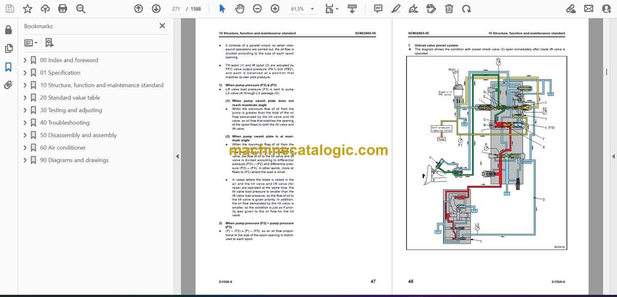
- Trace hydraulic issues on the D155A-6 using circuit layouts and step-by-step testing procedures.
- Diagnose engine and powertrain problems with guided checks, symptom-based charts, and proper disassembly sequences.
- Follow correct teardown and reassembly order for major components like finals, steering, and blade controls.
- Verify adjustments on linkages, brakes, and steering so the dozer tracks straight and responds properly under load.
- Handle electrical faults by following wiring diagrams and standard test routines with a basic meter and test light.
Who this is for
This is a shop-level Komatsu D155A-6 Crawler Dozer Shop Manual for people actually repairing and rebuilding machines. If you’re just operating or doing basic daily service, you probably want the Operation & Maintenance manual instead of SEN02854-30.
FAQ
Q: Is this a PDF I can download and search or print?
A: Yes, it’s a PDF you can download, search by keyword, and print the pages you need for the jobsite.
Q: Does it go deep enough for full rebuilds, or is it just light service?
A: It’s written for workshop repairs, so you’ll see what you’d normally expect for diagnostics, disassembly, inspection, and reassembly.
Q: How do I know if it matches my serial number or variant?
A: Check your machine plate and make sure your D155A-6 and coverage match the SEN02854-30 reference before you buy.
Bottom line: if you’re repairing or overhauling a Komatsu D155A-6 in the field or shop, this is the right manual; if you only need operating tips and daily checks, keep looking.
📘 Show Index
Table of Contents:
- 00 Index and foreword
- Index
- Composition of shop manual
- Table of contents
- Foreword and general information
- Safety notice
- How to read the shop manual
- Explanation of terms for maintenance standard
- Handling of electric equipment and hydraulic component
- Handling of connectors newly used for engines
- How to read electric wire code
- Precautions when carrying out operation
- Method of disassembling and connecting push-pull type coupler
- Standard tightening torque table
- Conversion table
- 01 Specification
- Specification and technical data
- Specification dimension drawings
- Specifications
- Weight table
- Table of fuel, coolant and lubricants
- 10 Structure, function and maintenance standard
- Engine and cooling system
- Radiator, oil cooler
- Engine mount
- Cooling fan pump
- Cooling fan motor
- Power train, Part 1
- Power train skeleton
- Overall drawing of power train unit
- Power train hydraulic piping drawing
- Damper, universal joint
- Torque converter, PTO
- Transmission
- Transmission ECMV
- Main relief valve and torque converter relief valve
- Lubricating oil relief valve
- Scavenging pump
- Power train and steering lubrication pump
- Power train, Part 2
- Work equipment pump
- Work equipment cooler bypass valve
- Steering, brake control
- Steering unit
- Steering control valve
- Steering clutch ECMV, steering brake ECMV
- Parking brake solenoid valve
- Sudden stop prevention valve
- Final drive
- Sprocket
- Undercarriage and frame
- Track frame
- Recoil spring
- Idler
- Track roller
- Carrier roller
- Track shoe
- Main frame
- Suspension
- Hydraulic system
- Work equipment hydraulic piping diagram
- Work equipment control piping diagram
- Work equipment control
- Hydraulic tank and filter
- Accumulator
- PPC valve
- Work equipment lock valve
- Control valve
- Work equipment cylinder
- Piston valve
- Quick drop valve
- Self pressure reducing valve
- Work equipment
- Cylinder stay
- Blade
- Ripper
- Cutting edge, end bit
- Cab and its attachments
- Cab mount + ROPS pin
- ROPS cab
- ROPS floor
- Air conditioner
- Electrical system
- Engine control
- Engine control system
- Deceleration potentiometer
- Monitor system
- Sensors
- Palm command control system
- KOMTRAX system
- 20 Standard value table
- Standard service value table
- Standard value table for engine
- Standard value table for machine
- 30 Testing and adjusting
- Testing and adjusting, Part 1
- Tools for testing, adjusting, and troubleshooting
- Sketches of special tools
- Measuring engine speed
- Measuring intake air pressure (boost pressure)
- Measuring exhaust temperature
- Measuring exhaust gas color
- Adjusting valve clearance
- Measuring compression pressure
- Measuring blow-by pressure
- Measuring engine oil pressure
- Handling fuel system parts
- Releasing residual pressure from fuel system
- Measuring fuel pressure
- Measuring fuel return rate and fuel leakage
- Bleeding air from fuel circuit
- Measuring fuel circuit for leakage
- Testing and adjusting alternator belt tension
- Testing and adjusting air conditioner compressor belt tension
- Measuring fan speed
- Measuring fan circuit oil pressure
- Bleeding air from fan pump
- Bleeding air from work equipment pump
- Adjusting fuel control dial and decelerator pedal
- Testing and adjusting, Part 2
- Measuring power train oil pressure
- Adjusting transmission output shaft speed sensor
- Simple test procedure for brake performance
- Adjusting brake pedal
- Adjusting parking brake lever
- Emergency escape method when power train has trouble
- Adjusting idler clearance
- Testing and adjusting track shoe tension
- Measuring and adjusting work equipment oil pressure
- Measuring control circuit basic pressure
- Measuring work equipment lock solenoid valve output pressure (PPC valve basic pressure)
- Measuring PPC valve output pressure
- Adjusting work equipment PPC valve play
- Measuring ripper pin puller solenoid valve output pressure
- Testing parts which cause hydraulic drift of blade and ripper
- Measuring internal leakage of work equipment cylinder
- Releasing residual pressure from work equipment cylinder
- Bleeding air from work equipment cylinder
- Adjusting work equipment lock lever
- Adjusting blade
- Testing and adjusting play of blade electric lever
- Adjusting operator's cab
- Testing and adjusting, Part 3
- Special functions of machine monitor (EMMS)
- Testing and adjusting, Part 4
- Handling of power supply circuit of engine controller
- Preparation work for troubleshooting of electrical system
- Pm Clinic
- 40 Troubleshooting
- Failure code table and fuse locations
- Failure codes table
- Fuse locations
- General information on troubleshooting
- Points to remember when troubleshooting
- Sequence of events in troubleshooting
- Check before troubleshooting
- Checking water pump for water leakage
- Classification and procedures for troubleshooting
- Information in troubleshooting table
- Connection table for connector pin numbers
- T- branch box and T- branch adapter table
- Troubleshooting by failure and error codes, Part 1
- Failure code [1500L0]
- Failure code [15SAL1]
- Failure code [15SALH]
- Failure code [15SBL1]
- Failure code [15SBLH]
- Failure code [15SEL1]
- Failure code [15SELH]
- Failure code [15SFL1]
- Failure code [15SFLH]
- Failure code [15SGL1]
- Failure code [15SGLH]
- Failure code [2201L1]
- Failure code [2201LH]
- Failure code [2202L1]
- Failure code [2202LH]
- Failure code [2300KM]
- Failure code [2301L1]
- Failure code [2301LH]
- Failure code [2302L1]
- Failure code [2302LH]
- Failure code [7RFAKA]
- Failure code [AA10NX]
- Failure code [AB00MA]
- Failure code [B@BAZG]
- Failure code [B@BCNS]
- Failure code [B@BCZK]
- Failure code [B@CENS]
- Failure code [B@HANS]
- Failure code [CA111]
- Failure code [CA115]
- Failure code [CA122]
- Failure code [CA123]
- Failure code [CA131]
- Failure code [CA132]
- Failure code [CA135]
- Failure code [CA141]
- Failure code [CA144]
- Failure code [CA145]
- Failure code [CA153]
- Failure code [CA154]
- Failure code [CA187]
- Failure code [CA221]
- Failure code [CA222]
- Failure code [CA227]
- Troubleshooting by failure and error codes, Part 2
- Failure code [CA234]
- Failure code [CA238]
- Failure code [CA263]
- Failure code [CA265]
- Failure code [CA271]
- Failure code [CA272]
- Failure code [CA273]
- Failure code [CA274]
- Failure code [CA322]
- Failure code [CA323]
- Failure code [CA324]
- Failure code [CA325]
- Failure code [CA331]
- Failure code [CA332]
- Failure code [CA342]
- Failure code [CA351]
- Failure code [CA352]
- Failure code [CA386]
- Failure code [CA441]
- Failure code [CA442]
- Failure code [CA449]
- Failure code [CA451]
- Failure code [CA452]
- Failure code [CA553]
- Failure code [CA554]
- Failure code [CA559]
- Failure code [CA689]
- Failure code [CA731]
- Failure code [CA757]
- Failure code [CA778]
- Failure code [CA1633]
- Failure code [CA2185]
- Failure code [CA2186]
- Failure code [CA2249]
- Failure code [CA2555]
- Failure code [CA2556]
- Failure code [D110KA]
- Failure code [D110KB]
- Failure code [D130KA]
- Failure code [D130KB]
- Failure code [D161KA]
- Failure code [D161KB]
- Failure code [D190KA]
- Failure code [D190KB]
- Troubleshooting by failure and error codes, Part 3
- Failure code [D5ZKKX]
- Failure code [DAFRKR]
- Failure code [DAFRMC]
- Failure code [DB2RKR]
- Failure code [DB90KR]
- Failure code [DBE0KK]
- Failure code [DBE0KT]
- Failure code [DBE6KK]
- Failure code [DBE7KK]
- Failure code [DBE9KQ]
- Failure code [DD12KA]
- Failure code [DD12KB]
- Failure code [DD13KA]
- Failure code [DD13KB]
- Failure code [DD14KA]
- Failure code [DD14KB]
- Failure code [DDDDKA]
- Failure code [DDDDKB]
- Failure code [DDDDKX]
- Failure code [DGT1KA]
- Failure code [DGT1KX]
- Failure code [DH21KA]
- Failure code [DH21KB]
- Failure code [DK10KX]
- Failure code [DK30KA]
- Failure code [DK30KB]
- Failure code [DK30KX]
- Failure code [DK30KZ]
- Failure code [DK30L8]
- Failure code [DK31KA]
- Failure code [DK31KB]
- Failure code [DK40KA]
- Failure code [DK40KB]
- Failure code [DK55KX]
- Failure code [DK55KZ]
- Failure code [DK55L8]
- Failure code [DK56KA]
- Failure code [DK56KB]
- Troubleshooting by failure and error codes, Part 4
- Failure code [DK57KA]
- Failure code [DK57KB]
- Failure code [DKH1KA]
- Failure code [DKH1KB]
- Failure code [DLT3KA]
- Failure code [DLT3KB]
- Failure code [DW7BKA]
- Failure code [DW7BKB]
- Failure code [DWN3KA]
- Failure code [DWN3KB]
- Failure code [DWN3KY]
- Failure code [DWN5KA]
- Failure code [DWN5KB]
- Failure code [DXH4KA]
- Failure code [DXH4KB]
- Failure code [DXH4KY]
- Failure code [DXH5KA]
- Failure code [DXH5KB]
- Failure code [DXH5KY]
- Failure code [DXH6KA]
- Failure code [DXH6KB]
- Failure code [DXH6KY]
- Failure code [DXH7KA]
- Failure code [DXH7KB]
- Failure code [DXH7KY]
- Failure code [DXH8KA]
- Failure code [DXH8KB]
- Failure code [DXH8KY]
- Failure code [DXH9KA]
- Failure code [DXH9KB]
- Failure code [DXH9KY]
- Failure code [DXHAKA]
- Failure code [DXHAKB]
- Failure code [DXHAKY]
- Failure code [DXHBKA]
- Failure code [DXHBKB]
- Failure code [DXHBKY]
- Failure code [DXHCKA]
- Failure code [DXHCKB]
- Failure code [DXHCKY]
- Failure code [DXJ4KA]
- Failure code [DXJ4KB]
- Troubleshooting of electrical system (E-mode)
- Before carrying out troubleshooting for electrical system
- Information in troubleshooting table
- E-1 When starting switch turned ON, machine monitor displays nothing
- E-2 When starting switch turned ON (before starting engine), basic check item lights up
- E-3 Engine does not start (Engine does not turn)
- E-4 Preheater does not operate
- E-5 Precaution item lights up while engine is running
- E-6 Emergency stop item lights up while engine is running
- E-7 Engine coolant temperature gauge does not indicate normally
- E-8 Fuel level gauge does not indicate normally
- E-9 Power train oil temperature gauge (multi-gauge) does not indicate normally
- E-10 Hydraulic temperature gauge (multi-gauge) does not indicate normally
- E-11 Contents of display by machine monitor are different from applicable machine
- E-12 Machine monitor does not display some items
- E-13 Function switch does not work
- E-14 Operation mode does not change
- E-15 Gearshift mode does not change
- E-16 Customize function does not operate normally
- E-17 Customize memory function does not normally
- E-18 Alarm buzzer cannot be stopped
- E-19 Air conditioner does not operate normally (including air conditioner fault history)
- E-20 When starting switch is turned OFF, service meter is not displayed
- E-21 Machine monitor cannot be set in service mode
- E-22 Ripper pin puller cylinder does not operate
- E-23 Backup alarm does not sound or does not stop
- E-24 Headlamp, rear lamp, and ripper point lamp do not light up
- E-25 Windshield wiper and window washer do not operate
- E-26 KOMTRAX terminal does not operate normally
- E-27 Fan does not reverse
- E-28 Gear cannot be shifted
- E-29 Electric priming pump does not operate or does not stop automatically
- Troubleshooting of hydraulic and mechanical system (H-mode)
- Information in troubleshooting table
- H-1 Power is low (Drawbar pull is low)
- H-2 Machine does not travel (at 2nd or 3rd gear speed)
- H-3 Machine does not start at any gear speed
- H-4 Machine can travel only forward or in reverse
- H-5 When gear speed or travel direction is changed, time lag is large
- H-6 Steering is not possible
- H-7 Steering is possible only on one side
- H-8 Steering overrun occurs
- H-9 Brake does not work
- H-10 Power train oil is overheated
- H-11 Speed of all work equipment is low
- H-12 No work equipment moves
- H-13 Blade lift speed or power is low
- H-14 Blade tilt speed or power is low
- H-15 Ripper lift speed or power is low
- H-16 Ripper tilt speed or power is low
- H-17 Hydraulic drift of blade lift is large
- H-18 Hydraulic drift of blade tilt is large
- H-19 Hydraulic drift of ripper lift is large
- H-20 Ripper pin puller cylinder does not operate
- H-21 Abnormal sound comes out from around work equipment pump
- H-22 Fan speed is abnormal (Sound and/or vibration are abnormally large or engine over heats)
- Troubleshooting of engine (S-mode)
- Method of using troubleshooting chart
- S-1 Starting performance of engine is poor
- S-2 Engine does not start
- S-3 Engine does not pick up smoothly
- S-4 Engine stops during operation
- S-5 Engine does not rotate smoothly
- S-6 Engine lack output (or lacks power)
- S-7 Exhaust gas is black (incomplete combustion)
- S-8 Oil consumption is excessive (or exhaust gas is blue)
- S-9 Oil becomes dirty quickly
- S-10 Fuel consumption is excessive
- S-11 Oil is in coolant (or coolant spurts back or coolant level goes down)
- S-12 Oil pressure drops
- S-13 Oil level rises (Entry of coolant or fuel)
- S-14 Coolant temperature becomes too high (Overheating)
- S-15 Abnormal noise is made
- S-16 Vibration is excessive
- S-17 Air cannot be bled from fuel circuit
- 50 Disassembly and assembly
- General information on disassembly and assembly
- How to read this manual
- Coating materials list
- Special tool list
- Sketches of special tools
- Engine and cooling system
- Removal and installation of fuel supply pump assembly
- Removal and installation of fuel injector assembly
- Removal and installation of cylinder head assembly
- Removal and installation of radiator assembly
- Removal and installation of aftercooler assembly
- Removal and installation of engine assembly
- Removal and installation of engine hood assembly
- Removal and installation of engine front seal
- Removal and installation of engine rear seal
- Removal and installation of fuel tank assembly
- Removal and installation of fan drive assembly
- Removal and installation of fan motor assembly
- Power train, Part 1
- Removal and installation of damper assembly
- Disassembly and assembly of damper assembly
- Removal and installation of power train unit assembly
- Disconnection and connection of power train unit assembly
- Power train, Part 2
- Disassembly and assembly of PTO assembly
- Disassembly and assembly of torque converter assembly
- Disassembly and assembly of transmission assembly
- Disassembly and assembly of steering case assembly
- Power train, Part 3
- Removal and installation of final drive assembly
- Disassembly and assembly of final drive assembly
- Undercarriage and frame
- Removal and installation of track frame assembly
- Removal and installation of idler assembly
- Disassembly and assembly of idler assembly
- Removal and installation of recoil spring assembly
- Disassembly and assembly of recoil spring assembly
- Removal and installation of track roller assembly
- Disassembly and assembly of track roller assembly
- Removal and installation of 1st bogie assembly
- Removal and installation of 2nd, 3rd, and 4th bogie assemblies
- Disassembly and assembly of bogie assembly
- Removal and installation of carrier roller assembly
- Disassembly and assembly of carrier roller assembly
- Removal and installation of pivot shaft assembly
- Spreading and installation of track shoe assembly
- General disassembly and assembly of track shoe
- Disassembly and assembly of 1 link in field
- Disassembly and assembly of master link
- Removal and installation of equalizer bar assembly
- Disassembly and assembly of equalizer bar assembly
- Removal and installation of segment teeth
- Hydraulic system
- Removal and installation of hydraulic tank assembly
- Removal and installation of hydraulic pump assembly
- Disassembly and assembly of hydraulic cylinder assembly
- Work equipment
- Removal and installation of blade assembly
- Removal and installation of blade lift cylinder assembly
- Disassembly and assembly of multi-shank ripper
- Cab and its attachments
- Removal and installation of operator's cab assembly
- Removal and installation of operator's cab glass (Stuck glass)
- Removal and installation of operator's cab and floor frame assembly
- Electrical system
- Removal and installation of air conditioner unit assembly
- Removal and installation of engine controller assembly
- Removal and installation of power train controller assembly
- Removal and installation of KOMTRAX assembly
- 60 Air conditioner
- Structure, function, testing, adjusting, and troubleshooting
- Structure and function
- Air conditioner component
- Configuration and function of refrigerating cycle
- Outline of refrigerating cycle
- Air conditioner unit
- Functions of major components in the air conditioner unit
- Control plate
- Compressor
- Condenser
- Receiver drier
- Testing, adjusting and troubleshooting
- Caution about refrigerant
- Troubleshooting procedure
- Basic flow of troubleshooting
- Block diagram
- Circuit diagram and arrangement of connector pins
- Detail of air conditioner unit
- Part and connector locations
- Testing air leakage (duct)
- Testing with self-diagnosis function
- Testing temperature control
- Testing vent (mode) changeover
- Testing Recirc/Fresh changeover
- Testing inner sensor
- Testing evaporator temperature sensor
- Testing sunlight sensor
- Testing (dual) pressure switch for refrigerant
- Testing relays and diodes
- Troubleshooting chart 1
- Troubleshooting chart 2
- Troubleshooting for electrical system (E mode)
- E-1 Power supply system (Air conditioner does not operate)
- E-2 Compressor system (Air is not cooled)
- E-3 Blower motor system (No air comes out or air flow is abnormal)
- E-4 Temperature cannot be controlled
- E-5 Vent (mode) cannot be changed over
- E-6 Recirc/Fresh air cannot be changed over
- Troubleshooting with gauge pressure
- Connection of service tool
- Precautions for connecting air conditioner piping
- Handling of compressor oil
- 1. Control of compressor oil
- 2. Adding of compressor oil
- 3. Compressor replacement
- 4. Applying compressor oil for O-ring
- 90 Diagrams and drawings
- Hydraulic diagrams and drawings
- Power train hydraulic circuit diagram
- Hydraulic circuit diagram Serial No.: 85001 – 85024
- Hydraulic circuit diagram Serial No.: 85025 and up
- Electrical diagrams and drawings
- Electrical circuit diagram
- Electrical circuit diagram for inside cab
- Connector/electrical wiring connection table
- Wiring harness diagram
Komatsu


