These Komatsu PC650LC-8E0, PC700LC-8E0 Crawler Excavators are big production machines used for quarry work, heavy earthmoving, and bulk excavation where downtime gets expensive fast. The people who usually reach for a shop manual like SEN05377-18 are dealer techs, independent heavy equipment mechanics, and in-house fleet shops. They’re trying to do real repairs: engine work, swing issues, hydraulic faults, structural repairs, not just fluid changes. If you’re trying to understand not just what to do but why Komatsu wants it done a certain way, this is the type of book you want.
What this manual helps you do
- Trace hydraulic problems through the main circuits, from pumps to control valves to actuators, using system layouts and step-by-step test sequences.
- Diagnose electrical and electronic faults on the machine control and monitoring systems using wiring diagrams and guided checks.
- Follow correct disassembly and reassembly procedures for major components like the upper structure, undercarriage assemblies, and work equipment.
- Check adjustment procedures for things like swing, travel, and implement functions so the machine behaves the way the factory intended.
- Handle engine, cooling, and fuel system repairs at workshop level, including common failure modes I’ve seen students miss, like contamination paths and incorrect re-priming.
Who this is for
This shop manual is aimed at field technicians, shop mechanics, and serious trainees working on Komatsu PC650LC-8E0 and PC700LC-8E0 crawler excavators. If you’re an operator just wanting basic controls and daily checks, you’d be better off with the Operation & Maintenance Manual instead.
FAQ
Q: Is this a searchable, printable PDF?
A: Yes, this is a PDF shop manual you can view on a laptop or tablet, search by keyword, and print pages for use in the bay.
Q: Is this deep enough for full overhauls, or just basic service?
A: The Shop Manual for Komatsu PC650LC-8E0, PC700LC-8E0 Crawler Excavator walks through diagnostic procedures, disassembly sequences, and reference data used during workshop-level repairs. It’s meant for full troubleshooting and rebuild work, not just routine maintenance.
Q: How do I know if it matches my exact machine variant?
A: You’ll want to match your machine model and serial tag against Komatsu’s book reference SEN05377-18; if your dealer lists this book number for your unit, this is the right manual.
Bottom line: if you’re repairing or teaching others to repair PC650LC-8E0 or PC700LC-8E0 machines at a shop or field level, this is the manual you want; if you just need operating tips or basic service intervals, keep looking for the O&M book instead.
📘 Show Index
Table of Contents:
- 00 Index and foreword
- Table of Contents
- Foreword and general information
- Safety notice
- How to read the shop manual
- Explanation of terms for maintenance standard
- Handling of hydraulic components
- Method of disconnecting and connecting push-pull type coupler
- Handling of electric equipment
- How to read electric wire code
- Precautions when performing work
- Standard tightening torque table
- List of abbreviation
- Conversion table
- 01 Specification
- Contents
- Specifications
- Specifications drawing
- Working range drawings
- Specifications
- Table of weight
- Table of fuel, coolant and lubricants
- 10 Structure and function
- Contents
- Engine and cooling system
- Engine related parts
- PTO
- Cooling system
- Power train system
- Power train
- Swing circle
- Swing machinery
- Final drive
- Undercarriage and frame
- Track frame and idler cushion
- Hydraulic system
- Hydraulic component layout
- Valve control
- Hydraulic tank and filter
- Hydraulic pump (piston pump)
- Cooling fan pump
- Cooling fan motor
- Control valve
- Swing motor
- Travel motor
- PPC valve
- Solenoid valve
- PPC shuttle valve
- Boom drift prevention valve
- Boom LOWER regeneration valve
- Arm regeneration valve
- Quick return valve
- Line oil filter
- Center swivel joint
- Accumulator
- Electrical system
- Engine control
- Electrical control system
- Monitor system
- KOMTRAX system
- Sensors
- 20 Standard value table
- Contents
- Standard value table
- Standard value table for engine
- Standard value table for machine
- 30 Testing and adjusting
- Contents
- Tool for testing, adjusting and troubleshooting
- Tools for testing, adjusting, and troubleshooting
- Engine and cooling system
- Testing engine speed
- Testing intake air pressure (boost pressure)
- Testing exhaust gas temperature
- Testing exhaust gas color
- Testing and adjusting valve clearance
- Testing compression pressure
- Testing blowby pressure
- Testing engine oil pressure
- Testing EGR valve and bypass valve drive pressure
- Handling fuel system parts
- Releasing remaining pressure from fuel system
- Testing fuel pressure
- Cylinder cut-out test mode
- No-injection cranking
- Testing fuel return rate and leakage
- Bleeding air from fuel circuit
- Testing fuel circuit for leakage
- Testing and adjusting alternator belt tension
- Testing and adjusting air conditioner compressor belt tension
- Undercarriage and frame
- Testing swing circle bearing clearance
- Checking and adjusting track tension
- Hydraulic system
- Testing and adjusting oil pressure in work equipment, swing and travel circuits
- Testing and adjusting control circuit oil pressure
- Testing and adjusting control oil pressure of piston pump
- Testing servo piston movement
- Testing PPC valve output pressure
- Testing output pressure of solenoid valve and PPC shuttle valve
- Adjusting play of work equipment and swing PPC vavles
- Isolating the parts causing hydraulic drift in work equipment
- Testing and adjusting travel deviation
- Testing fan speed
- Testing fan circuit oil pressure
- Releasing remaining pressure from hydraulic circuit
- Testing oil leakage
- Bleeding air from each part
- Electrical system
- Special functions of machine monitor
- Handling of voltage circuit of engine controller
- Preparatory work for troubleshooting of electrical system
- Inspection procedure of diode
- Pm clinic
- Pm Clinic service
- UNDERCARRIAGE INSPECTION REPORT
- 40 Troubleshooting
- Contents
- General information on troubleshooting
- Points to remember when troubleshooting
- Sequence of events in troubleshooting
- Checks before troubleshooting
- Classification and procedures for troubleshooting
- Failure codes table
- Symptom and troubleshooting numbers
- Information in troubleshooting table
- Troubleshooting method for open circuit in wiring harness of pressure sensor system
- Connector list and layout
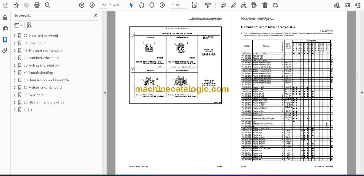
- Connection table for connector pin numbers
- T- branch box and T- branch adapter table
- Fuse locations
- Troubleshooting by failure code
- Failure code [989L00] Engine Controller Lock Caution 1
- Failure code [989M00] Engine Controller Lock Caution 2
- Failure code [989N00] Engine Controller Lock Caution 3
- Failure code [AA10NX] Air Cleaner Clogging
- Failure code [AB00KE] Charge Voltage Low
- Failure code [B@BAZG] Eng Oil Press Low
- Failure code [B@BAZK] Eng Oil Level Low
- Failure code [B@BCNS] Eng Water Overheat
- Failure code [B@BCZK] Eng Water Level Low
- Failure code [B@HANS] Hyd Oil Overheat
- Failure code [CA111] ECM Critical Internal Failure
- Failure code [CA115] Eng Ne and Bkup Speed Sens Error
- Failure code [CA122] Chg Air Press Sensor High Error
- Failure code [CA123] Chg Air Press Sensor Low Error
- Failure code [CA131] Throttle Sensor High Error
- Failure code [CA132] Throttle Sensor Low Error
- Failure code [CA135] Eng Oil Press Sensor High Error
- Failure code [CA141] Eng Oil Press Sensor Low Error
- Failure code [CA144] Coolant Temp Sens High Error
- Failure code [CA145] Coolant Temp Sens Low Error
- Failure code [CA153] Chg Air Temp Sensor High Error
- Failure code [CA154] Chg Air Temp Sensor Low Error
- Failure code [CA187] Sens Supply 2 Volt Low Error
- Failure code [CA221] Ambient Press Sens High Error
- Failure code [CA222] Ambient Press Sens Low Error
- Failure code [CA227] Sens Supply 2 Volt High Error
- Failure code [CA234] Eng Overspeed
- Failure code [CA238] Ne Speed Sens Supply Volt Error
- Failure code [CA263] Fuel Temp Sensor High Error
- Failure code [CA265] Fuel Temp Sensor Low Error
- Failure code [CA271] IMV/PCV1 Short Error
- Failure code [CA272] IMV/PCV1 Open Error
- Failure code [CA273] PCV2 Short Error
- Failure code [CA274] PCV2 Open Error
- Failure code [CA322] Inj #1(L#1) Open/Short Error
- Failure code [CA323] Inj #5 (L#5) Open/Short Error
- Failure code [CA324] Inj #3(L#3) Open/Short Error
- Failure code [CA325] Inj #6 (L#6) Open/Short Error
- Failure code [CA331] Inj #2(L#2) Open/Short Error
- Failure code [CA332] Inj #4 (L#4) Open/Short Error
- Failure code [CA342] Calibration Code Incompatibility
- Failure code [CA351] Injectors Drive Circuit Error
- Failure code [CA352] Sens Supply 1 Volt Low Error
- Failure code [CA386] Sens Supply 1 Volt High Error
- Failure code [CA441] Battery Voltage Low Error
- Failure code [CA442] Battery Voltage High Error
- Failure code [CA449] Rail Press Very High Error
- Failure code [CA451] Rail Press Sensor High Error
- Failure code [CA452] Rail Press Sensor Low Error
- Failure code [CA553] Rail Press High Error
- Failure code [CA554] Rail Press Sensor In Range Error
- Failure code [CA559] Supply Pump Press Low Error 1
- Failure code [CA689] Eng Ne Speed Sensor Error
- Failure code [CA731] Eng Bkup Speed Sens Phase Error
- Failure code [CA757] All Continuous Data Lost Error
- Failure code [CA778] Eng Bkup Speed Sensor Error
- Failure code [CA1228] EGR Valve Servo Error 1
- Failure code [CA1625] EGR Valve Servo Error 2
- Failure code [CA1626] BP Valve Sol Current High Error
- Failure code [CA1627] BP Valve Sol Current Low Error
- Failure code [CA1628] Bypass Valve Servo Error 1
- Failure code [CA1629] Bypass Valve Servo Error 2
- Failure code [CA1631] BP Valve Pos Sens High Error
- Failure code [CA1632] BP Valve Pos Sens Low Error
- Failure code [CA1633] KOMNET Datalink Timeout Error
- Failure code [CA2185] Throt Sens Sup Volt High Error
- Failure code [CA2186] Throt Sens Sup Volt Low Error
- Failure code [CA2249] Rail Press Very Low Error
- Failure code [CA2271] EGR Valve Pos Sens High Error
- Failure code [CA2272] EGR Valve Pos Sens Low Error
- Failure code [CA2351] EGR Valve Sol Current High Error
- Failure code [CA2352] EGR Valve Sol Current Low Error
- Failure code [CA2555] Grid Htr Relay Open Circuit Error
- Failure code [CA2556] Grid Htr Relay Short Circuit Error
- Failure code [D110KB] Battery Relay Drive Short Circuit
- Failure code [D163KB] Flash Light Relay Short Circuit
- Failure code [D195KA] Step Light Relay Open Circuit
- Failure code [D195KB] Step Light Relay Short Circuit
- Failure code [D19JKZ] Personal code relay abnormality
- Failure code [D862KA] GPS Antenna Open Circuit
- Failure code [DA22KK] Pump Solenoid Power Low Error
- Failure code [DA25KP] 5V Sensor1 Power Abnormality
- Failure code [DA29KQ] Model Selection Abnormality
- Failure code [DA2RMC] CAN Discon (Pump Con Detected)
- Failure code [DA80MA] Auto. Lub. Abnormal.
- Failure code [DAF8KB] Camera Power Supply Short Circuit
- Failure code [DAFGMC] GPS Module Error
- Failure code [DAFRMC] CAN Discon (Monitor Detected)
- Failure code [DGE5KB] Ambi. Temp Sensor Short Circuit
- Failure code [DGH2KB] Hyd Oil Sensor Short
- Failure code [DHPAMA] F Pump Press Sensor Abnormality
- Failure code [DHPBMA] R Pump Press Sensor Abnormality
- Failure code [DV20KB] Travel alarm short circuit
- Failure code [DW43KA] Travel Speed Sol Open Circuit
- Failure code [DW43KB] Travel Speed Sol Short Circuit
- Failure code [DW45KA] Swing Brake Sol Open Circuit
- Failure code [DW45KB] Swing Brake Sol Short Circuit
- Failure code [DW48KA] CO Cancel Sol Open Circuit
- Failure code [DW48KB] CO Cancel Sol Short Circuit
- Failure code [DW4XKA] Bucket Curl Hi Cancel Sol Open Circuit
- Failure code [DW4XKB] Bucket Curl Hi Cancel Sol Short Circuit
- Failure code [DW7BKA] Fan Reverse Sol Open Circuit
- Failure code [DW7BKB] Fan Reverse Sol Short Circuit
- Failure code [DWK0KA] 2-stage Relief Sol Open Circuit
- Failure code [DWK0KB] 2-stage Relief Sol Short Circuit
- Failure code [DX16KA] Fan Pump EPC Sol Open Circuit
- Failure code [DX16KB] Fan Pump EPC Sol Short Circuit
- Failure code [DXA0KA] TVC Sol Open Circuit
- Failure code [DXA0KB] TVC Sol Short Circuit
- Failure code [DY20KA] Wiper Working Abnormality
- Failure code [DY20MA] Wiper Parking Abnormality
- Failure code [DY2CKA] Washer Drive Open Circuit
- Failure code [DY2CKB] Washer Drive Short Circuit
- Failure code [DY2DKB] Wiper Drive (Fwd) Short Circuit
- Failure code [DY2EKB] Wiper Drive (Rev) Short Circuit
- Failure code [DY2FMA] Upper Wiper Working Abnormality
- Failure code [DY2GKM] Wiper Select Abnormality
- Troubleshooting of electrical system (E-mode)
- E-1 Engine does not start (Engine does not crank)
- E-2 Preheater does not operate
- E-3 When starting switch is turned to ON position, machine monitor displays nothing
- E-4 When starting switch is turned to ON position (before starting engine), basic check monitor lights up.
- E-5 Precaution item lights up while engine is running
- E-6 Emergency stop item lights up while engine is running
- E-7 Engine coolant temperature gauge does not indicate properly
- E-8 Fuel gauge does not indicate properly
- E-9 Hydraulic oil temperature gauge does not indicate properly
- E-10 Content of display on machine monitor is different from that of actual machine
- E-11 Some areas of machine monitor screen are not displayed
- E-12 Function switch does not operate
- E-13 Automatic warm-up system does not operate (in cold season)
- E-14 Auto-decelerator does not operate properly
- E-15 Working mode does not change
- E-16 Travel speed does not change
- E-17 Alarm buzzer cannot be canceled
- E-18 When starting switch is turned OFF, service meter is not displayed
- E-19 Service mode cannot be selected
- E-20 Any of work equipment, swing and travel does not work or cannot be locked
- E-21 Machine push-up function does not work or cannot be canceled
- E-22 Boom shockless function does not operate normally
- E-23 Swing brake does not operate normally
- E-24 Windshield wiper and window washer do not operate
- E-25 Travel alarm does not sound or does not stop sounding
- E-26 BOOM RAISE indicator is not displayed properly with monitoring function
- E-27 BOOM LOWER indicator is not displayed properly with monitoring function
- E-28 ARM IN indicator is not displayed properly with monitoring function
- E-29 ARM DUMP indicator is not displayed properly with monitoring function
- E-30 BUCKET CURL indicator is not displayed properly with monitoring function
- E-31 BUCKET DUMP indicator is not displayed properly with monitoring function
- E-32 Swing indicator is not displayed properly with monitoring function
- E-33 Travel indicator is not displayed properly with monitoring function
- E-34 "Service" is not displayed normally by monitoring function
- E-35 Electric grease gun does not operate
- E-36 KOMTRAX system does not operate normally
- E-37 Bottom dump does not operate properly
- E-38 Horn does not sound or does not stop sounding
- E-39 Step light does not light up or go off
- Troubleshooting of hydraulic and mechanical system (H-mode)
- Before troubleshooting for hydraulic and mechanical systems
- Information in troubleshooting table (H-mode)
- H-1 All of work equipment, travel and swing work slow or lack power
- H-2 Engine speed lowers significantly or engine stalls
- H-3 Any of work equipment, swing and travel does not work
- H-4 Unusual noise is heard from around hydraulic pump
- H-5 Auto-decelerator is not canceled
- H-6 Speed or power of boom is low
- H-7 Speed or power of arm is low
- H-8 Speed or power of bucket is low
- H-9 Boom does not move
- H-10 Arm does not move
- H-11 Bucket does not move
- H-12 Bottom dump does not move
- H-13 Hydraulic drift of work equipment is large
- H-14 Time lag of work equipment is large
- H-15 One-touch power maximizing function does not work or is not canceled
- H-16 Machine push-up function does not work or is not canceled
- H-17 Boom/bucket speed is low at combined operation of arm and boom or bucket
- H-18 Speed of boom, arm, swing and travel is low at combined operation of bucket and boom, arm, swing and travel
- H-19 Swing speed is low at combined operation of arm and swing.
- H-20 Machine deviates during travel
- H-21 Machine deviates significantly at start
- H-22 Machine deviates significantly during combined operation
- H-23 Travel speed or travel power is low
- H-24 One of tracks does not run (on one side alone)
- H-25 Travel speed does not change
- H-26 Upper structure does not swing
- H-27 Swing speed is low or acceleration is poor
- H-28 Upper structure overruns excessively when it stops swinging
- H-29 Shock is large when upper structure stops swinging
- H-30 Large unusual noise is heard when upper structure stops swinging
- H-31 Hydraulic drift of swing is large
- Troubleshooting of engine (S-mode)
- Method of using troubleshooting chart
- S-1 Startability is poor
- S-2 Engine does not start
- S-3 Engine does not pick up smoothly
- S-4 Engine stops during operation
- S-5 Engine runs rough or is unstable
- S-6 Engine lacks power
- S-7 Exhaust smoke is black (incomplete combustion)
- S-8 Oil consumption is excessive (or exhaust smoke is blue)
- S-9 Oil becomes contaminated early
- S-10 Fuel consumption is excessive
- S-11 Oil is in coolant (or coolant spurts or coolant level goes down)
- S-12 Oil pressure drops
- S-13 Oil level rises (coolant or fuel in oil)
- S-14 Coolant temperature rises too high (overheating)
- S-15 Unusual noise is made
- S-16 Vibration is excessive
- 50 Disassembly and assembly
- Contents
- General information on disassembly and assembly
- How to read Disassembly and Assembly
- Coating materials list
- Special tools list
- Sketches of special tools
- Engine and cooling system
- Removal and installation of fuel supply pump assembly
- Removal and installation of fuel injector assembly
- Removal and installation of cylinder head assembly
- Removal and installation of radiator assembly
- Removal and installation of hydraulic oil cooler assembly
- Removal and installation of aftercooler assembly
- Removal and installation of engine front seal
- Removal and installation of engine rear seal
- Removal and installation of engine, PTO and hydraulic pump assembly
- Removal and installation of cooling fan motor assembly
- Removal and installation of fuel tank assembly
- Power train
- Removal and installation of PTO assembly
- Disassembly and assembly of PTO assembly
- Disassembly and assembly of final drive assembly
- Removal and installation of swing motor and swing machinery assembly
- Disassembly and assembly of swing machinery assembly
- Removal and installation of swing circle assembly
- Undercarriage and frame
- Separation and connection of track shoe assembly
- Disassembly and assembly of one link in field
- Removal and installation of idler assembly
- Disassembly and assembly of idler assembly
- Removal and installation of idler cushion assembly
- Disassembly and assembly of idler cushion assembly
- Removal and installation of track roller assembly
- Disassembly and assembly of track roller assembly
- Removal and installation of carrier roller assembly
- Disassembly and assembly of carrier roller assembly
- Removal and installation of revolving frame assembly
- Removal and installation of counterweight assembly
- Removal and installation of counterweight remover assembly
- Hydraulic system
- Removal and installation of center swivel joint assembly
- Disassembly and assembly of center swivel joint assembly
- Removal and installation of hydraulic tank assembly
- Removal and installation of hydraulic pump assembly
- Removal and installation of control valve assembly
- Disassembly and assembly of control valve assembly
- Removal and installation of swing motor assembly
- Disassembly and assembly of work equipment PPC valve assembly
- Disassembly and assembly of travel PPC valve assembly
- Disassembly and assembly of grease gun assembly
- Work equipment
- Removal and installation of bucket cylinder assembly
- Removal and installation of arm cylinder assembly
- Removal and installation of boom cylinder assembly
- Removal and installation of bottom dump cylinder assembly
- Removal and installation of bucket assembly
- Removal and installation of arm assembly
- Removal and installation of boom assembly
- Removal and installation of work equipment assembly
- Removal and installation of anti- drop valve assembly for boom
- Removal and installation of anti- drop valve assembly for arm
- Disassembly and assembly anti- drop valve assembly
- Disassembly and assembly of work equipment cylinder assembly
- Cab and its attachments
- Removal and installation of operator's cab assembly
- Removal and installation of operator's cab glass (adhered window glass)
- Removal and installation of front window assembly
- Removal and installation of air conditioner unit assembly
- Removal and installation of work equipment control lever assembly
- Electrical system
- Removal and installation of air conditioner compressor assembly
- Removal and installation of air conditioner condenser assembly
- Removal and installation of engine controller assembly
- Removal and installation of pump controller assembly
- Removal and installation of KOMTRAX terminal assembly
- Removal and installation of machine monitor assembly
- 60 Maintenance standard
- Contents
- Engine and cooling system
- Engine mount
- PTO
- Cooling system
- Power train
- Swing circle
- Swing machinery
- Final drive
- Sprocket
- Undercarriage and frame
- Track frame and idler cushion
- Idler
- Track roller
- Carrier roller
- Track shoe
- Hydraulic system
- Hydraulic pump
- Control valve
- Swing motor
- Travel motor
- PPC valve
- Boom drift prevention valve
- Regeneration valve (boom, arm)
- Center swivel joint
- Work equipment
- Work equipment
- Work equipment dimension
- Work equipment cylinder
- 80 Appendix
- Table of contents
- Air conditioner
- Precautions for refrigerant
- Air conditioner component
- Configuration and function of refrigeration cycle
- Outline of refrigeration cycle
- Air conditioner unit
- Air conditioner controller
- Compressor
- Condenser
- Receiver drier
- Procedure for testing and troubleshooting
- Circuit diagram and arrangement of connector pins
- System diagram
- Detail of air conditioner unit
- Parts and connectors layout
- Testing air leakage (duct)
- Testing with self-diagnosis function
- Testing temperature control
- Testing vent (mode) changeover
- Testing FRESH/RECIRC air changeover
- Testing inner sensor
- Testing evaporator temperature sensor
- Testing sunlight sensor
- Testing (dual) pressure switch for refrigerant
- Testing relays
- Troubleshooting chart 1
- Troubleshooting chart 2
- Information in troubleshooting table
- Troubleshooting for power supply and CAN communication system (Air conditioner does not operate)
- Troubleshooting for compressor and refrigerant system (Air is not cooled)
- Troubleshooting for blower motor system (No air comes out or air flow is abnormal)
- Troubleshooting for temperature control
- Troubleshooting for vent (mode) changeover
- Troubleshooting for FRESH/RECIRC air changeover
- Troubleshooting for temperature sensor system
- Troubleshooting with gauge pressure
- Connection of service tool
- Precautions for disconnecting and connecting air conditioner piping
- Handling of compressor oil
- 90 Diagrams and drawings
- Contents
- Hydraulic circuit diagram
- Symbols used in hydraulic circuit diagrams
- Hydraulic circuit diagram
- Hydraulic circuit diagram
- Electrical circuit diagram
- Symbols used in electric circuit diagrams
- Electrical circuit diagram
- Air conditioner electrical circuit diagram
- Index
- A
- B
- C
- D
- E
- F
- H
- I
- K
- L
- M
- N
- O
- P
- Q
- R
- S
- T
- U
- V
- W
Komatsu


