These Komatsu FB25-12, FB30-12 electric forklifts are the kind you see loading trucks, working in warehouses, and shuttling pallets all day. The Komatsu FB25-12, FB30-12 Electric Forklift Shop Manual (SEN07043-00) is what shops and field techs reach for when a truck won’t move, throws a fault code, or needs real repair work beyond daily checks. People usually buy this when they’re tired of guessing and want factory-style procedures so they stop burning time and parts.
What this manual helps you do
- Trace electric drive and control faults using step‑by‑step diagnostic flows and wiring information typical for this model.
- Check and service the main components: drive motors, hydraulic pump section, steering system, and brake hardware.
- Follow teardown and reassembly sequences for major assemblies so you don’t break expensive parts or miss hidden fasteners.
- Diagnose battery, charger, and contactor issues that cause weak performance, no‑lift, or intermittent operation.
- Handle adjustment and calibration tasks after repairs so the forklift drives, lifts, and steers the way it should.
Who this is for
This is aimed at a shop mechanic, field tech, or a hands‑on fleet manager who actually turns wrenches and wants to save dealer labor costs. If you’re just looking for basic operating tips or daily inspection checklists, you’d be better off with the Operator’s or Operation & Maintenance manual instead.
FAQ
Q: Is this a PDF I can download and search?
A: Yes, it’s a PDF shop manual you can download, search by keyword, and print pages you want to take to the truck.
Q: Does it go deep enough for full rebuild work?
A: It’s built for workshop‑level repairs, so you get the kind of procedures you’d expect a dealer tech to follow on these models.
Q: How do I know it fits my exact FB25-12 or FB30-12 variant?
A: This shop manual is identified as SEN07043-00, so you’ll want to match that reference with your machine’s documentation or dealer info before buying.
Bottom line: if you’re repairing or diagnosing Komatsu FB25-12 or FB30-12 electric forklifts yourself, this is the right manual; if you only operate them, you can skip it and grab an operator‑level book instead.
📘 Show Index
Table of Contents:
- 00 Index and foreword
- Table of contents
- Foreword, safety, and general information
- Safety notice
- How to read the shop manual
- Explanation of terms for maintenance standard
- Handling of electric equipment and hydraulic component
- How to read electric wire code
- Precautions when carrying out operation
- Standard tightening torque table
- Conversion table
- 01 Specification
- Contents
- Specifications
- Specification dimensions drawing
- Specifications
- Weight table
- Oil and greasing chart
- Table of fuel, coolant, and lubricants
- 10 Structure and function
- Contents
- Power train
- Power train components
- Front axle
- Differential
- Travel motor
- Pump motor
- Steering system
- Steering piping diagram
- Orbitrol valve
- Power steering cylinder
- Brake system
- Brake control
- Wheel brake
- Brake master cylinder
- Undercarriage and frame
- Hydraulic system
- Control valve piping diagram (tank to control valve)
- Work equipment piping diagram (control valve to tilt cylinder/lift cylinder)
- Attachment piping diagram
- Work equipment control lever
- Hydraulic tank
- Hydraulic pump
- Control valve
- Work equipment
- Electrical system
- Electrical control system
- System component parts
- Monitor system
- Sensor and switch
- 20 Standard value table
- Contents
- Standard value table
- 30 Testing and adjusting
- Contents
- Precautions before work
- Related information on testing and adjusting
- Tools for testing and adjusting
- Power train
- Adjusting accelerator pedal
- Oil level check and changing oil in differential case
- Brake system
- Adjusting parking brake lever
- Adjusting brake pedal
- Adjusting wheel brake
- Bleeding air from brake piping
- Measuring brake performance
- Hydraulic system
- Releasing pressure from hydraulic piping
- Testing steering oil pressure
- Testing work equipment oil pressure
- Checking oil level and change oil in hydraulic tank
- Bleed air from lift cylinder
- Emergency operation when lift lowering cannot be operated
- Work equipment
- Measurement of amount of hydraulic drift and forward drift of hydraulic cylinder
- Adjusting mast
- Adjusting fork carriage
- Electrical system
- Checking battery electrolyte level
- Measurement of insulation resistance
- Checking fuse
- Special functions of monitor panel
- 40 Troubleshooting
- Contents
- Precautions before work
- Information related to troubleshooting
- Points to remember when troubleshooting
- How to proceed in troubleshooting
- Checks before troubleshooting
- Classification and procedures of troubleshooting
- Symptoms and troubleshooting numbers
- Information described in troubleshooting table
- Locations of fuses
- Relay box arrangement and locations
- Connector list
- Location and removal of battery plug
- Connector connection by pin No.
- T-box and T-adapter list
- Failure codes table
- Troubleshooting by failure code
- Failure code [7REXKA] DISC) Seat SW
- Failure code [7REXKB] SHORT) Seat SW
- Failure code [989L00] Lock Caution 1
- Failure code [989M00] Lock Caution 2
- Failure code [989N00] Lock Caution 3
- Failure code [B@GBZK] LOW) BATTERY LIQUID
- Failure code [D160KB] SHORT) Back Lamp RLY
- Failure code [D160KY] SHORT_P) Back Lamp RLY
- Failure code [D161KB] SHORT) Back Alarm RLY
- Failure code [D161KY] SHORT_P) Back Alarm RLY
- Failure code [D19RKA] DISC) Cooling FAN1 RLY
- Failure code [D19RKB] SHORT) Cooling FAN1 RLY
- Failure code [D19RKY] SHORT_P) Cooling FAN1 RLY
- Failure code [D19VKA] DISC) Cooling FAN2 RLY
- Failure code [D19VKB] SHORT) Cooling FAN2 RLY
- Failure code [D19VKY] SHORT_P) Cooling FAN2 RLY
- Failure code [D1HBKA] DISC) Main Contactor2
- Failure code [D1HBKB] SHORT) Main Contactor2
- Failure code [D1HBKY] SHORT_P) Main Contactor2
- Failure code [D1TRKA] DISC) Central Warning Lamp
- Failure code [D1TRKB] SHORT) Central Warning Lamp
- Failure code [D1TRKY] SHORT_P) Central Warning Lamp
- Failure code [D5WEKA] DISC) Travel Direction Sig
- Failure code [D5WEKY] SHORT_P) Travel Direction Sig
- Failure code [D5XWKA] DISC) SeatBelt Error Sig
- Failure code [D5XWKY] SHORT_P) SeatBelt Error Sig
- Failure code [D5XXKA] DISC) S/Belt IL Valid Sig
- Failure code [D5XXKY] SHORT_P) S/Belt IL Valid Sig
- Failure code [DAF0KT] ABNL) EEPROM (MON)
- Failure code [DAF0MB] ABNL) Monitor ROM
- Failure code [DAF0MC] ABNL) Monitor
- Failure code [DAF3KK] LOW) Power Source (MON)
- Failure code [DAFLKA] DISC) SYS-OPE Lamp (MON)
- Failure code [DAFLKB] SHORT) SYS-OPE Lamp (MON)
- Failure code [DBN000] ABNL) EEPROM (M/C)
- Failure code [DBN0KT] ABNL) EEPROM (M/C)
- Failure code [DBN0MC] RESET) Controller (M/C)
- Failure code [DBN2KK] LOW) Output Power (M/C)
- Failure code [DBN2KT] ABNL) SOL Power Circuit (M/C)
- Failure code [DBN3KK] LOW) Power Source (M/C)
- Failure code [DBN5KX] OUT OF RNG) Sensor Power1
- Failure code [DBN6KX] OUT OF RNG) Sensor Power2
- Failure code [DBN8KA] DISC) KEYOFF P Buzzer Power
- Failure code [DBN8KB] SHORT) KEYOFF P Buzzer Power
- Failure code [DBN9KQ] ABNL) Model Selection Line (FB25-12)
- Failure code [DBN9KQ] ABNL) Model Selection Line (FB30-12)
- Failure code [DBNCMA] MISMATCH) OPT-Setting (M/C)
- Failure code [DBNEKR] ABNL) CAN COMM. (for TRV)
- Failure code [DBNFKR] ABNL) CAN COMM. (for PMP)
- Failure code [DBNHKA] DISC) MC2 Output (M/C)
- Failure code [DBNHKB] SHORT) MC2 Output (M/C)
- Failure code [DBNHKY] SHORT_P) MC2 Output (M/C)
- Failure code [DBNJKB] SHORT) Operating States
- Failure code [DBNJKY] SHORT_P) Operating States
- Failure code [DBNKKA] DISC) CutOFF OutSide
- Failure code [DBNKKB] SHORT) CutOFF OutSide
- Failure code [DBNKKY] SHORT_P) CutOFF OutSide
- Failure code [DBNLKA] DISC) Sys-Ope. Lamp
- Failure code [DBNLKB] SHORT_P) Sys- Ope. Lamp
- Failure code [DBNMKA] DISC) ENABLE TRV-INV (M/C)
- Failure code [DBNMKB] SHORT) ENABLE TRV-INV (M/C)
- Failure code [DBNNKA] DISC) ENABLE PMP-INV (M/C)
- Failure code [DBNNKB] SHORT) ENABLE PMP-INV (M/C)
- Failure code [DBNRKR] ABNL) CAN COMM. (M/C)
- Failure code [DBNTKA] DISC) Key Signal
- Failure code [DBNZKN] OVER C) SOL GND Return (M/C)
- Failure code [DBNZKT] ABNL) SOL GND Return (M/C)
- Failure code [DDB6KA] DISC) Parking Brake Switch
- Failure code [DDB6KB] SHORT) Parking Brake Switch
- Failure code [DDDTKA] DISC) Seat SW1
- Failure code [DDDTKB] SHORT) Seat SW1
- Failure code [DDK6KA] DISC) Direction Lever
- Failure code [DDK6KY] SHORT_P) Direction Lever
- Failure code [DF71KA] DISC) Clamp Release SW1
- Failure code [DF71KB] SHORT) Clamp Release SW1
- Failure code [DF71KT] ABNL) Clamp Release SW1
- Failure code [DF72KA] DISC) Clamp Release SW2
- Failure code [DF72KB] SHORT) Clamp Release SW2
- Failure code [DF72KT] ABNL) Clamp Release SW2
- Failure code [DFC1KA] DISC) Lift lever POT
- Failure code [DFC1KB] SHORT) Lift lever POT
- Failure code [DFC1KX] OUT OF RNG) Lift lever POT
- Failure code [DFC1L8] ABNL) Lift lever POT
- Failure code [DFC2KA] DISC) Tilt lever POT
- Failure code [DFC2KB] SHORT) Tilt lever POT
- Failure code [DFC2KX] OUT OF RNG) Tilt lever POT
- Failure code [DFC2L8] ABNL) Tilt lever POT
- Failure code [DFC3KA] DISC) ATT1 lever POT
- Failure code [DFC3KB] SHORT) ATT1 lever POT
- Failure code [DFC3KX] OUT OF RNG) ATT1 lever POT
- Failure code [DFC3L8] ABNL) ATT1 lever POT
- Failure code [DFC4KA] DISC) ATT2 lever POT
- Failure code [DFC4KB] SHORT) ATT2 lever POT
- Failure code [DFC4KX] OUT OF RNG) ATT2 lever POT
- Failure code [DFC4L8] ABNL) ATT2 lever POT
- Failure code [DFC6KA] DISC) Lift lever POT (SUB)
- Failure code [DFC6KB] SHORT) Lift lever POT (SUB)
- Failure code [DFC7KA] DISC) Tilt lever POT (SUB)
- Failure code [DFC7KB] SHORT) Tilt lever POT (SUB)
- Failure code [DFC8KA] DISC) ATT1 lever POT (SUB)
- Failure code [DFC8KB] SHORT) ATT1 lever POT (SUB)
- Failure code [DFC9KA] DISC) ATT2 lever POT (SUB)
- Failure code [DFC9KB] SHORT) ATT2 lever POT (SUB)
- Failure code [DHPCKA] DISC) HYDR-PRESS SNSR
- Failure code [DHPCKB] SHORT) HYDR-PRESS SNSR
- Failure code [DJK1KA] DISC) Load Current Sensor
- Failure code [DJK1KB] SHORT) Load Current Sensor
- Failure code [DJK1MA] INIT) Load Current Sensor
- Failure code [DK10KA] DISC) Accelerator POT
- Failure code [DK10KB] SHORT) Accelerator POT
- Failure code [DK11KA] DISC) Accelerator POT2
- Failure code [DK11KB] SHORT) Accelerator POT2
- Failure code [DK13KX] OUT OF RNG) Accelerator SNSR
- Failure code [DK13L8] ABNL) Accelerator POT
- Failure code [DK30MA] ABNL) Steering Sensor
- Failure code [DK5YMA] ABNL) Tire Sensor
- Failure code [DLT4KA] DISC OR SHORT) Vehicle Speed A
- Failure code [DLT4LC] ABNL) Vehicle Speed Signal
- Failure code [DLT4MA] ABNL) Vehicle Speed Sensor
- Failure code [DLT6KA] DISC OR SHORT) Vehicle Speed B
- Failure code [DUMAKB] SHORT) Parking Indicator
- Failure code [DV00KB] SHORT) Buzzer Output
- Failure code [DV05KB] SHORT) Alarm Buzzer
- Failure code [DV05KY] SHORT_P) Alarm Buzzer
- Failure code [DWP0KA] DISC) Steering SOL
- Failure code [DWP0KB] SHORT) Steering SOL
- Failure code [DWP1KA] DISC) Lift Solenoid (UP)
- Failure code [DWP1KB] SHORT) Lift Solenoid (UP)
- Failure code [DWP1KY] SHORT_P) Lift Solenoid (UP)
- Failure code [DWP2KA] DISC) Lift Solenoid (DOWN)
- Failure code [DWP2KB] SHORT) Lift Solenoid (DOWN)
- Failure code [DWP2KY] SHORT_P) Lift Solenoid (DOWN)
- Failure code [DWP3KA] DISC) Tilt Solenoid (FWD)
- Failure code [DWP3KB] SHORT) Tilt Solenoid (FWD)
- Failure code [DWP3KY] SHORT_P) Tilt Solenoid (FWD)
- Failure code [DWP4KA] DISC) Tilt Solenoid (BWD)
- Failure code [DWP4KB] SHORT) Tilt Solenoid (BWD)
- Failure code [DWP4KY] SHORT_P) Tilt Solenoid (BWD)
- Failure code [DWP5KA] DISC) ATT1 Solenoid (A)
- Failure code [DWP5KB] SHORT) ATT1 Solenoid (A)
- Failure code [DWP5KY] SHORT_P) ATT1 Solenoid (A)
- Failure code [DWP6KA] DISC) ATT1 Solenoid (B)
- Failure code [DWP6KB] SHORT) ATT1 Solenoid (B)
- Failure code [DWP6KY] SHORT_P) ATT1 Solenoid (B)
- Failure code [DWP7KA] DISC) ATT2 Solenoid (A)
- Failure code [DWP7KB] SHORT) ATT2 Solenoid (A)
- Failure code [DWP7KY] SHORT_P) ATT2 Solenoid (A)
- Failure code [DWP8KA] DISC) ATT2 Solenoid (B)
- Failure code [DWP8KB] SHORT) ATT2 Solenoid (B)
- Failure code [DWP8KY] SHORT_P) ATT2 Solenoid (B)
- Failure code [DWPXKA] DISC) ATT SOL GND CUT RLY
- Failure code [DWPXKB] SHORT) ATT SOL GND CUT RLY
- Failure code [DWPXKY] SHORT_P) ATT SOL GND CUT RLY
- Failure code [DWPXMC] ABNL) ATT SOL GND CUT RLY
- Failure code [DWPYKA] DISC) LIFT/TILT GND CUT RLY
- Failure code [DWPYKB] SHORT) LIFT/TILT GND CUT RLY
- Failure code [DWPYKY] SHORT_P) LIFT/TILT GND CUT R
- Failure code [DWPYMC] ABNL) LIFT/TILT GND CUT RLY
- Failure code [GF10K4] OUT OF CONTROL_1) Travel INV
- Failure code [GF10L3] OUT OF CONTROL_2) Travel INV
- Failure code [GF10MA] DEFECTIVE) Travel INV
- Failure code [GF10ZE] ABNL) Travel INV
- Failure code [GF11KG] HIGH) Power Source (TRV-INV)
- Failure code [GF11KK] LOW) Power Source (TRV-INV)
- Failure code [GF12KA] DISC) U Phase (TRV-INV)
- Failure code [GF13KA] DISC) V Phase (TRV-INV)
- Failure code [GF14KA] DISC) W Phase (TRV-INV)
- Failure code [GF15KQ] MISMATCH) Capacity (TRV-INV)
- Failure code [GF16KA] DISC) MC2 Line (TRV-INV)
- Failure code [GF16KB] SHORT) MC2 Line (TRV-INV)
- Failure code [GF17MA] ABNL) Quick Charge (TRV-INV)
- Failure code [GF18KQ] MISMATCH) Func. SEL (TRV-INV)
- Failure code [GF1AMA] ABNL) Current SNSR (TRV-INV)
- Failure code [GF1BMA] ABNL) Temp. Sensor (TRV-INV)
- Failure code [GF1C00] HIGH) Temp. of TRV-INV
- Failure code [GF1CNS] OVER) Temp. of TRV-INV
- Failure code [GF1DMA] MISMATCH) MC2 Info (TRV-INV)
- Failure code [GF1EKT] ABNL) EEPROM (TRV-INV)
- Failure code [GF1FMA] ABNL) KEY-POWER (TRV-INV)
- Failure code [GF1JKA] DISC) Output Power (TRV-INV)
- Failure code [GF1LKB] SHORT) FET (TRV-INV)
- Failure code [GF1MKB] SHORT) Upper FET (TRV-INV)
- Failure code [GF1NKB] SHORT) Lower FET (TRV-INV)
- Failure code [GF1QKR] ABNL) CAN COMM. (TRV-INV)
- Failure code [GF1SKA] DISC) TRV INV Current Sensor
- Failure code [GF1SKY] SHORT_P) TRV INV Current Sens
- Failure code [GF1SMA] ABNL) TRV INV Current Sensor
- Failure code [GF21KG] HIGH) Power Source (PMP-INV)
- Failure code [GF21KK] LOW) Power Source (PMP-INV)
- Failure code [GF22KA] DISC) U Phase (PMP-INV)
- Failure code [GF23KA] DISC) V Phase (PMP-INV)
- Failure code [GF24KA] DISC) W Phase (PMP-INV)
- Failure code [GF25KQ] MISMATCH) Capacity (PMP-INV)
- Failure code [GF26KA] DISC) MC2 Line (PMP-INV)
- Failure code [GF26KB] SHORT) MC2 Line (PMP-INV)
- Failure code [GF27MA] ABNL) Quick Charge (PMP-INV)
- Failure code [GF28KQ] MISMATCH) Func. SEL (PMP-INV)
- Failure code [GF2AMA] ABNL) Current SNSR (PMP-INV)
- Failure code [GF2BMA] ABNL) Temp. Sensor (PMP-INV)
- Failure code [GF2C00] HIGH) Temp. of PMP-INV
- Failure code [GF2CNS] OVER) Temp. of PMP-INV
- Failure code [GF2EKT] ABNL) EEPROM (PUMP INV)
- Failure code [GF2FMA] ABNL) KEY-POWER (PMP-INV)
- Failure code [GF2JKA] DISC) Output Power (PMP-INV)
- Failure code [GF2LKB] SHORT) FET (PMP-INV)
- Failure code [GF2MKB] SHORT) Upper FET (PMP-INV)
- Failure code [GF2NKB] SHORT) Lower FET (PMP-INV)
- Failure code [GF2QKR] ABNL) CAN COMM. (PMP-INV)
- Failure code [GF30KB] SHORT) Travel Motor
- Failure code [GF31MA] ABNL) Temp. SNSR (TRV-MOT)
- Failure code [GF3200] HIGH) Temp. of TRV-MOT
- Failure code [GF32NS] OVER) Temp. of TRV-MOT
- Failure code [GF33MA] ABNL) Rotation SNSR (TRV-MOT)
- Failure code [GF50KB] SHORT) Pump Motor
- Failure code [GF51MA] ABNL) Temp. Sensor (PMP-MOT)
- Failure code [GF5200] HIGH) Temp. of PMP-MOT
- Failure code [GF52NS] OVER) Temp. of PMP-MOT
- Failure code [GF53MA] ABNL) Rotation SNSR (PMP-MOT)
- Troubleshooting for hydraulic and mechanical system (E-mode)
- E-1 Lift truck does not start.
- E-2 When starting switch is turned to ON position, monitor panel is not displayed
- E-3 Horn does not sound or does not stop sounding
- E-4 EPACS is abnormal
- E-5 Travel speed restriction cannot be released or enabled
- E-6 Monitor panel cannot be set in controller failure display mode, controller adjustment mode, or travel speed limit setting mode
- E-7 Headlamp, clearance lamp, tail lamp, and license plate lamp do not light up or do not go out
- E-8 Turn signal lamps do not light up or do not go out
- E-9 Brake lamps do not light up or do not go out
- E-10 Backup lamp does not light up or does not go out
- E-11 Backup buzzer does not sound or does not stop sounding
- Troubleshooting for hydraulic and mechanical system (H-mode)
- How to use troubleshooting table
- Table of failure modes and causes
- H-1 Lift truck does not turn
- H-2 Turning response is poor.
- H-3 Steering wheel is heavy to turn.
- H-4 Unstable during turning.
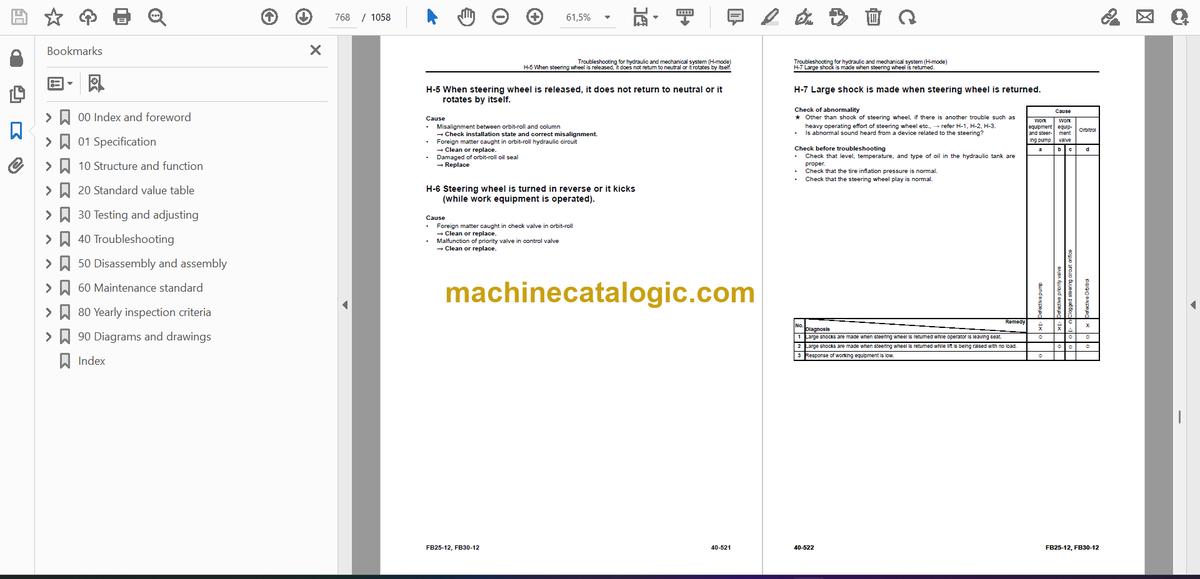
- H-5 When steering wheel is released, it does not return to neutral or it rotates by itself.
- H-6 Steering wheel is turned in reverse or it kicks (while work equipment is operated).
- H-7 Large shock is made when steering wheel is returned.
- H-8 EPACS does not work.
- H-9 Steering wheel vibrates.
- H-10 Steering system makes abnormal sound.
- H-11 Oil leaks from steering circuit.
- H-12 Service brake does not work or its performance is low.
- H-13 Service brake is not released or it drags.
- H-14 Parking brake does not work or its performance is low.
- H-15 Parking brake is not released or drags.
- H-16 Unusual noise is heard from around work equipment and steering pump
- H-17 Lift cylinder and fork are not raised.
- H-18 Lifting speed or power of lift cylinder and fork is insufficient
- H-19 Fork lifting speed lowers at specific height.
- H-20 Hydraulic drift of lift cylinder is large.
- H-21 Lift cylinders do not come down.
- H-22 Fork lowering speed is low or high or fine control performance is low or response is low.
- H-23 Mast does not tilt forward nor backward.
- H-24 Forward/backward tilting speed or force of mast is insufficient.
- H-25 Tilting speed lowers halfway
- H-26 Hydraulic drift of tilt cylinder (forward tilting) is large
- H-27 Mast is unstable during travel with load
- H-28 Steering is heavy when work equipment and steering are operated simultaneously
- 50 Disassembly and assembly
- Contents
- Precautions before work
- General information on disassembly and assembly
- How to read this manual
- Coating materials list
- Special tools list
- Sketches of special tools
- Power train
- Removal and installation of front axle assembly
- Disassembly and assembly of front axle assembly
- Removal and installation of pump motor
- Steering system
- Removal and installation of power steering cylinder assembly
- Disassembly and assembly of power steering cylinder assembly
- Disassembly and assembly of wheel brake assembly
- Removal and installation of Orbitrol valve assembly
- Disassembly and assembly of Orbitrol valve assembly
- Brake system
- Removal and installation of brake master cylinder assembly
- Disassembly and assembly of brake master cylinder assembly
- Removal and installation of parking brake lever
- Undercarriage and frame
- Removal and installation of rear axle assembly
- Disassembly and assembly of rear axle assembly
- Removal and installation of counterweight assembly
- Removal and installation of hood assembly
- Hydraulic system
- Removal and installation of hydraulic tank assembly
- Removal and installation of control valve assembly
- Removal and installation of lift cylinder assembly
- Disassembly and assembly of lift cylinder assembly
- Removal and installation of tilt cylinder assembly
- Disassembly and assembly of tilt cylinder assembly
- Disassembly and assembly of hydraulic pump assembly
- Cab and its attachments
- Removal and installation of operator's seat assembly
- Removal and installation of seat belt assembly
- Removal and installation of seat belt assembly (European specification (including Turkey)) (Serial No.: 104895 and up)
- Removal and installation of head guard assembly
- Removal and installation of directional and work equipment control EPC lever assembly
- Work equipment
- Removal and installation of mast assembly
- Disassembly and assembly of mast assembly
- Removal and installation of chain (double mast)
- Removal and installation of chain (triple mast)
- Electrical system
- Removal and installation of battery assembly
- Removal and installation of master controller assembly
- Removal and installation of inverter assembly
- Removal and installation of monitor panel assembly
- Removal and installation of combination switch assembly
- Removal and installation of travel direction sensor
- Removal and installation of travel speed sensor
- 60 Maintenance standard
- Contents
- Power train
- Front axle
- Differential
- Travel motor
- Pump motor
- Steering system
- Brake system
- Brake control
- Wheel brake
- Brake master cylinder
- Undercarriage and frame
- Hydraulic system
- Work equipment
- Tilt cylinder
- Lift cylinder
- Mast
- Board
- 80 Yearly inspection criteria
- Contents
- Precautions before work
- Yearly inspection criteria
- Yearly inspection criteria
- 90 Diagrams and drawings
- Contents
- Hydraulic diagrams and drawings
- Symbols used in hydraulic circuit diagrams
- Hydraulic circuit diagram
- Electrical diagrams and drawings
- Symbols used in electrical circuit diagrams
- Electric circuit diagram (FB25-12) (1/7)
- Electric circuit diagram (FB25-12) (2/7)
- Electric circuit diagram (FB25-12) (3/7)
- Electric circuit diagram (FB25-12) (4/7)
- Electric circuit diagram (FB25-12) (5/7)
- Electric circuit diagram (FB25-12) (6/7)
- Electric circuit diagram (FB25-12) (7/7)
- Electric circuit diagram (FB30-12) (1/7)
- Electric circuit diagram (FB30-12) (2/7)
- Electric circuit diagram (FB30-12) (3/7)
- Electric circuit diagram (FB30-12) (4/7)
- Electric circuit diagram (FB30-12) (5/7)
- Electric circuit diagram (FB30-12) (6/7)
- Electric circuit diagram (FB30-12) (7/7)
- Electric circuit diagram (FB25-12, FB30-12) (1/2)
- Electric circuit diagram (FB25-12, FB30-12) (2/2)
- Index
Komatsu


