These Komatsu GD655-6, GD675-6, GD675-6E0 motor graders are what you see doing road shaping, shoulder work, snow removal, and final trim on big sites. The Shop Manual SEN06997-03 is what dealers and independent shops like mine reach for when a grader is down and needs real repair work, not just fluid changes. People usually buy this manual when they want to diagnose faults properly, tear into major components, and put the machine back to work without guessing.
What this manual helps you do
- Trace hydraulic problems in the blade, steering, and circle systems using step-by-step test and inspection procedures.
- Diagnose electrical issues in lights, controls, and machine monitoring using wiring information and fault-tracing guides.
- Follow disassembly and reassembly sequences for engine, transmission, axles, and final drives so parts go back in the right order.
- Check adjustment procedures for brakes, linkages, and controls to correct poor response, drift, or uneven grading.
- Verify wear limits and inspection points so you know when to repair a component and when you’re wasting money keeping it in service.
Who this is for
This Komatsu GD655-6, GD675-6, GD675-6E0 Motor Grader Shop Manual is aimed at field techs, shop mechanics, and fleet maintenance managers who actually wrench on these machines. If you just operate the grader and want basic daily checks and safety info, you’d be better off with the Operation & Maintenance Manual instead.
FAQ
Q: Is this a PDF I can search and print?
A: Yes, it’s a PDF you can search by keyword and print pages or sections you need in the shop.
Q: Is the coverage deep enough for engine and transmission rebuilds?
A: Yes, this kind of shop manual usually covers full teardown, inspection, and assembly procedures for major components.
Q: How do I know if it fits my exact grader version?
A: You match your machine’s model and serial plate to GD655-6, GD675-6, or GD675-6E0 and the SEN06997-03 reference; if your tag doesn’t show one of those, this isn’t the right book.
Bottom line: if you’re repairing or diagnosing these specific Komatsu graders and want to save money doing work in-house, this is the right manual; if you only need operating instructions, keep looking.
📘 Show Index
Table of Contents:
- 00 Index and Foreword
- Index
- Abbreviation List
- Foreword, Safety, Basic Information
- How to Read the Shop Manual
- Safety Notice for Operation
- Precautions to Prevent Fire
- Procedures If Fire Occurs
- Precautions for Disposing of Waste Materials
- Engine Technology to Conform Exhaust Gas Emission
- Precautions for DEF
- General Character and Precautions for Handling
- Precautions for Adding
- Precautions for Storage
- Precautions for Fire Hazard and Leakage
- Other Precautions
- Store DEF
- Precautions When You Handle Hydraulic Equipment
- Precautions When You Disconnect and Connect Pipings
- Precautions When You Handle Electrical Equipment
- Precautions When You Handle Fuel System Equipment
- Precautions When You Handle Intake System Equipment
- Practical Use of KOMTRAX
- Disconnect and Connect Push-Pull Type Coupler
- How to Disconnect and Connect Type 1 Push-Pull Type Coupler
- How to Disconnect and Connect Type 2 Push-Pull Type Coupler
- How to Disconnect and Connect Type 3 Push-Pull Type Coupler
- Precautions for Disconnection and Connection of Connectors
- How to Disconnect and Connect Deutsch Connector
- How to Disconnect and Connect Slide Lock Type Connector
- How to Disconnect and Connect Connector with Lock to Pull
- How to Disconnect and Connect Connector with Lock to Push
- How to Disconnect and Connect Connector with Housing to Rotate
- How to Read the Codes for Electric Cable
- Explanation of Terms for Maintenance Standard
- Standard Tightening Torque Table
- Conversion Table
- 01 Specifications
- Table of Contents
- Abbreviation List
- Specifications
- Specification Drawing
- Specification Drawing: GD655-6
- Specification Drawing: GD675-6
- Specification Drawing: GD675-6E0
- Specifications
- Specifications: GD655-6
- Specifications: GD675-6
- Specifications: GD675-6E0
- Weight Table
- Weight Table: GD655-6
- Weight Table: GD675-6
- Weight Table: GD675-6E0
- Table of Fuel, Coolant, and Lubricants
- 10 Structure and Function
- Table of Contents
- Abbreviation List
- Urea SCR System
- Layout Drawing of Urea SCR System
- Urea SCR System Diagram
- Function of Urea SCR System
- Function of DEF System (Machine Without DEF purge relay) (Applicable Machine: 60001 to 61072)
- Function of DEF System (Machine Without DEF purge relay) (Applicable Machine: 61073 and up)
- Function of DEF System (Machine with DEF purge relay) (Applicable Machine: 60001 to 61072)
- Function of DEF System (Machine with DEF purge relay) (Applicable Machine: 61073 and up)
- Inducement Strategy
- Component Parts of Urea SCR System
- DEF Mixing Tube
- SCR Assembly
- DEF Tank
- DEF Pump
- DEF Injector
- DEF Hose
- DEF Tank Heating Valve
- Boot-up System
- Layout Drawing of Boot-up System
- System Operating Lamp System
- System Diagram of System Operating Lamp System (Machine with KOMTRAX Terminal)
- System Diagram of System Operating Lamp System (Machine with Gateway Function Controller)
- Function of System Operating Lamp System (Machine with KOMTRAX Terminal)
- Function of System Operating Lamp System (Machine with Gateway Function Controller) (Machine Without DEF purge relay)
- Function of System Operating Lamp System (Machine with Gateway Function Controller) (Machine with DEF purge relay)
- Battery Disconnect Switch
- Layout Drawing of Battery Disconnect Switch
- Function of Battery Disconnect Switch (Machine with KOMTRAX Terminal)
- Function of Battery Disconnect Switch (Machine with Gateway Function Controller) (Machine Without DEF purge relay)
- Function of Battery Disconnect Switch (Machine with Gateway Function Controller) (Machine with DEF purge relay)
- Preheating System
- System Diagram of Preheating System
- Function of Automatic Preheating System
- Operation of Automatic Preheating System
- Engine System
- Layout Drawing of Engine System
- Function of Engine System
- Engine Control System
- System Diagram of Engine Control
- Function of Engine Control System
- Operation of Engine Control System
- Engine Power Mode Selector System
- Engine Power Mode Selector System Diagram
- Function of Engine Power Mode Selector System
- Operation of Engine Power Mode Selector System
- Automatic Idle Stop System
- Function of Automatic Idle Stop System
- Component Parts of Engine System
- VGT
- EGR System
- EGR Valve
- EGR Cooler
- KCCV System
- KCCV Ventilator
- KDPF
- Cooling System
- Layout Drawing of Cooling System
- Specifications of Cooling System
- Cooling Fan Control System
- System Diagram of Cooling Fan Control System
- Function of Cooling Fan Control System
- Component Parts of Cooling System
- Brake and Cooling Fan Pump
- Cooling Fan Motor
- Control System
- Layout Drawing of Control System
- Machine Monitor System
- System Diagram of Machine Monitor System
- Function of Machine Monitor System
- Rearview Monitor System
- System Diagram of Rearview Monitor System
- Function of Rearview Monitor System
- KOMTRAX System
- KOMTRAX System Diagram (Machine with KOMTRAX Terminal)
- System Diagram of KOMTRAX System (Machine with Gateway Function Controller)
- Function of KOMTRAX System
- Component Parts of Control System
- Machine Monitor
- Switch Panel
- Rearview Monitor
- Rearview Camera
- KOMTRAX Terminal
- Gateway Function Controller
- Communication Terminal
- Transmission Controller
- Monitor Controller
- CAN Terminating Resistor
- Engine Controller
- Accelerator Pedal
- Inching Pedal Potentiometer
- Hydraulic System
- Layout Drawing of Hydraulic System
- Hydraulic System Diagram
- Function of Hydraulic System
- CLSS
- Structure of CLSS
- Function of CLSS
- Component Parts of Hydraulic System
- Hydraulic Tank
- Steering and Work Equipment Pump
- Power Train Pump and Differential Lock Pump
- Control Valve
- Power Train System
- Layout Drawing of Power Train System
- Operation of Power Train System
- Automatic Shift Control System
- Automatic Shift Control System Diagram
- Function of Automatic Shift Control System
- Transmission Control System
- Transmission Control System Diagram
- Shift Lever Positions and Automatic Gear Shift Range
- Transmission Gear Shift Control System
- Variable Horsepower Control (VHPC) Function
- Transmission Protection Function
- Engine Overrun Prevention Function
- Very Low Speed Travel Control Function
- Component Parts of Power Train System
- Drive Shaft
- Torque Converter
- Lockup Clutch ECMV
- Transmission
- Transmission Control Valve
- F, R, 1st, 2nd, 3rd, 4th Clutch ECMV
- Main Relief Valve and Torque Converter Relief Valve
- Axle
- Differential
- Final Drive
- Tandem Drive
- Differential Lock Solenoid Valve
- Work Equipment System
- Layout Drawing of Work Equipment System
- Function of Work Equipment System
- Component Parts of Work Equipment System
- Blade Lift Circuit Accumulator Solenoid Valve
- Blade Lift Circuit Accumulator
- Scarifier Circuit Relief Valve
- Swivel Joint
- Circle Rotation Motor
- Circle Rotation Gear
- Steering System
- Layout Drawing of Steering System
- Function of Steering System
- Component Parts of Steering System
- Priority Valve
- Orbitrol Valve
- LS Pressure Reducing Valve
- Brake System
- Layout Drawing of Brake System
- Component Parts of Brake System
- Brake Circuit Accumulator
- Brake Valve
- Slack Adjuster
- Brake
- Parking Brake Solenoid Valve and Lifter Lock Pin Control Valve
- Parking Brake
- Undercarriage and Frame
- Frame and Center Hinge Pin
- Structure of Frame and Center Hinge Pin
- Function of Frame and Center Hinge Pin
- Tires
- Features of Radial Tire When Compared with Bias Tire
- Structure of Radial Tire
- Function of Radial Tire
- Structure of Bias Tire
- Function of Bias Tire
- Work Equipment
- Structure of Circle and Drawbar
- Function of Circle and Drawbar
- Structure of Blade
- Function of Blade
- Structure of Lifter
- Function of Lifter
- CAB Related Parts
- ROPS CAB
- Structure of ROPS CAB
- Function of ROPS CAB
- 20 Standard Value Table
- Table of Contents
- Abbreviation List
- Standard Value Table for Engine
- Standard Value Table for Engine: GD655-6
- Standard Value Table for Engine: GD675-6
- Standard Value Table for Engine: GD675-6E0
- Standard Value Table for Machine
- Standard Value Table for Machine: GD655-6
- Standard Value Table for Machine: GD675-6
- Standard Value Table for Machine: GD675-6E0
- Machine Posture and Procedures to Measure Performance
- Standard Value Table for Electricity
- Standard Value Table for Electricity
- 30 Testing and Adjusting
- Table of Contents
- Precautions Before Work
- Abbreviation List
- Related Information on Testing and Adjusting
- Tools for Testing and Adjusting
- Sketch of Tools for Testing and Adjusting
- Engine and Cooling System
- Examine Engine Speed
- How to Examine Engine Speed
- Examine Boost Pressure
- How to Examine Boost Pressure
- Examine Exhaust Gas Temperature
- How to Examine Exhaust Gas Temperature
- Examine Exhaust Gas Color
- How to Examine Exhaust Gas Color with the Handy Smoke Checker
- How to Examine Exhaust Gas Color with Smoke Meter
- Examine Mass Air Flow and Temperature Sensor
- How to Examine Mass Air Flow and Temperature Sensor
- Examine and Adjust Valve Clearance
- How to Examine Valve Clearance
- How to Adjust Valve Clearance
- Examine Compression Pressure
- How to Examine Compression Pressure
- Examine Blowby Pressure
- How to Examine Blowby Pressure
- Examine Engine Oil Pressure
- How to Examine Engine Oil Pressure
- Examine EGR Valve and VGT Oil Pressure
- How to Examine EGR Valve and VGT Oil Pressure
- Examine Fuel Pressure
- How to Examine Fuel Pressure
- Examine Fuel Discharge, Return and Leakage
- How to Examine Fuel Discharge, Return, and Leakage
- Bleed Air from Fuel System
- How to Bleed Air from Fuel System
- Examine Fuel Circuit for Leakage
- How to Examine Fuel System for Leakage
- Handle Cylinder Cut-out Mode Operation
- Handle No-Injection Cranking Operation
- Examine KDPF, SCR and Muffler Stack for Looseness and Damage
- How to Examine KDPF, SCR and Muffler Stack for Looseness and Damage
- Examine Installed Condition of Cylinder Heads and Manifolds
- How to Examine Installed Condition of Cylinder Heads and Manifolds
- Examine Engine Piping for Damage and Looseness
- How to Examine Engine Piping for Damage and Looseness
- Examine and Adjust Air Conditioner Compressor Belt Tension
- How to Examine Air Conditioner Compressor Belt Tension
- How to Adjust Air Conditioner Compressor Belt Tension
- Examine Alternator Belt
- How to Examine Alternator Belt
- Examine Automatic Tensioner
- How to Examine Automatic Tensioner
- Correct Soot Accumulation Correction Value by Ash Influence
- How to Correct Soot Accumulation Correction Value by Ash Influence
- Examine SCR Related Functions
- Examine DEF Pump Raised Pressure
- Examine Injection Volume from DEF Injector
- Examine DEF Line Heater Relay 1
- Examine DEF Line Heater Relay 2
- Examine DEF Pump Heater Relay
- Examine DEF Tank Heater Valve
- Examine SCR Denitration Efficiency
- Clean DEF Tank
- Clean DEF Pump
- Power Train
- Examine Power Train Oil Pressure
- How to Examine Power Train Oil Pressure
- Adjust Transmission Input Shaft Speed Sensor
- How to Adjust Transmission Input Shaft Speed Sensor
- Adjust Transmission Intermediate Shaft Speed Sensor
- How to Adjust Transmission Intermediate Shaft Speed Sensor
- Adjust Transmission Output Shaft Speed Sensor
- How to Adjust Transmission Output Shaft Speed Sensor
- Examine After You Adjust Transmission Speed Sensor
- How to Examine After Adjustment of Transmission Speed Sensor
- Flush Torque Converter and Transmission Hydraulic Circuit
- How to Flush Torque Converter and Transmission Hydraulic Circuit
- Move Disabled Machine Due to Transmission Valve Failure
- How to Move Disabled Machine Due to Transmission Valve Failure
- Examine Drive Shaft for Looseness, Backlash, and Damage
- How to Examine Drive Shaft for Looseness, Backlash, and Damage
- Examine and Adjust Differential Lock Hydraulic Oil Pressure
- How to Examine Differential Lock Oil Pressure
- How to Adjust Differential Lock Oil Pressure
- Steering System
- Examine and Adjust Steering Circuit Oil Pressure
- How to Examine Steering Circuit Oil Pressure
- How to Adjust Steering Circuit Oil Pressure
- Examine Internal Oil Leakage of Steering Cylinder
- How to Examine Oil Leakage from Steering Cylinder
- Bleed Air from Steering Circuit
- How to Bleed Air from Steering Circuit
- Examine and Adjust Toe-in
- How to Examine Toe-in
- How to Adjust Toe-in
- Adjust Bearing Preload
- How to Adjust Bearing Preload
- Brake System
- Release Remained Pressure from Brake Circuit
- How to Release Remained Pressure from Brake Circuit
- Examine Wheel Brake Oil Pressure
- How to Examine Wheel Brake Oil Pressure
- Examine and Adjust Accumulator Charge Pressure
- How to Examine Accumulator Charge Pressure
- How to Adjust Accumulator Charge Pressure
- Examine Nitrogen Gas Pressure in Brake Accumulator and Charge Gas
- How to Examine Accumulator Nitrogen Gas Pressure for Brake
- How to Charge Brake Accumulator Nitrogen Gas
- Bleed Air from Brake Circuit
- How to Bleed Air from Brake Circuit
- Examine Pressure Decrease of Wheel Brake
- How to Examine Pressure Decrease of Wheel Brake
- Examine Wear of Wheel Brake Disc
- How to Examine Wear of Wheel Brake Disc
- Examine Parking Brake Oil Pressure
- How to Examine Parking Brake Oil Pressure
- Release Parking Brake Manually
- How to Release Parking Brake Manually
- Examine and Adjust Parking Brake Pad
- How to Examine Wear of Parking Brake Pad
- How to Adjust Clearance of Parking Brake Pad
- Hydraulic System
- Examine and Adjust Work Equipment Oil Pressure
- How to Examine Work Equipment Oil Pressure
- How to Adjust Work Equipment Oil Pressure
- Examine and adjust oil pressure in pump PC control circuit
- How to Examine PC Valve Outlet Pressure (Servo Piston Inlet Pressure)
- How to Adjust Oil Pressure in Pump PC Control Circuit
- Examine and Adjust Oil Pressure in Pump LS Control Circuit
- How to Examine LS Differential Pressure
- How to Adjust LS Valve
- Examine Oil Pressure of Lifter Lock Pin Circuit
- How to Examine Oil Pressure of Lifter Lock Pin Circuit
- Bleed Air from Work Equipment Circuit
- How to Bleed Air from Work Equipment Circuit
- Examine Cooling Fan Speed
- How to Examine Cooling Fan Speed
- Examine Cooling Fan Circuit Oil Pressure
- How to Examine Cooling Fan Circuit Oil Pressure
- Examine Oil Leakage from Work Equipment Cylinder
- How to Examine Oil Leakage from Blade Lift Cylinder
- How to Examine Oil Leakage from Blade Side-Shift Cylinder
- How to Examine Oil Leakage from Drawbar Side-Shift Cylinder
- How to Examine Oil Leakage from Power Tilt Cylinder
- How to Examine Oil Leakage from Articulate Cylinder
- How to Examine Oil Leakage from Leaning Cylinder
- Work Equipment
- Adjust Clearance in Drawbar Joint
- How to Adjust Clearance in Drawbar Joint
- Examine and Adjust Clearance in Circle Guide
- How to Examine Clearance in Circle Guide
- How to Adjust Clearance in Circle Guide
- Examine and Adjust Circle Rotation Gear
- How to Examine Circle Rotation Gear
- How to Adjust Circle Rotation Gear
- Charge Blade Accumulator Nitrogen Gas Pressure
- How to Charge Blade Accumulator Nitrogen Gas
- Electrical System
- Set and Adjust Each Equipment
- Set and Operate Machine Monitor
- Operator Mode
- Function to Show Technician Identification Status Screen
- Function to Show Operator Identification Input Screen
- Examine Function by LCD (Liquid Crystal Display)
- Examine Function of Service Meter and Odometer
- How to Set Usage Limitation and Change Maintenance Password
- Service Mode
- How to Operate Service Mode
- How to See Pre-defined Monitoring Information
- How to Examine Self-Define Monitor Information
- Abnormality Record Menu
- How to See Maintenance Record
- Maintenance Mode Setting
- How to Set Phone Number Entry
- Default Menu
- Diagnostic Tests Menu
- Adjustment Menu
- No-Injection Cranking Operation
- KOMTRAX Settings Menu
- How to Show Service Message
- How to Start Up KOMTRAX Terminal (Machine with KOMTRAX Terminal)
- How to Stop Use of KOMTRAX Terminal (Machine with KOMTRAX Terminal)
- How to Start Up KOMTRAX System (Machine with Gateway Function Controller)
- How to Stop Use of KOMTRAX System (Machine with Gateway Function Controller)
- Adjust Rearview Camera Angle
- How to Adjust Rearview Camera Angle
- Set Region of Bluetooth(R) Compatible Radio
- How to Set Region of Bluetooth(R) Compatible Radio
- Handle Voltage Circuit of Engine Controller
- Handle Battery Disconnect Switch (Machine with KOMTRAX Terminal)
- Handle Battery Disconnect Switch (Machine with Gateway Function Controller)
- Examine Diodes
- How to Examine Diodes by Digital Tester
- How to Examine Diodes by Analog Tester
- Pm Clinic
- Pm Clinic Service
- Pm Clinic Check Sheet: GD655-6
- Pm Clinic Check Sheet: GD675-6
- Pm Clinic Check Sheet: GD675-6E0
- 40 Troubleshooting
- Table of Contents
- Precautions Before Work
- Abbreviation List
- Related Information to Troubleshooting
- General Troubleshooting Points
- Troubleshooting Points for Urea SCR System
- Sequence of Events in Troubleshooting
- Checks Before Troubleshooting
- Inspection Procedure Before Troubleshooting
- Test in Accordance with Testing Procedure
- Examine Fuel Level and Type
- Examine for Impure Ingredient in Fuel
- Examine DEF Level and Type
- Examine Fuel Prefilter
- Examine Fuel Main Filter
- Examine Water Pump for Leakage
- Examine Engine Oil Level (Oil Quantity in Oil Pan) and Type
- Examine Coolant Level (Reservoir Tank)
- Examine Air Cleaner Clogging
- Clean Outer Element
- Replace Element
- Examine Hydraulic Oil Level
- Examine Hydraulic Oil Strainer
- Examine Hydraulic Oil Filter
- Examine Oil Level in Transmission Case
- Examine Transmission Case Strainer
- Replace Transmission Oil Filter Cartridge
- Examine Oil Level in Final Drive Case
- Bleed Air from Fuel System
- Bleed Air from Hydraulic System
- How to Examine Electric Equipment
- Preparation for Troubleshooting of Electrical System
- Procedure for Troubleshooting
- Symptom and Troubleshooting Numbers
- Information Shown in Troubleshooting Table
- How to Diagnose Wiring Harness for Open Circuit of Pressure Sensor System
- Connector List and Layout (Machine with KOMTRAX Terminal)
- Connector List and Layout (Machine with Gateway Function Controller)
- Connector Contact Connection Table
- T-Branch Box and T-Branch Adapter Table
- Fuse Location Table (Machine with KOMTRAX Terminal)
- Fuse Location Table (Machine with Gateway Function Controller)
- Precautions When You Clean and Replace KDPF (KCSF and KDOC)
- Prepare Troubleshoot Machine Monitor
- Procedure to Make Harness Checker on Machine Monitor LCD Unit
- Prepare Short Circuit Electrical Connector (For Failure Codes [CA1883] and [CA3135])
- Failure Code Table
- Troubleshooting by Failure Code (Display of Code)
- Failure Code [1500L0]
- Failure Code [15G0MW]
- Failure Code [15H0MW]
- Failure Code [15J0MW]
- Failure Code [15K0MW]
- Failure Code [15L0MW]
- Failure Code [15M0MW]
- Failure Code [15N0MW]
- Failure Code [15SBL1]
- Failure Code [15SBMA]
- Failure Code [15SCL1]
- Failure Code [15SCMA]
- Failure Code [15SDL1]
- Failure Code [15SDMA]
- Failure Code [15SEL1]
- Failure Code [15SEMA]
- Failure Code [15SFL1]
- Failure Code [15SFMA]
- Failure Code [15SGL1]
- Failure Code [15SGMA]
- Failure Code [15SHL1]
- Failure Code [15SHMA]
- Failure Code [15SJMA]
- Failure Code [15U0NT]
- Failure Code [2F00MA]
- Failure Code [2F00MB]
- Failure Code [2G42ZG]
- Failure Code [2G43ZG]
- Failure Code [989L00]
- Failure Code [989M00]
- Failure Code [989N00]
- Failure Code [A1U0N3]
- Failure Code [A1U0N4]
- Failure Code [AA10NX]
- Failure Code [AB00KE]
- Failure Code [AB00KY]
- Failure Code [AQ10N3]
- Failure Code [AS00N3]
- Failure Code [AS00R2]
- Failure Code [AS00R3]
- Failure Code [AS00R4]
- Failure Code [AS00R5]
- Failure Code [AS00R6]
- Failure Code [AS00ZK]
- Failure Code [AS10KM]
- Failure Code [AS10NR]
- Failure Code [AS10NT]
- Failure Code [B@BAZG]
- Failure Code [B@BCNS]
- Failure Code [B@BCQA]
- Failure Code [B@BCZK]
- Failure Code [B@CENS]
- Failure Code [B@CKNS]
- Failure Code [B@HANS]
- Failure Code [CA115]
- Failure Code [CA122]
- Failure Code [CA123]
- Failure Code [CA131]
- Failure Code [CA132]
- Failure Code [CA144]
- Failure Code [CA145]
- Failure Code [CA153]
- Failure Code [CA154]
- Failure Code [CA187]
- Failure Code [CA221]
- Failure Code [CA222]
- Failure Code [CA227]
- Failure Code [CA234]
- Failure Code [CA238]
- Failure Code [CA239]
- Failure Code [CA249]
- Failure Code [CA256]
- Failure Code [CA271]
- Failure Code [CA272]
- Failure Code [CA322]
- Failure Code [CA323]
- Failure Code [CA324]
- Failure Code [CA325]
- Failure Code [CA331]
- Failure Code [CA332]
- Failure Code [CA343]
- Failure Code [CA351]
- Failure Code [CA352]
- Failure Code [CA356]
- Failure Code [CA357]
- Failure Code [CA386]
- Failure Code [CA428]
- Failure Code [CA429]
- Failure Code [CA431]
- Failure Code [CA432]
- Failure Code [CA435]
- Failure Code [CA441]
- Failure Code [CA442]
- Failure Code [CA449]
- Failure Code [CA451]
- Failure Code [CA452]
- Failure Code [CA488]
- Failure Code [CA515]
- Failure Code [CA516]
- Failure Code [CA553]
- Failure Code [CA555]
- Failure Code [CA556]
- Failure Code [CA559]
- Failure Code [CA595]
- Failure Code [CA687]
- Failure Code [CA689]
- Failure Code [CA691]
- Failure Code [CA692]
- Failure Code [CA697]
- Failure Code [CA698]
- Failure Code [CA731]
- Failure Code [CA778]
- Failure Code [CA1117]
- Failure Code [CA1664]
- Failure Code [CA1669]
- Failure Code [CA1673]
- Failure Code [CA1677]
- Failure Code [CA1678]
- Failure Code [CA1682]
- Failure Code [CA1683]
- Failure Code [CA1684]
- Failure Code [CA1686]
- Failure Code [CA1691]
- Failure Code [CA1694]
- Failure Code [CA1695]
- Failure Code [CA1696]
- Failure Code [CA1712]
- Failure Code [CA1713]
- Failure Code [CA1714]
- Failure Code [CA1715]
- Failure Code [CA1776]
- Failure Code [CA1777]
- Failure Code [CA1843]
- Failure Code [CA1844]
- Failure Code [CA1879]
- Failure Code [CA1881]
- Failure Code [CA1883] (GD655-6, GD675-6)
- Failure Code [CA1883] (GD675-6E0)
- Failure Code [CA1885]
- Failure Code [CA1887]
- Failure Code [CA1921]
- Failure Code [CA1922]
- Failure Code [CA1942]
- Failure Code [CA1993] (GD655-6, GD675-6)
- Failure Code [CA1993] (GD675-6E0)
- Failure Code [CA2185]
- Failure Code [CA2186]
- Failure Code [CA2249]
- Failure Code [CA2271]
- Failure Code [CA2272]
- Failure Code [CA2288]
- Failure Code [CA2311]
- Failure Code [CA2349]
- Failure Code [CA2353]
- Failure Code [CA2357]
- Failure Code [CA2381]
- Failure Code [CA2382]
- Failure Code [CA2383]
- Failure Code [CA2386]
- Failure Code [CA2387]
- Troubleshooting Flowchart
- Failure Code [CA2555]
- Failure Code [CA2556]
- Failure Code [CA2637]
- Failure Code [CA2639]
- Failure Code [CA2771]
- Failure Code [CA2777]
- Failure Code [CA2976]
- Failure Code [CA3133]
- Failure Code [CA3134]
- Failure Code [CA3135]
- Failure Code [CA3142]
- Failure Code [CA3143]
- Failure Code [CA3144]
- Failure Code [CA3146]
- Failure Code [CA3147]
- Failure Code [CA3148]
- Failure Code [CA3151]
- Failure Code [CA3165]
- Failure Code [CA3229]
- Failure Code [CA3231]
- Failure Code [CA3232]
- Failure Code [CA3235]
- Failure Code [CA3239]
- Failure Code [CA3241]
- Failure Code [CA3242]
- Failure Code [CA3251]
- Failure Code [CA3253]
- Failure Code [CA3254]
- Failure Code [CA3255]
- Failure Code [CA3256]
- Failure Code [CA3311]
- Failure Code [CA3312]
- Failure Code [CA3313]
- Failure Code [CA3314]
- Failure Code [CA3315]
- Failure Code [CA3316]
- Failure Code [CA3317]
- Failure Code [CA3318]
- Failure Code [CA3319]
- Failure Code [CA3321]
- Failure Code [CA3322]
- Failure Code [CA3419]
- Failure Code [CA3421]
- Failure Code [CA3497]
- Failure Code [CA3498]
- Failure Code [CA3543]
- Failure Code [CA3545]
- Failure Code [CA3547]
- Failure Code [CA3558]
- Failure Code [CA3559]
- Failure Code [CA3562]
- Failure Code [CA3563]
- Failure Code [CA3567]
- Failure Code [CA3568]
- Failure Code [CA3571]
- Failure Code [CA3572]
- Failure Code [CA3574]
- Failure Code [CA3575]
- Failure Code [CA3577]
- Failure Code [CA3578]
- Failure Code [CA3582]
- Failure Code [CA3583]
- Failure Code [CA3596]
- Failure Code [CA3649]
- Failure Code [CA3681]
- Failure Code [CA3682]
- Failure Code [CA3713]
- Failure Code [CA3717]
- Failure Code [CA3718]
- Failure Code [CA3725]
- Failure Code [CA3741]
- Failure Code [CA3748]
- Failure Code [CA3751]
- Failure Code [CA3755]
- Failure Code [CA3866]
- Failure Code [CA3867]
- Failure Code [CA3868]
- Failure Code [CA3899]
- Failure Code [CA3911]
- Failure Code [CA3912]
- Failure Code [CA3932]
- Failure Code [CA3933]
- Failure Code [CA3934]
- Failure Code [CA3935]
- Failure Code [CA3936]
- Failure Code [CA4151]
- Failure Code [CA4152]
- Failure Code [CA4155]
- Failure Code [CA4156]
- Failure Code [CA4157]
- Failure Code [CA4158]
- Failure Code [CA4159]
- Failure Code [CA4161]
- Failure Code [CA4162]
- Failure Code [CA4163]
- Failure Code [CA4164]
- Failure Code [CA4165]
- Failure Code [CA4166]
- Failure Code [CA4168]
- Failure Code [CA4169]
- Failure Code [CA4171]
- Failure Code [CA4249]
- Failure Code [CA4251]
- Failure Code [CA4259]
- Failure Code [CA4261]
- Failure Code [CA4277]
- Failure Code [CA4281]
- Failure Code [CA4459]
- Failure Code [CA4461]
- Failure Code [CA4658]
- Failure Code [CA4731]
- Failure Code [CA4732]
- Failure Code [CA4739]
- Failure Code [CA4768]
- Failure Code [CA4769]
- Failure Code [CA4842]
- Failure Code [CA4952] (Machine with KOMTRAX Terminal)
- Failure Code [CA4952] (Machine with Gateway Function Controller) (Applicable Machine: 60001 to 60873)
- Failure Code [CA4952] (Machine with Gateway Function Controller) (Applicable Machine: 60874 and Up)
- Failure Code [CA5115]
- Failure Code [CA5179]
- Failure Code [CA5181]
- Failure Code [CA5383]
- Failure Code [D160KA]
- Failure Code [D160KB]
- Failure Code [D160KY]
- Failure Code [D19JKZ]
- Failure Code [D19KKZ]
- Failure Code [D1EHKA]
- Failure Code [D1EHKB]
- Failure Code [D1EHKY]
- Failure Code [D1FBKB]
- Failure Code [D5ZHL6]
- Failure Code [D811MC]
- Failure Code [D862KA]
- Failure Code [D8ALKA] (Machine with KOMTRAX Terminal)
- Failure Code [D8ALKA] (Machine with Gateway Function Controller) (Applicable Machine: 60001 to 60873)
- Failure Code [D8ALKA] (Machine with Gateway Function Controller) (Applicable Machine: 60874 and Up)
- Failure Code [D8ALKB] (Machine with KOMTRAX Terminal)
- Failure Code [D8ALKB] (Machine with Gateway Function Controller) (Applicable Machine: 60001 to 60873)
- Failure Code [D8ALKB] (Machine with Gateway Function Controller) (Applicable Machine: 60874 and Up)
- Failure Code [D8AQK4]
- Failure Code [D8AQKR]
- Failure Code [D8G1KT]
- Failure Code [D8G6KT]
- Failure Code [DAF0KT]
- Failure Code [DAF0MB]
- Failure Code [DAF0MC]
- Failure Code [DAF3KK]
- Failure Code [DAF8KB]
- Failure Code [DAFDKB]
- Failure Code [DAFGMC]
- Failure Code [DAFLKA] (Machine with KOMTRAX Terminal)
- Failure Code [DAFLKA] (Machine with Gateway Function Controller) (Applicable Machine: 60001 to 60873)
- Failure Code [DAFLKA] (Machine with Gateway Function Controller) (Applicable Machine: 60874 and Up)
- Failure Code [DAFLKB] (Machine with KOMTRAX Terminal)
- Failure Code [DAFLKB] (Machine with Gateway Function Controller) (Applicable Machine: 60001 to 60873)
- Failure Code [DAFLKB] (Machine with Gateway Function Controller) (Applicable Machine: 60874 and Up)
- Failure Code [DAFQKR]
- Failure Code [DAQ0KK]
- Failure Code [DAQ0KT]
- Failure Code [DAQ0MC]
- Failure Code [DAQ1KA]
- Failure Code [DAQ2KK]
- Failure Code [DAQ9KQ]
- Failure Code [DAQLKA] (Machine with KOMTRAX Terminal)
- Failure Code [DAQLKA] (Machine with Gateway Function Controller) (Applicable Machine: 60001 to 60873)
- Failure Code [DAQLKA] (Machine with Gateway Function Controller) (Applicable Machine: 60874 and Up)
- Failure Code [DAQLKB] (Machine with KOMTRAX Terminal)
- Failure Code [DAQLKB] (Machine with Gateway Function Controller) (Applicable Machine: 60001 to 60873)
- Failure Code [DAQLKB] (Machine with Gateway Function Controller) (Applicable Machine: 60874 and Up)
- Failure Code [DAQQKR]
- Failure Code [DAQRKR]
- Failure Code [DAQRMA]
- Failure Code [DB2QKR] (Machine with KOMTRAX Terminal)
- Failure Code [DB2QKR] (Machine with Gateway Function Controller)
- Failure Code [DB2RKR] (Machine with KOMTRAX Terminal)
- Failure Code [DB2RKR] (Machine with Gateway Function Controller)
- Failure Code [DD1PKB]
- Failure Code [DD1QKB]
- Failure Code [DDAAL6]
- Failure Code [DDB6L4]
- Failure Code [DDTHKA]
- Failure Code [DDTJKA]
- Failure Code [DDTKKA]
- Failure Code [DDTLKA]
- Failure Code [DDTMKA]
- Failure Code [DDTNKA]
- Failure Code [DDTPKA]
- Failure Code [DF10KA]
- Failure Code [DF10L4]
- Failure Code [DGF1KX]
- Failure Code [DGH2KB]
- Failure Code [DGT1KX]
- Failure Code [DGT7KB]
- Failure Code [DHA4KA]
- Failure Code [DHAAMA]
- Failure Code [DHACMA]
- Failure Code [DHT8KA]
- Failure Code [DHT8KB]
- Failure Code [DHT8ZG]
- Failure Code [DJF1KA]
- Failure Code [DK70KX]
- Failure Code [DKD0KX]
- Failure Code [DLF1KA]
- Failure Code [DLF1LC]
- Failure Code [DLF2KA]
- Failure Code [DLF2LC]
- Failure Code [DLM3KA]
- Failure Code [DLM3LC]
- Failure Code [DLM3MB]
- Failure Code [DLT3KA]
- Failure Code [DPQ1KR]
- Failure Code [DPQ2KR]
- Failure Code [DPQ3KR]
- Failure Code [DV00KB]
- Failure Code [DW4BKA]
- Failure Code [DW4BKB]
- Failure Code [DW4BKY]
- Failure Code [DW7BKA]
- Failure Code [DW7BKB]
- Failure Code [DW7BKY]
- Failure Code [DX16KA]
- Failure Code [DX16KB]
- Failure Code [DX16KY]
- Failure Code [DXH1KA]
- Failure Code [DXH1KB]
- Failure Code [DXH1KY]
- Failure Code [DXH2KA]
- Failure Code [DXH2KB]
- Failure Code [DXH2KY]
- Failure Code [DXH3KA]
- Failure Code [DXH3KB]
- Failure Code [DXH3KY]
- Failure Code [DXH4KA]
- Failure Code [DXH4KB]
- Failure Code [DXH4KY]
- Failure Code [DXH5KA]
- Failure Code [DXH5KB]
- Failure Code [DXH5KY]
- Failure Code [DXH6KA]
- Failure Code [DXH6KB]
- Failure Code [DXH6KY]
- Failure Code [DXH7KA]
- Failure Code [DXH7KB]
- Failure Code [DXH7KY]
- Failure Code [DXHHKA]
- Failure Code [DXHHKB]
- Failure Code [DXHHKY]
- Failure Code [F313KA]
- Failure Code [F313KB]
- Failure Code [F314KA]
- Failure Code [F314KB]
- Failure Code [F315KB]
- Failure Code [F315KY]
- Failure Code [F316KB]
- Failure Code [F316KY]
- Failure Code [F318KB]
- Failure Code [F318KY]
- Failure Code [F31AKB]
- Failure Code [F31AKY]
- Failure Code [F31BKB]
- Failure Code [F31BKY]
- Failure Code [F31CKB]
- Failure Code [F31CKY]
- Failure Code [F31DKB]
- Failure Code [F31DKY]
- Failure Code [F31EKB]
- Failure Code [F31EKY]
- Failure Code [FS10ZE]
- Troubleshooting of Electrical System (E-Mode)
- Engine Does Not Start (Engine Does Not Crank)
- Manual Preheating System Does Not Operate
- Automatic Preheating System Does Not Operate
- While Preheating is in Operation, Preheating Pilot Lamp Does Not Come On
- Engine Coolant Temperature Gauge Does Not Show Correct Temperature
- LCD Unit and LED Unit on Machine Monitor Do Not Show Anything
- LCD Unit on Machine Monitor Shows Nothing
- Backlight of LCD Unit on Machine Monitor is Abnormal (Backlight Goes Off or Flickers)
- LCD Screen on Machine Monitor Does Not Show Correctly
- LED Unit Lamp on Machine Monitor is Abnormal
- Switch of Switch Panel on Machine Monitor Does Not Operate
- Two Switches Operation of Switch Panel on Machine Monitor Does Not Operate
- Switch Panel Buzzer of Machine Monitor is Abnormal
- Some Items of Gauges and Caution Lamps on Machine Monitor are Not Shown Normally
- DEF Level is Not Shown Correctly
- Rearview Monitor Does Not Come On or Backlight Flickers
- Rearview Monitor Images are Not Shown Clearly
- Rearview Monitor Brightness Cannot be Adjusted
- Night Mode Lamp of Rearview Monitor is Abnormal
- Air Cleaner Clogging Caution Lamp Does Not Come On
- Radiator Coolant Level Caution Lamp Does Not Come On
- Brake Oil Pressure Caution Lamp Does Not Come On When Front Brake Accumulator Oil Pressure is Low
- Brake Oil Pressure Caution Lamp Does Not Come On When Rear Brake Accumulator Oil Pressure is Low
- Speedometer Does Not Show Normally
- Engine Tachometer Does Not Show Normally
- Fuel Gauge Does Not Show Normally
- Torque Converter Oil Temperature Gauge Does Not Show Normally
- Articulation Indicator Does Not Show Actual Articulated Angle
- Hydraulic Oil Temperature Gauge Does Not Rise or Hydraulic Oil Temperature Caution Lamp Does Not Come On
- Seatbelt Caution Lamp Does Not Show Normally
- Alarm Buzzer Does Not Operate
- Alarm Buzzer Does Not Stop
- Engine Mode Selector Function Does Not Operate Correctly
- Transmission Selector Function Does Not Operate Normally
- Differential Lock Function Does Not Operate or Cannot be Cancelled
- Lock by Lifter Lock Pin Cannot be Done or Cannot be Cancelled
- Lifter Lock Pin Pilot Lamp Does Not Show Correctly
- Blade Accumulator Function Does Not Operate or Cannot be Cancelled
- Blade Accumulator Pilot Lamp Does Not Show Correctly
- Horn Does Not Sound
- Horn Does Not Stop
- Backup Alarm Does Not Sound
- Backup Alarm Continues to Sound and Backup Lamp Keeps Lit
- Headlamp, Clearance Lamp, and Tail Lamp Do Not Come On
- Headlamp Does Not Come On or Go Out
- Headlamp Selection (Low or High Beam) Cannot be Done
- Headlamp (High Beam) Does Not Come On
- Front Working Lamp Does Not Come On or Go Out
- Working Lamp Pilot Lamp Does Not Come On or Go Out
- Rear Working Lamp Does Not Come On or Go Out
- Turn Signal Lamp and Hazard Lamp Do Not Come On or Go Off
- Turn Signal Lamp Does Not Come On or Go Out
- Hazard Lamp Does Not Come On or Go Out
- Turn Signal Lamp Does Not Come On or Go Off
- Brake Lamp Does Not Come On or Stays Lit
- Backup Lamp Does Not Come On
- No Wiper Operates
- Front Wiper Does Not Operate
- Rear Wiper Does Not Operate
- Right and Left Door Wipers Do Not Operate
- Left Door Wiper Does Not Operate
- Right Door Wiper Does Not Operate
- Front or Door Washer Does Not Operate
- Rear Washer Does Not Operate
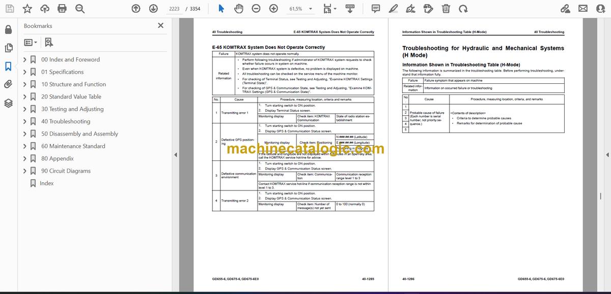
- KOMTRAX System Does Not Operate Correctly
- Troubleshooting for Hydraulic and Mechanical Systems (H Mode)
- Information Shown in Troubleshooting Table (H-Mode)
- Failure Mode and Cause Table
- Machine Does Not Start
- Lockup is Not Released
- Torque Converter Lockup Clutch Does Not Engage
- Machine Does Not Upshift or Downshift from Neutral
- Machine Does Not Upshift or Downshift
- Travel Speed or Power is Low
- Travel Speed or Power is Low in Specified Gear
- Time Lag is Large When You Start Machine or Shift Gears
- Torque Converter Oil Temperature is High
- Differential Lock Function Does Not Operate or Cannot be Cancelled
- Unusual Noise is Heard from Around Hydraulic Pump
- Engine Speed Drops Largely or Engine Stops
- Steering Wheel is Disabled
- Steering Speed or Power is Not Sufficient
- Steering Wheel Does Not Move or is Heavy to Operate
- Wheel Brakes Do Not Operate or are Weak
- Wheel Brakes are Not Released or Drag
- Parking Brake Does Not Operate or is Weak
- Parking Brake is Not Released or Drags
- Lifter Lock Pin is Not Locked or Not Cancelled
- All Work Equipment Operate Slowly
- All Work Equipment Do Not Operate
- Blade Lift Speed or Power is Low
- Drawbar Side-Shift Speed or Power is Low
- Blade Side-Shift Speed or Power is Low
- Power Tilt Speed or Power is Low
- Articulate Speed or Power is Low
- Leaning Speed or Power is Low
- Hydraulic Drift of Blade Lift is Large
- Hydraulic Drift of Leaning is Large
- Blade Does Not Rotate
- Blade Accumulator Function Does Not Operate or Cannot be Cancelled
- Fan Speed is Abnormal (Too High or Low, or Does Not Rotate)
- Unusual Noise is Heard from Around Fan
- Troubleshooting of Engine (S-Mode)
- Information Shown in Troubleshooting Table (S-Mode)
- Engine Does Not Crank When Starting Switch is Turned to Start Position
- Engine Cranks but No Exhaust Smoke Comes Out
- Fuel is Sprayed but Engine Does Not Start (Misfiring: Engine Cranks but Does Not Start)
- Engine Startability is Unsatisfactory
- Engine Does Not Pick Up Smoothly
- Engine Stops During Operation
- Engine Does Not Rotate Smoothly
- Engine Lacks Output (or Lacks Power)
- KDPF Becomes Clogged in a Short Time
- Engine Oil Consumption is Excessive
- Engine Oil Becomes Dirty Quickly
- Fuel Consumption is Excessive
- Oil is in Coolant (or Coolant Spurts Back or Coolant Level Goes Down)
- Engine Oil Pressure Drops
- Fuel Mixes Into Engine Oil
- Water Mixes Into Engine Oil (Milky)
- Coolant Temperature Increases Too High (Overheat)
- Unusual Noise is Heard
- Vibration is Excessive
- Air Cannot be Bled from Fuel Circuit
- Active Regeneration is Done Frequently
- Active Regeneration Continues Long
- White Smoke is Exhausted During Active Regeneration
- DEF Consumption is Excessive
- There is an Unusual Smell (Irritating Odor)
- Foreign Materials Enter DEF (DEF Increases)
- 50 Disassembly and Assembly
- Table of Contents
- Precautions Before Work
- Abbreviation List
- Related Information on Disassembly and Assembly
- How to Read This Manual
- Coating Materials List
- Special Tool List
- Sketches of Special Tools
- Engine and Cooling System
- Remove and Install Supply Pump Assembly
- How to Remove Supply Pump Assembly
- How to Install Supply Pump Assembly
- Remove and Install Injector Assembly
- How to Remove Injector Assembly
- How to Install Injector Assembly
- Remove and Install Cylinder Head Assembly
- How to Remove Cylinder Head Assembly
- How to Install Cylinder Head Assembly
- Remove and Install EGR Valve Assembly
- How to Remove EGR Valve Assembly
- How to Install EGR Valve Assembly
- Remove and Install EGR Cooler Assembly
- How to Remove EGR Cooler Assembly
- How to Install EGR Cooler Assembly
- Remove and Install Starter Assembly
- How to Remove Starting Motor Assembly
- How to Install Starting Motor Assembly
- Remove and Install Alternator Belt
- How to Remove Alternator Belt
- How to Install Alternator Belt
- Remove and Install Automatic Tensioner
- How to Remove Automatic Tensioner
- How to Install Automatic Tensioner
- Remove and Install Radiator Assembly
- How to Remove Radiator Assembly
- How to Install Radiator Assembly
- Remove and Install Aftercooler Assembly
- How to Remove Aftercooler Assembly
- How to Install Aftercooler Assembly
- Remove and Install Power Train Oil Cooler Assembly
- How to Remove Power Train Oil Cooler Assembly
- How to Install Power Train Oil Cooler Assembly
- Remove and Install Cooling Fan Motor Assembly
- How to Remove Cooling Fan Motor Assembly
- How to Install Cooling Fan Motor Assembly
- Remove and Install Engine, Torque Converter, and Transmission Assembly
- How to Remove Engine, Torque Converter, and Transmission Assembly
- How to Install Engine, Torque Converter, and Transmission Assembly
- Disconnect and Connect Engine, Torque Converter, and Transmission Assembly
- How to Disconnect Engine, Torque Converter, and Transmission Assembly
- How to Connect Engine, Torque Converter, and Transmission Assembly
- Remove and Install Engine Front Oil Seal
- How to Remove Engine Front Oil Seal
- How to Install Engine Front Oil Seal
- Remove and Install Engine Rear Oil Seal
- How to Remove Engine Rear Oil Seal
- How to Install Engine Rear Oil Seal
- Remove and Install Engine Hood Assembly
- How to Remove Engine Hood Assembly
- How to Install Engine Hood Assembly
- Remove and Install Fuel Tank Assembly
- How to Remove Fuel Tank Assembly
- How to Install Fuel Tank Assembly
- Remove and Install DEF Tank Assembly
- How to Remove DEF Tank Assembly
- How to Install DEF Tank Assembly
- Remove and Install DEF Tank Sensor Flange Assembly
- How to Remove DEF Tank Sensor Flange Assembly
- How to Install DEF Tank Sensor Flange Assembly
- Remove and Install DEF Tank Sensor
- How to Remove DEF Tank Sensor
- How to Install DEF Tank Sensor
- Remove and Install DEF Tank Strainer
- How to Remove DEF Tank Strainer
- How to Install DEF Tank Strainer
- Remove and Install KDPF Assembly
- How to Remove KDPF Assembly
- How to Install KDPF Assembly
- Disassemble and Assemble KDPF Assembly
- How to Disassemble KDPF Assembly
- How to Assemble KDPF Assembly
- Remove and Install SCR Assembly
- How to Remove SCR Assembly
- How to Install SCR Assembly
- Remove and Install KDPF and SCR Assembly
- How to Remove KDPF and SCR Assembly
- How to Install KDPF and SCR Assembly
- Remove and Install KCCV Assembly
- How to Remove KCCV Assembly
- How to Install KCCV Assembly
- Remove and Install DEF Mixing Tube
- How to Remove DEF Mixing Tube
- How to Install DEF Mixing Tube
- Remove and Install DEF Injector
- How to Remove DEF Injector
- How to Install DEF Injector
- Remove and Install DEF Pump
- How to Remove DEF Pump
- How to Install DEF Pump
- Remove and Install DEF Hose
- How to Remove DEF Hose
- How to Install DEF Hose
- Remove and Install Air Cleaner Assembly
- How to Remove Air Cleaner Assembly
- How to Install Air Cleaner Assembly
- Remove and Install Air Conditioner Compressor Assembly
- How to Remove Air Conditioner Compressor Assembly
- How to Install Air Conditioner Compressor Assembly
- Remove and Install Air Conditioner Condenser Assembly
- How to Remove Air Conditioner Condenser Assembly
- How to Install Air Conditioner Condenser Assembly
- Power Train
- Disassemble and Assemble Torque Converter Assembly
- How to Disassemble Torque Converter Assembly
- How to Assemble Torque Converter Assembly
- Disassemble and Assemble Transmission Assembly
- How to Disassemble Transmission Assembly
- How to Assemble Transmission Assembly
- Remove and Install Tandem Drive and Final Drive Assembly
- How to Remove Tandem Drive and Final Drive Assembly
- How to Install Tandem Drive and Final Drive Assembly
- Disassemble and Assemble Tandem Drive Assembly
- How to Disassemble Tandem Drive Assembly
- How to Assemble Tandem Drive Assembly
- Disassemble and Assemble Differential Assembly
- How to Disassemble Differential Assembly
- How to Assemble Differential Assembly
- Disassemble and Assemble Final Drive Assembly
- How to Disassemble Final Drive Assembly
- How to Assemble Final Drive Assembly
- Steering System
- Remove and Install Steering Valve Assembly
- How to Remove Steering Valve Assembly
- How to Install Steering Valve Assembly
- Brake System
- Disassemble and Assemble Wheel Brake Assembly
- How to Disassemble Wheel Brake Assembly
- How to Assemble Wheel Brake Assembly
- Undercarriage and Frame
- Remove and Install Center Hinge Pin
- How to Remove Center Hinge Pin
- How to Install Center Hinge Pin
- Hydraulic System
- Remove and Install Hydraulic Tank, Battery and Frame Assembly
- How to Remove Hydraulic Tank, Battery and Frame Assembly
- How to Install Hydraulic Tank, Battery and Frame Assembly
- Remove and Install Hydraulic Tank Assembly
- How to Remove Hydraulic Tank Assembly
- How to Install Hydraulic Tank Assembly
- Remove and Install Cooling Fan Pump Assembly
- How to Remove Cooling Fan Pump Assembly
- How to Install Cooling Fan Pump Assembly
- Remove and Install Control Valve Assembly
- How to Remove Control Valve Assembly
- How to Install Control Valve Assembly
- Work Equipment
- Remove and Install Ripper Assembly
- How to Remove Ripper Assembly
- How to Install Ripper Assembly
- Remove and Install Blade Assembly
- How to Remove Blade Assembly
- How to Install Blade Assembly
- Remove and Install Circle and Drawbar Assembly
- How to Remove Circle and Drawbar Assembly
- How to Install Circle and Drawbar Assembly
- Remove and Install Circle Rotation Gear Assembly
- How to Remove Circle Rotation Gear Assembly
- How to Install Circle Rotation Gear Assembly
- Disassemble and Assemble Circle Rotation Gear Assembly
- How to Disassemble Circle Rotation Gear Assembly
- How to Assemble Circle Rotation Gear Assembly
- Disassemble and Assemble Work Equipment Cylinder Assembly
- How to Disassemble Work Equipment Cylinder Assembly
- How to Assemble Work Equipment Cylinder Assembly
- CAB Related Parts
- Remove and Install Operator Cab Assembly
- How to Remove Operator Cab Assembly
- How to Install Operator Cab Assembly
- Remove and Install Operator Cab Door
- How to Remove Operator Cab Door
- How to Install Operator Cab Door
- Remove and Install Operator Cab Glass (Adhered Glass)
- How to Remove Operator Cab Glass (Adhered Glass)
- How to Install Operator Cab Glass (Adhered Glass)
- Remove and Install Floor Frame Assembly
- How to Remove Floor Frame Assembly
- How to Install Floor Frame Assembly
- Remove and Install Air Conditioner Unit Assembly
- How to Remove Air Conditioner Unit Assembly
- How to Install Air Conditioner Unit Assembly
- Remove and Install Operator Seat
- How to Remove Operator Seat
- How to Install Operator Seat
- How to Remove and Install Seat Belt
- How to Remove Seat Belt
- How to Install Seat Belt
- Electrical System
- Remove and Install Engine Controller Assembly
- How to Remove Engine Controller Assembly
- How to Install Engine Controller Assembly
- Remove and Install Transmission Controller Assembly
- How to Remove Transmission Controller Assembly
- How to Install Transmission Controller Assembly
- Remove and Install Machine Monitor Assembly
- How to Remove Machine Monitor Assembly
- How to Install Machine Monitor Assembly
- Remove and Install Mass Air Flow and Temperature Sensor
- How to Remove Mass Air Flow and Temperature Sensor
- How to Install Mass Air Flow and Temperature Sensor
- Remove and Install KCCV Crankcase Pressure Sensor
- How to Remove KCCV Crankcase Pressure Sensor
- How to Install KCCV Crankcase Pressure Sensor
- Remove and Install KDPF Temperature Sensor
- How to Remove KDPF Temperature Sensor
- How to Install KDPF Temperature Sensor
- Remove and Install KDPF Differential Pressure Sensor
- How to Remove KDPF Differential Pressure Sensor
- How to Install KDPF Differential Pressure Sensor
- Remove and Install SCR Temperature Sensor
- How to Remove SCR Temperature Sensor
- How to Install SCR Temperature Sensor
- Remove and Install Ammonia Sensor
- How to Remove Ammonia Sensor
- How to Install Ammonia Sensor
- Remove and Install SCR Outlet NOx Sensor
- How to Remove SCR Outlet NOx Sensor
- How to Install SCR Outlet NOx Sensor
- Remove and Install KOMTRAX Terminal Assembly
- How to Remove KOMTRAX Terminal Assembly
- How to Install KOMTRAX Terminal Assembly
- Remove and Install Gateway Function Controller Assembly
- How to Remove Gateway Function Controller Assembly
- How to Install Gateway Function Controller Assembly
- Remove and Install Communication Terminal
- How to Remove Communication Terminal
- How to Install Communication Terminal
- 60 Maintenance Standard
- Table of Contents
- Abbreviation List
- Engine and Cooling System
- Maintenance Standard for Engine Mount
- Maintenance Standard for Cooling System
- Maintenance Standard for Cooling Fan Motor
- Power Train
- Maintenance Standard for Drive Shaft
- Maintenance Standard for Torque Converter
- Maintenance Standard for Lockup Clutch ECMV
- Maintenance Standard for Transmission
- Maintenance Standard for FL, R Clutch
- Maintenance Standard for FH, 1st Clutch
- Maintenance Standard for 2nd, 3rd Clutch
- Maintenance Standard for 4th Clutch
- Maintenance Standard for Transmission Control Valve
- Maintenance Standard for F, R, 1st, 2nd, 3rd, 4th Clutch ECMV
- Maintenance Standard for Main Relief Valve and Torque Converter Relief Valve
- Maintenance Standard for Front Axle
- Maintenance Standard for Rear Axle
- Maintenance Standard for Differential
- Maintenance Standard for Final Drive
- Maintenance Standard for Tandem Drive
- Steering System
- Maintenance Standard for Steering Cylinder
- Brake System
- Maintenance Standard for Slack Adjuster
- Maintenance Standard for Brake
- Undercarriage and Frame
- Maintenance Standard for Frame and Center Hinge Pin
- Hydraulic System
- Maintenance Standard for Hydraulic Tank
- Maintenance Standard for Steering and Work Equipment Pump
- Maintenance Standard for Servo Valve of Steering and Work Equipment Pump
- Maintenance Standard for Power Train Pump and Differential Lock Pump
- Maintenance Standard for Control Valve
- Maintenance Standard for Differential Lock Solenoid Valve
- Maintenance Standard for Parking Brake Solenoid Valve and Lifter Lock Pin Control Valve
- Work Equipment
- Maintenance Standard for Circle and Drawbar
- Maintenance Standard for Blade
- Maintenance Standard for Lifter
- Maintenance Standard for Circle Rotation Gear
- Maintenance Standard for Blade Lift Cylinder
- Maintenance Standard for Blade Side Shift Cylinder
- Maintenance Standard for Leaning Cylinder
- Maintenance Standard for Articulate Cylinder
- Maintenance Standard for Drawbar Side Shift Cylinder
- Maintenance Standard for Blade Power Tilt Cylinder
- 80 Appendix
- Table of Contents
- Precautions Before Work
- Abbreviation List
- Air Conditioner System
- Precautions for Refrigerant
- Air Conditioner Component
- Specifications of Air Conditioner
- Structure and Function of Refrigeration Cycle
- Outline of Refrigeration Cycle
- Component Parts of Air Conditioner System
- Air Conditioner Unit
- Configuration Diagram of Air Conditioner Unit
- Function of Air Conditioner Unit
- Component Parts of Air Conditioner Unit
- Function of Evaporator as Air Conditioner Unit Component
- Function of Heater Core as Air Conditioner Unit Component
- Function of Air Mix Servo Motor as Air Conditioner Unit Component
- Function of Blower Fan and Blower Motor as Air Conditioner Unit Component
- Function of Fresh/Recirc Air Changeover Servo Motor as Air Conditioner Unit Component
- Function of Evaporator Temperature Sensor as Air Conditioner Unit Component
- Function of Expansion Valve as Air Conditioner Unit Component
- Function of Dual Pressure Switch
- Compressor
- Structure of Compressor
- Specifications of Compressor
- Function of Compressor
- Condenser
- Structure of Condenser
- Specifications of Condenser
- Function of Condenser
- Receiver Drier
- Structure of Receiver Dryer
- Specifications of Receiver Dryer
- Function of Receiver Dryer
- Explanation of Procedure for Test of and Troubleshooting of Air Conditioner
- Circuit Diagram and Configuration of Connector Pins of Air Conditioner
- System Diagram of Air Conditioner
- Input and Output Signals of Air Conditioner Control Panel
- Structure of Air Conditioner Control Panel
- Function of Air Conditioner Control Panel
- Locations of Air Conditioner Parts and Layout of Connectors
- Examine Air Leakage (Duct)
- How to Examine Air Leakage (Duct)
- Examine Air Conditioner with Self-Diagnosis Function
- Examine Temperature Control Function
- How to Examine Temperature Control Function
- Examine Fresh/Recirc Air Changeover
- How to Examine Fresh/Recirc Air Changeover
- Examine Evaporator Temperature Sensor
- How to Examine Evaporator Temperature Sensor
- Examine Relay
- Examine Blower Amplifier
- How to Examine Blower Amplifier
- Air Conditioner Troubleshooting Chart 1
- Air Conditioner Troubleshooting Chart 2
- Information Shown in Troubleshooting Table
- Troubleshooting for Power Supply System (Air Conditioner Does Not Operate)
- Troubleshooting for Compressor and Refrigerant System (Air is Not Cooled)
- Troubleshooting for Blower Motor System (No Air Comes Out or Air Flow is Abnormal)
- Troubleshooting for Temperature Control Function
- Troubleshooting for Fresh/Recirc Air Changeover
- Troubleshooting for Hot Water Cut Valve
- Troubleshooting by Gauge Pressure
- Connect Service Tool
- How to Connect Service Tool
- Precautions for Disconnection and Connection of Air Conditioner Piping
- Handle Compressor Oil
- 90 Circuit Diagrams
- Table of Contents
- Abbreviation List
- Hydraulic Circuit Diagram
- Symbols Used in Hydraulic Circuit Diagram
- Hydraulic Circuit Diagram (1/2)
- Hydraulic Circuit Diagram (2/2)
- Power Train Hydraulic Circuit Diagram
- Electrical Circuit Diagram
- Symbols Used in Electric Circuit Diagram
- Electrical Circuit Diagram (Machine with KOMTRAX Terminal) (1/12)
- Electrical Circuit Diagram (Machine with KOMTRAX Terminal) (2/12)
- Electrical Circuit Diagram (Machine with KOMTRAX Terminal) (3/12)
- Electrical Circuit Diagram (Machine with KOMTRAX Terminal) (4/12)
- Electrical Circuit Diagram (Machine with KOMTRAX Terminal) (5/12)
- Electrical Circuit Diagram (Machine with KOMTRAX Terminal) (6/12)
- Electrical Circuit Diagram (Machine with KOMTRAX Terminal) (7/12)
- Electrical Circuit Diagram (Machine with KOMTRAX Terminal) (8/12)
- Electrical Circuit Diagram (Machine with KOMTRAX Terminal) (9/12)
- Electrical Circuit Diagram (Machine with KOMTRAX Terminal) (10/12)
- Electrical Circuit Diagram (Machine with KOMTRAX Terminal) (11/12)
- Electrical Circuit Diagram (Machine with KOMTRAX Terminal) (12/12)
- Electrical Circuit Diagram (Machine with Gateway Function Controller) (Applicable Machine: 60001 to 60873) (1/16)
- Electrical Circuit Diagram (Machine with Gateway Function Controller) (Applicable Machine: 60001 to 60873) (2/16)
- Electrical Circuit Diagram (Machine with Gateway Function Controller) (Applicable Machine: 60001 to 60873) (3/16)
- Electrical Circuit Diagram (Machine with Gateway Function Controller) (Applicable Machine: 60001 to 60873) (4/16)
- Electrical Circuit Diagram (Machine with Gateway Function Controller) (Applicable Machine: 60001 to 60873) (5/16)
- Electrical Circuit Diagram (Machine with Gateway Function Controller) (Applicable Machine: 60001 to 60873) (6/16)
- Electrical Circuit Diagram (Machine with Gateway Function Controller) (Applicable Machine: 60001 to 60873) (7/16)
- Electrical Circuit Diagram (Machine with Gateway Function Controller) (Applicable Machine: 60001 to 60873) (8/16)
- Electrical Circuit Diagram (Machine with Gateway Function Controller) (Applicable Machine: 60001 to 60873) (9/16)
- Electrical Circuit Diagram (Machine with Gateway Function Controller) (Applicable Machine: 60001 to 60873) (10/16)
- Electrical Circuit Diagram (Machine with Gateway Function Controller) (Applicable Machine: 60001 to 60873) (11/16)
- Electrical Circuit Diagram (Machine with Gateway Function Controller) (Applicable Machine: 60001 to 60873) (12/16)
- Electrical Circuit Diagram (Machine with Gateway Function Controller) (Applicable Machine: 60001 to 60873) (13/16)
- Electrical Circuit Diagram (Machine with Gateway Function Controller) (Applicable Machine: 60001 to 60873) (14/16)
- Electrical Circuit Diagram (Machine with Gateway Function Controller) (Applicable Machine: 60001 to 60873) (15/16)
- Electrical Circuit Diagram (Machine with Gateway Function Controller) (Applicable Machine: 60001 to 60873) (16/16)
- Electrical Circuit Diagram (Machine with Gateway Function Controller) (Applicable Machine: 60874 to 62011) (1/17)
- Electrical Circuit Diagram (Machine with Gateway Function Controller) (Applicable Machine: 60874 to 62011) (2/17)
- Electrical Circuit Diagram (Machine with Gateway Function Controller) (Applicable Machine: 60874 to 62011) (3/17)
- Electrical Circuit Diagram (Machine with Gateway Function Controller) (Applicable Machine: 60874 to 62011) (4/17)
- Electrical Circuit Diagram (Machine with Gateway Function Controller) (Applicable Machine: 60874 to 62011) (5/17)
- Electrical Circuit Diagram (Machine with Gateway Function Controller) (Applicable Machine: 60874 to 62011) (6/17)
- Electrical Circuit Diagram (Machine with Gateway Function Controller) (Applicable Machine: 60874 to 62011) (7/17)
- Electrical Circuit Diagram (Machine with Gateway Function Controller) (Applicable Machine: 60874 to 62011) (8/17)
- Electrical Circuit Diagram (Machine with Gateway Function Controller) (Applicable Machine: 60874 to 62011) (9/17)
- Electrical Circuit Diagram (Machine with Gateway Function Controller) (Applicable Machine: 60874 to 62011) (10/17)
- Electrical Circuit Diagram (Machine with Gateway Function Controller) (Applicable Machine: 60874 to 62011) (11/17)
- Electrical Circuit Diagram (Machine with Gateway Function Controller) (Applicable Machine: 60874 to 62011) (12/17)
- Electrical Circuit Diagram (Machine with Gateway Function Controller) (Applicable Machine: 60874 to 62011) (13/17)
- Electrical Circuit Diagram (Machine with Gateway Function Controller) (Applicable Machine: 60874 to 62011) (14/17)
- Electrical Circuit Diagram (Machine with Gateway Function Controller) (Applicable Machine: 60874 to 62011) (15/17)
- Electrical Circuit Diagram (Machine with Gateway Function Controller) (Applicable Machine: 60874 to 62011) (16/17)
- Electrical Circuit Diagram (Machine with Gateway Function Controller) (Applicable Machine: 60874 to 62011) (17/17)
- Electrical Circuit Diagram (Machine with Gateway Function Controller) (Applicable Machine: 62012 and Up) (1/17)
- Electrical Circuit Diagram (Machine with Gateway Function Controller) (Applicable Machine: 62012 and Up) (2/17)
- Electrical Circuit Diagram (Machine with Gateway Function Controller) (Applicable Machine: 62012 and Up) (3/17)
- Electrical Circuit Diagram (Machine with Gateway Function Controller) (Applicable Machine: 62012 and Up) (4/17)
- Electrical Circuit Diagram (Machine with Gateway Function Controller) (Applicable Machine: 62012 and Up) (5/17)
- Electrical Circuit Diagram (Machine with Gateway Function Controller) (Applicable Machine: 62012 and Up) (6/17)
- Electrical Circuit Diagram (Machine with Gateway Function Controller) (Applicable Machine: 62012 and Up) (7/17)
- Electrical Circuit Diagram (Machine with Gateway Function Controller) (Applicable Machine: 62012 and Up) (8/17)
- Electrical Circuit Diagram (Machine with Gateway Function Controller) (Applicable Machine: 62012 and Up) (9/17)
- Electrical Circuit Diagram (Machine with Gateway Function Controller) (Applicable Machine: 62012 and Up) (10/17)
- Electrical Circuit Diagram (Machine with Gateway Function Controller) (Applicable Machine: 62012 and Up) (11/17)
- Electrical Circuit Diagram (Machine with Gateway Function Controller) (Applicable Machine: 62012 and Up) (12/17)
- Electrical Circuit Diagram (Machine with Gateway Function Controller) (Applicable Machine: 62012 and Up) (13/17)
- Electrical Circuit Diagram (Machine with Gateway Function Controller) (Applicable Machine: 62012 and Up) (14/17)
- Electrical Circuit Diagram (Machine with Gateway Function Controller) (Applicable Machine: 62012 and Up) (15/17)
- Electrical Circuit Diagram (Machine with Gateway Function Controller) (Applicable Machine: 62012 and Up) (16/17)
- Electrical Circuit Diagram (Machine with Gateway Function Controller) (Applicable Machine: 62012 and Up) (17/17)
- Index
Komatsu


