This Komatsu D65EX-18M0 Crawler Dozer Shop Manual (SEN06966-06) is meant for the machine that’s pushing bulk dirt, cutting grades, and working in quarries or heavy construction all day. Guys who buy this are usually field techs, shop mechanics, or owner-operators trying to keep a dozer working without calling the dealer every time. They’re normally chasing fault codes, oil leaks, undercarriage issues, or planning bigger repairs to save on labor.
What this manual helps you do
- Trace hydraulic problems by following factory hydraulic layouts and step‑by‑step test procedures.
- Diagnose electrical faults using OEM wiring information, connector views, and guided troubleshooting logic.
- Follow correct disassembly and reassembly sequences for major components like the engine, transmission, finals, and cylinders.
- Check adjustment procedures for steering, brakes, blade controls, and other systems so the machine behaves properly under load.
- Verify wear limits and repair methods so you know when to rebuild, when to replace, and when you can safely keep running.
Who this is for
This is a workshop-level manual for people actually turning wrenches: field techs, shop mechanics, and serious owner-operators. If you only need daily checks, basic maintenance intervals, or operating tips, you’re better off with the Operation & Maintenance manual instead of this shop manual.
FAQ
Q: Is this a PDF I can download and search or print?
A: Yes, it’s a digital PDF you can download, search by keyword, and print pages you want to take to the machine.
Q: Is it deep enough for full rebuilds, or just light service?
A: The Komatsu D65EX-18M0 Crawler Dozer Shop Manual is built for full workshop repairs, from system diagnostics through major component overhauls.
Q: How do I know it matches my machine’s version?
A: Check your model tag and confirm it says D65EX-18M0; this manual matches that model designation and the book number SEN06966-06.
Bottom line: if you’re repairing or diagnosing a D65EX-18M0 beyond basic maintenance, this is the right manual; if you only run the machine and do daily checks, you can skip it.
📘 Show Index
Table of Contents:
- 00 Index and Foreword
- Index
- Foreword, Safety, Basic Information
- How to Read the Shop Manual
- Safety Notice for Operation
- Precautions to Prevent Fire
- Procedures If Fire Occurs
- Precautions for Disposing of Waste Materials
- Actions Taken to Meet Exhaust Gas Regulations
- Precautions for DEF
- General Character and Precautions for Handling
- Precautions for Adding
- Precautions for Storage
- Precautions for Fire Hazard and Leakage
- Other Precautions
- Store DEF
- Precautions When You Handle Hydraulic Equipment
- Precautions When You Disconnect and Connect Pipings
- Precautions When You Handle Electrical Equipment
- Precautions When You Handle Fuel System Equipment
- Precautions When You Handle Intake System Equipment
- Practical Use of KOMTRAX
- Disconnect and Connect Push-Pull Type Coupler
- How to Disconnect and Connect Type 1 Push-Pull Type Coupler
- How to Disconnect and Connect Type 2 Push-Pull Type Coupler
- How to Disconnect and Connect Type 3 Push-Pull Type Coupler
- Precautions for Disconnection and Connection of Connectors
- How to Disconnect and Connect Deutsch Connector
- How to Disconnect and Connect Slide Lock Type Connector
- How to Disconnect and Connect Connector with Lock to Pull
- How to Disconnect and Connect Connector with Lock to Push
- How to Disconnect and Connect Connector with Housing to Rotate
- How to Read the Codes for Electric Cable
- Explanation of Terms for Maintenance Standard
- Standard Tightening Torque Table
- Conversion Table
- Abbreviation List
- 01 Specifications
- Table of Contents
- Specifications
- Specification Drawing
- Specification Drawing: D65EX-18M0
- Specifications
- Specification: D65EX-18M0
- Weight Table
- Fuel, Coolant, Lubricant
- How to Use Fuel, Coolant and Lubricants by Ambient Temperature
- 10 Structure and Function
- Table of Contents
- Urea SCR System
- Layout Drawing of Urea SCR System
- Urea SCR System Diagram
- Function of Urea SCR System
- Function of DEF System
- Inducement Strategy
- Component Parts of Urea SCR System
- DEF Mixing Tube
- SCR Assembly
- DEF Tank
- DEF Pump
- DEF Injector
- DEF Hose
- DEF Tank Heating Valve
- Boot-up System
- Layout Drawing of Boot-up System (Machine with KOMTRAX Terminal)
- Layout Drawing of Boot-up System (Machine with Gateway Function Controller)
- System Operating Lamp System
- System Diagram of System Operating Lamp System (Machine with KOMTRAX Terminal)
- System Diagram of System Operating Lamp System (Machine with Gateway Function Controller)
- Function of System Operating Lamp System (Machine with KOMTRAX Terminal)
- Function of Operation Lamp System (Machine with Gateway Function Controller)
- Battery Disconnect Switch
- Layout Drawing of Battery Disconnect Switch
- Function of Battery Disconnect Switch
- Engine System
- Layout Drawing of Engine System
- Engine Control System
- Layout of Engine Control System (Machine with KOMTRAX Terminal)
- Layout of Engine Control System (Machine with Gateway Function Controller)
- System Diagram of Engine Control System (Machine with KOMTRAX Terminal)
- System Diagram of Engine Control System (Machine with Gateway Function Controller)
- Function of Engine Control System (Machine with KOMTRAX Terminal)
- Function of Engine Control System (Machine with Gateway Function Controller)
- Automatic Idle Stop System
- Automatic Idle Stop System Diagram (Machine with KOMTRAX Terminal)
- System Diagram of Automatic Idle Stop System (Machine with Gateway Function Controller)
- Function of Automatic Idle Stop System
- Component Parts of Engine System
- Damper
- VGT
- EGR System
- EGR Valve
- EGR Cooler
- KCCV System
- KCCV Ventilator
- KDPF
- Cooling System
- Layout Drawing of Cooling System
- Specifications of Cooling System
- Layout Drawing of Cooling System (Trimming Dozer Specification)
- Specifications of Cooling System (Trimming Dozer Specification)
- Cooling Fan Control System
- System Diagram of Cooling Fan Control System
- Function of Cooling Fan Control System
- Component Parts of Cooling System
- Cooling Fan Pump
- Cooling Fan Motor
- Hydraulic Oil Cooler Bypass Valve
- Control System
- Layout Drawing of Control System (Machine with KOMTRAX Terminal)
- Layout Drawing of Control System (Machine with Gateway Function Controller)
- Machine Monitor System
- System Diagram of Machine Monitor System (Machine with KOMTRAX Terminal)
- System Diagram of Machine Monitor System (Machine with Gateway Function Controller)
- Function of Machine Monitor System
- KOMTRAX System
- KOMTRAX System Diagram (Machine with KOMTRAX Terminal)
- System Diagram of KOMTRAX System (Machine with Gateway Function Controller)
- Function of KOMTRAX System
- Component Parts of Control System
- Machine Monitor
- KOMTRAX Terminal
- Gateway Function Controller
- Communication Terminal
- Power Train Controller
- Engine Controller
- Hydraulic System
- Layout Drawing of Hydraulic System
- CLSS
- Structure of CLSS
- Function of CLSS
- Component Parts of Hydraulic System
- Hydraulic Tank
- Work Equipment and HSS Pump
- LS Valve
- PC Valve
- PC-EPC Valve
- Control Valve
- Power Train System
- Layout Drawing of Power Train System
- Operation of Power Train System
- Transmission, Steering, and Brake Control
- Layout Drawing of Transmission, Steering, and Brake Control System
- Function of Transmission, Steering, and Brake Control
- Palm Command Control System
- Palm Command Control System Diagram
- HSS System
- HSS System Diagram
- Function of HSS System
- Centralized Pressure Pickup Port
- Layout Drawing of Centralized Pressure Pickup Port
- Function of Centralized Pressure Pickup Port
- Component Parts of Power Train System
- Universal Joint
- Power Train Mount
- Torque Converter and PTO
- Lockup Clutch ECMV
- Transmission
- Transmission Control Valve
- Forward and Reverse Clutch ECMV and Gear Speed Clutch ECMV
- Main Relief Valve and Torque Converter Relief Valve
- Transmission Lubrication Relief Valve
- Bevel Gear Shaft, HSS, and Brake
- Brake Valve
- Final Drive
- Scavenging Pump
- Steering Lubrication Pump and Power Train Pump
- HSS Motor
- Electric Steering Lever
- Work Equipment System
- Work Equipment Control
- Layout Drawing of Work Equipment Control
- Function of Work Equipment Control
- Layout Drawing of Tilt Dozer, Power Tilt Pitch Dozer, Angle Dozer and Semi-U Dozer Series
- Layout Drawing of Fixed Multi-Shank Ripper
- Component Parts of Work Equipment System
- Self-Pressure Reducing Valve
- Work Equipment Lock Solenoid Valve
- Blade PPC Valve
- Ripper PPC Valve
- Blade Pitch Selector Solenoid Valve
- Pilot Circuit Accumulator
- Quick Drop Valve
- Piston Valve
- Undercarriage and Frame
- Main Frame
- Suspension
- Structure of Suspension
- Specifications of Suspension
- Function of Suspension
- Track Frame and Idler Cushion
- Structure of Track Frame and Idler Cushion
- Function of Track Frame and Idler Cushion
- Work Equipment
- Structure of Front Work Equipment (For Tilt Dozer and Power Tilt Pitch Dozer Series)
- Structure of Front Work Equipment (Angle Dozer Series)
- Structure of Front Work Equipment (Trimming Dozer Specification)
- Structure of Fixed Multi-Shank Ripper
- CAB Related Parts
- ROPS CAB
- Structure of ROPS CAB
- Function of ROPS CAB
- CAB Mount
- Structure of CAB Mount
- Function of CAB Mount
- 20 Standard Value Table
- Table of Contents
- Standard Value Table for Engine
- Standard Value Table for Engine: D65EX-18M0
- Standard Value Table for Machine
- Standard Value Table for Machine: D65EX-18M0
- Machine Posture and Procedures to Measure Performance
- 30 Testing and Adjusting
- Table of Contents
- Precautions Before Work
- Related Information on Testing and Adjusting
- Tools for Testing and Adjusting
- Sketch of Tools for Testing and Adjusting
- Engine and Cooling System
- Examine Engine Speed
- How to Examine Engine Speed
- Examine Boost Pressure
- How to Examine Boost Pressure
- Examine Exhaust Gas Temperature
- How to Examine Exhaust Gas Temperature
- Examine Exhaust Gas Color
- How to Examine Exhaust Gas Color with the Handy Smoke Checker
- How to Examine Exhaust Gas Color with Smoke Meter
- Examine Mass Air Flow and Temperature Sensor
- How to Examine Mass Air Flow and Temperature Sensor
- Examine and Adjust Valve Clearance
- How to Examine Valve Clearance
- How to Adjust Valve Clearance
- Examine Compression Pressure
- How to Examine Compression Pressure
- Examine Blowby Pressure
- How to Examine Blowby Pressure
- Examine Engine Oil Pressure
- How to Examine Engine Oil Pressure
- Examine EGR Valve and VGT Oil Pressure
- How to Examine EGR Valve and VGT Oil Pressure
- Examine Fuel Pressure
- How to Examine Fuel Pressure
- Examine Fuel Discharge, Return and Leakage
- How to Examine Fuel Discharge, Return, and Leakage
- Bleed Air from Fuel System
- How to Bleed Air from Fuel System
- Examine Fuel Circuit for Leakage
- How to Examine Fuel System for Leakage
- Handle Cylinder Cut-out Mode Operation
- Handle No-Injection Cranking Operation
- Examine and Adjust Air Conditioner Compressor Belt Tension
- How to Examine Air Conditioner Compressor Belt Tension
- How to Adjust Air Conditioner Compressor Belt Tension
- Examine Alternator Belt
- How to Examine Alternator Belt
- Examine Automatic Tensioner
- How to Examine Automatic Tensioner
- Correct Soot Accumulation Correction Value by Ash Influence
- How to Correct Soot Accumulation Correction Value by Ash Influence
- Examine SCR Related Functions
- Examine DEF Pump Raised Pressure
- Examine Injection Volume from DEF Injector
- Examine DEF Line Heater Relay 1
- Examine DEF Line Heater Relay 2
- Examine DEF Pump Heater Relay
- Examine DEF Tank Heater Valve
- Examine SCR Denitration Efficiency
- Clean DEF Tank
- Clean DEF Tank Mounting Part
- How to Clean DEF Tank Mounting Part
- Clean DEF Pump
- Adjust Decelerator Pedal
- How to Adjust Decelerator Pedal
- Power Train
- Examine Power Train Oil Pressure
- How to Examine Power Train Oil Pressure
- Adjust Transmission Output Shaft Speed Sensor
- How to Adjust Transmission Output Shaft Speed Sensor
- Examine Brake Performance Simply
- How to Examine Brake Performance Simply
- Adjust Brake Pedal
- How to Adjust Brake Pedal
- Adjust Parking Brake Lever
- How to Adjust Parking Brake Lever
- Move Machine by Parking Brake Release When Machine Does Not Travel
- How to Move Machine with Hydraulic Type Parking Brake Release System
- How to Move Machine with Electric Type Parking Brake Release System
- Undercarriage and Frame
- Adjust Idler Clearance
- How to Adjust Idler Clearance
- Examine and Adjust Track Tension
- How to Examine Track Tension
- How to Adjust Track Tension
- Hydraulic System
- Release Remained Pressure in Hydraulic Circuit
- How to Release Remained Pressure from Hydraulic Circuit
- Examine and Adjust Work Equipment and HSS Oil Pressure
- How to Examine Work Equipment and HSS Oil Pressure
- How to Adjust Oil Pressure of Work Equipment and HSS
- Examine Oil Pressure of Control Circuit
- How to Examine Control Circuit Oil Pressure
- Examine PPC Valve Outlet Pressure
- How to Examine Outlet Pressure in PPC Valve
- Bleed Air from HSS Pump
- How to Bleed Air from HSS Pump
- Examine and Adjust Play of Work Equipment PPC Valve
- How to Examine Play of Work Equipment PPC Valve
- How to Adjust Play of Work Equipment PPC Valve
- Examine Cooling Fan Speed
- How to Examine Cooling Fan Speed
- Examine Cooling Fan Circuit Oil Pressure
- How to Examine Cooling Fan Circuit Oil Pressure
- Bleed Air in Cooling Fan Pump
- How to Bleed Air in Cooling Fan Pump
- Examine Parts Which Cause Hydraulic Drift of Work Equipment
- How to Examine Parts Which Cause Hydraulic Drift of Blade Lift Cylinder
- How to Examine the Parts Which Cause Hydraulic Drift of Blade Tilt Cylinder
- How to Examine the Parts Which Cause Hydraulic Drift of Ripper Lift Cylinder
- Examine Oil Leakage from Work Equipment Cylinder
- How to Examine Internal Oil Leakage of Work Equipment Cylinder
- Bleed Air from Work Equipment Cylinders
- How to Bleed Air from Work Equipment Cylinder
- Work Equipment
- Adjust Work Equipment Lock Lever
- How to Adjust Work Equipment Lock Lever
- CAB Related Parts
- Examine and Adjust Operator Cab
- How to Examine Operator Cab
- How to Adjust Operator Cab
- Electrical System
- Set and Operate Machine Monitor
- Operator Mode
- Function to Show Technician Identification Status Screen
- Function to Show Operator Identification Input Screen
- Examine Function by LCD (Liquid Crystal Display)
- Examine Function of Service Meter
- How to Set Usage Limitation and Change Maintenance Password
- Service Mode
- How to Operate Service Mode
- How to See Pre-defined Monitoring Information
- How to Examine Monitoring Information
- Abnormality Record Menu
- How to See Maintenance Record
- Maintenance Mode Setting
- How to Set Phone Number Entry
- Default Setting Menu
- Testing Menu
- Adjustment Menu
- No-Injection Cranking Operation
- KOMTRAX Settings Menu
- How to Show Service Message
- How to Start Up KOMTRAX Terminal (Machine with KOMTRAX Terminal)
- How to Stop Use of KOMTRAX Terminal (Machine with KOMTRAX Terminal)
- How to Start Up KOMTRAX System (Machine with Gateway Function Controller)
- How to Stop Use of KOMTRAX System (Machine with Gateway Function Controller)
- Adjust When Power Train Controller is Replaced
- How to Adjust When Power Train Controller is Replaced
- Adjust Rearview Camera Angle
- How to Adjust Rearview Camera Angle
- Set Region of Bluetooth(R) Compatible Radio
- How to Set Region of Bluetooth(R) Compatible Radio
- Handle Voltage Circuit of Engine Controller
- Handle Battery Disconnect Switch (Machine with KOMTRAX Terminal)
- Handle Battery Disconnect Switch (Machine with Gateway Function Controller)
- Examine Diodes
- How to Examine Diodes by Digital Tester
- How to Examine Diodes by Analog Tester
- Pm Clinic
- Pm Clinic Service
- Pm Clinic Check Sheet: D65EX-18M0
- Pm Clinic Check Sheet for Undercarriage: D65EX-18M0
- 40 Troubleshooting
- Table of Contents
- Precautions Before Work
- Related Information to Troubleshooting
- General Troubleshooting Points
- Troubleshooting Points for Failure Codes of Inducement
- Sequence of Events in Troubleshooting
- Checks Before Troubleshooting
- Inspection Procedure Before Troubleshooting
- Test in Accordance with Testing Procedure
- Examine Water Pump for Leakage
- How to Examine Electric Equipment
- Preparation for Troubleshooting of Electrical System
- Procedure for Troubleshooting
- Symptom and Troubleshooting Numbers
- Information Shown in Troubleshooting Table
- How to Diagnose Wiring Harness for Open Circuit of Pressure Sensor System
- Connector List and Layout
- Connector Contact Connection Table
- T-Branch Box and T-Branch Adapter Table
- Fuse Location Table
- Precautions When You Clean and Replace KDPF (KCSF and KDOC)
- Prepare Short Circuit Electrical Connector (For Failure Codes [CA1883] and [CA3135])
- Failure Code Table
- Troubleshooting by Failure Code (Display of Code)
- Failure Code [1500L0]
- Failure Code [15SAL1]
- Failure Code [15SALH]
- Failure Code [15SBL1]
- Failure Code [15SBLH]
- Failure Code [15SEL1]
- Failure Code [15SELH]
- Failure Code [15SFL1]
- Failure Code [15SFLH]
- Failure Code [15SGL1]
- Failure Code [15SGLH]
- Failure Code [15SJL1]
- Failure Code [15SJLH]
- Failure Code [1800MW]
- Failure Code [879AKA]
- Failure Code [879AKB]
- Failure Code [879BKA]
- Failure Code [879BKB]
- Failure Code [879CKA]
- Failure Code [879CKB]
- Failure Code [879DKZ]
- Failure Code [879EMC]
- Failure Code [879FMC]
- Failure Code [879GKX]
- Failure Code [989L00]
- Failure Code [989M00]
- Failure Code [989N00]
- Failure Code [A1U0N3]
- Failure Code [A1U0N4]
- Failure Code [A900FR]
- Failure Code [A900N6]
- Failure Code [A900NY]
- Failure Code [AA10NX]
- Failure Code [AB00KE]
- Failure Code [AQ10N3]
- Failure Code [AS00N3]
- Failure Code [AS00R2]
- Failure Code [AS00R3]
- Failure Code [AS00R4]
- Failure Code [AS00R6]
- Failure Code [AS10KM]
- Failure Code [AS10NR]
- Failure Code [AS10NT]
- Failure Code [B@BAZG]
- Failure Code [B@BCNS]
- Failure Code [B@BCQA]
- Failure Code [B@BCZK]
- Failure Code [B@CENS]
- Failure Code [B@HANS]
- Failure Code [CA115]
- Failure Code [CA122]
- Failure Code [CA123]
- Failure Code [CA131]
- Failure Code [CA132]
- Failure Code [CA144]
- Failure Code [CA145]
- Failure Code [CA153]
- Failure Code [CA154]
- Failure Code [CA187]
- Failure Code [CA221]
- Failure Code [CA222]
- Failure Code [CA227]
- Failure Code [CA234]
- Failure Code [CA238]
- Failure Code [CA239]
- Failure Code [CA249]
- Failure Code [CA256]
- Failure Code [CA271]
- Failure Code [CA272]
- Failure Code [CA281]
- Failure Code [CA322]
- Failure Code [CA323]
- Failure Code [CA324]
- Failure Code [CA325]
- Failure Code [CA331]
- Failure Code [CA332]
- Failure Code [CA343]
- Failure Code [CA351]
- Failure Code [CA352]
- Failure Code [CA356]
- Failure Code [CA357]
- Failure Code [CA386]
- Failure Code [CA428]
- Failure Code [CA429]
- Failure Code [CA435]
- Failure Code [CA441]
- Failure Code [CA442]
- Failure Code [CA449]
- Failure Code [CA451]
- Failure Code [CA452]
- Failure Code [CA515]
- Failure Code [CA516]
- Failure Code [CA553]
- Failure Code [CA555]
- Failure Code [CA556]
- Failure Code [CA559]
- Failure Code [CA595]
- Failure Code [CA687]
- Failure Code [CA689]
- Failure Code [CA691]
- Failure Code [CA692]
- Failure Code [CA697]
- Failure Code [CA698]
- Failure Code [CA731]
- Failure Code [CA778]
- Failure Code [CA1117]
- Failure Code [CA1664]
- Failure Code [CA1669]
- Failure Code [CA1673]
- Failure Code [CA1677]
- Failure Code [CA1678]
- Failure Code [CA1682]
- Failure Code [CA1683]
- Failure Code [CA1684]
- Failure Code [CA1686]
- Failure Code [CA1691]
- Failure Code [CA1694]
- Failure Code [CA1695]
- Failure Code [CA1696]
- Failure Code [CA1712]
- Failure Code [CA1713]
- Failure Code [CA1714]
- Failure Code [CA1715]
- Failure Code [CA1776]
- Failure Code [CA1777]
- Failure Code [CA1843]
- Failure Code [CA1844]
- Failure Code [CA1879]
- Failure Code [CA1881]
- Failure Code [CA1883]
- Failure Code [CA1885]
- Failure Code [CA1887]
- Failure Code [CA1922]
- Failure Code [CA1942]
- Failure Code [CA1993]
- Failure Code [CA2185]
- Failure Code [CA2186]
- Failure Code [CA2249]
- Failure Code [CA2265]
- Failure Code [CA2266]
- Failure Code [CA2271]
- Failure Code [CA2272]
- Failure Code [CA2311]
- Failure Code [CA2349]
- Failure Code [CA2353]
- Failure Code [CA2357]
- Failure Code [CA2381]
- Failure Code [CA2382]
- Failure Code [CA2383]
- Failure Code [CA2386]
- Failure Code [CA2387]
- Troubleshooting Flowchart
- Failure Code [CA2555]
- Failure Code [CA2556]
- Failure Code [CA2637]
- Failure Code [CA2771]
- Failure Code [CA2777]
- Failure Code [CA2976]
- Failure Code [CA3133]
- Failure Code [CA3134]
- Failure Code [CA3135]
- Failure Code [CA3142]
- Failure Code [CA3143]
- Failure Code [CA3144]
- Failure Code [CA3146]
- Failure Code [CA3147]
- Failure Code [CA3148]
- Failure Code [CA3151]
- Failure Code [CA3165]
- Failure Code [CA3229]
- Failure Code [CA3231]
- Failure Code [CA3232]
- Failure Code [CA3235]
- Failure Code [CA3239]
- Failure Code [CA3241]
- Failure Code [CA3242]
- Failure Code [CA3251]
- Failure Code [CA3253]
- Failure Code [CA3254]
- Failure Code [CA3255]
- Failure Code [CA3256]
- Failure Code [CA3311]
- Failure Code [CA3312]
- Failure Code [CA3313]
- Failure Code [CA3314]
- Failure Code [CA3315]
- Failure Code [CA3316]
- Failure Code [CA3317]
- Failure Code [CA3318]
- Failure Code [CA3319]
- Failure Code [CA3321]
- Failure Code [CA3322]
- Failure Code [CA3419]
- Failure Code [CA3421]
- Failure Code [CA3545]
- Failure Code [CA3547]
- Failure Code [CA3558]
- Failure Code [CA3559]
- Failure Code [CA3562]
- Failure Code [CA3563]
- Failure Code [CA3567]
- Failure Code [CA3568]
- Failure Code [CA3571]
- Failure Code [CA3572]
- Failure Code [CA3574]
- Failure Code [CA3575]
- Failure Code [CA3577]
- Failure Code [CA3578]
- Failure Code [CA3582]
- Failure Code [CA3583]
- Failure Code [CA3596]
- Failure Code [CA3649]
- Failure Code [CA3681]
- Failure Code [CA3682]
- Failure Code [CA3713]
- Failure Code [CA3717]
- Failure Code [CA3718]
- Failure Code [CA3725]
- Failure Code [CA3741]
- Failure Code [CA3748]
- Failure Code [CA3751]
- Failure Code [CA3755]
- Failure Code [CA3866]
- Failure Code [CA3867]
- Failure Code [CA3868]
- Failure Code [CA3899]
- Failure Code [CA3911]
- Failure Code [CA3912]
- Failure Code [CA3932]
- Failure Code [CA3933]
- Failure Code [CA3934]
- Failure Code [CA3935]
- Failure Code [CA3936]
- Failure Code [CA4151]
- Failure Code [CA4152]
- Failure Code [CA4155]
- Failure Code [CA4156]
- Failure Code [CA4157]
- Failure Code [CA4158]
- Failure Code [CA4159]
- Failure Code [CA4161]
- Failure Code [CA4162]
- Failure Code [CA4163]
- Failure Code [CA4164]
- Failure Code [CA4165]
- Failure Code [CA4166]
- Failure Code [CA4168]
- Failure Code [CA4169]
- Failure Code [CA4171]
- Failure Code [CA4249]
- Failure Code [CA4251]
- Failure Code [CA4259]
- Failure Code [CA4261]
- Failure Code [CA4277]
- Failure Code [CA4281]
- Failure Code [CA4459]
- Failure Code [CA4461]
- Failure Code [CA4658]
- Failure Code [CA4731]
- Failure Code [CA4732]
- Failure Code [CA4739]
- Failure Code [CA4768]
- Failure Code [CA4769]
- Failure Code [CA4842]
- Failure Code [CA4952] (Machine with KOMTRAX Terminal)
- Failure Code [CA4952] (Machine with Gateway Function Controller)
- Failure Code [CA5115]
- Failure Code [CA5383]
- Failure Code [D130KA]
- Failure Code [D130KB]
- Failure Code [D19JKZ]
- Failure Code [D811MC] (Machine with KOMTRAX Terminal)
- Failure Code [D811MC](Machine with Gateway Function Controller)
- Failure Code [D862KA] (Machine with KOMTRAX Terminal)
- Failure Code [D862KA](Machine with Gateway Function Controller)
- Failure Code [D8ALKA] (Machine with KOMTRAX Terminal)
- Failure Code [D8ALKA](Machine with Gateway Function Controller)
- Failure Code [D8ALKB] (Machine with KOMTRAX Terminal)
- Failure Code [D8ALKB](Machine with Gateway Function Controller)
- Failure Code [D8AQKR] (Machine with KOMTRAX Terminal)
- Failure Code [D8AQKR](Machine with Gateway Function Controller)
- Failure Code [D8ARKR]
- Failure Code [D8G1KT]
- Failure Code [D8G6KT]
- Failure Code [DAF0MB]
- Failure Code [DAF0MC]
- Failure Code [DAF8KB]
- Failure Code [DAF9KQ]
- Failure Code [DAFGMC] (Machine with KOMTRAX Terminal)
- Failure Code [DAFGMC](Machine with Gateway Function Controller)
- Failure Code [DAFLKA] (Machine with KOMTRAX Terminal)
- Failure Code [DAFLKA](Machine with Gateway Function Controller)
- Failure Code [DAFLKB] (Machine with KOMTRAX Terminal)
- Failure Code [DAFLKB](Machine with Gateway Function Controller)
- Failure Code [DAFQKR] (Machine with KOMTRAX Terminal)
- Failure Code [DAFQKR](Machine with Gateway Function Controller)
- Failure Code [DAQW00]
- Failure Code [DAZ9KQ]
- Failure Code [DAZQKR]
- Failure Code [DB2QKR] (Machine with KOMTRAX Terminal)
- Failure Code [DB2QKR](Machine with Gateway Function Controller)
- Failure Code [DB2RKR]
- Failure Code [DBE0KT]
- Failure Code [DBE0MC]
- Failure Code [DBE1KK]
- Failure Code [DBE2KK]
- Failure Code [DBE5KK]
- Failure Code [DBE6KK]
- Failure Code [DBE7KK]
- Failure Code [DBE9KQ]
- Failure Code [DBELKA]
- Failure Code [DBELKB]
- Failure Code [DBEQKR]
- Failure Code [DBERKR]
- Failure Code [DD12KA]
- Failure Code [DD12KB]
- Failure Code [DD13KA]
- Failure Code [DD13KB]
- Failure Code [DD14KA]
- Failure Code [DD14KB]
- Failure Code [DDKHKA]
- Failure Code [DDKHKB]
- Failure Code [DDN7KA]
- Failure Code [DDN7KB]
- Failure Code [DDNLKA]
- Failure Code [DDNLKB]
- Failure Code [DGS1KA]
- Failure Code [DGS1KX]
- Failure Code [DGT1KA]
- Failure Code [DGT1KX]
- Failure Code [DH21KA]
- Failure Code [DH21KY]
- Failure Code [DHA4KA]
- Failure Code [DHAAMA]
- Failure Code [DHACMA]
- Failure Code [DHTDKA]
- Failure Code [DHTDKY]
- Failure Code [DK10KA]
- Failure Code [DK10KB]
- Failure Code [DK30KA]
- Failure Code [DK30KX]
- Failure Code [DK30KY]
- Failure Code [DK30KZ]
- Failure Code [DK30L8]
- Failure Code [DK31KA]
- Failure Code [DK31KY]
- Failure Code [DK40KA]
- Failure Code [DK40KY]
- Failure Code [DK55KX]
- Failure Code [DK55KZ]
- Failure Code [DK55L8]
- Failure Code [DK56KA]
- Failure Code [DK56KY]
- Failure Code [DK57KA]
- Failure Code [DK57KY]
- Failure Code [DKH1KA]
- Failure Code [DKH1KY]
- Failure Code [DLM3KA]
- Failure Code [DLM3MB]
- Failure Code [DLT3KA]
- Failure Code [DLT3KB]
- Failure Code [DR21KX]
- Failure Code [DR31KX]
- Failure Code [DV20KB]
- Failure Code [DW5AKA]
- Failure Code [DW5AKB]
- Failure Code [DW5AKY]
- Failure Code [DW7BKA]
- Failure Code [DW7BKB]
- Failure Code [DW7BKY]
- Failure Code [DWN1KA]
- Failure Code [DWN1KB]
- Failure Code [DWN1KY]
- Failure Code [DWN2KA]
- Failure Code [DWN2KB]
- Failure Code [DWN2KY]
- Failure Code [DWN5KA]
- Failure Code [DWN5KB]
- Failure Code [DWN5KY]
- Failure Code [DXA2KA]
- Failure Code [DXA2KB]
- Failure Code [DXA2KY]
- Failure Code [DXH1KA]
- Failure Code [DXH1KB]
- Failure Code [DXH1KY]
- Failure Code [DXH4KA]
- Failure Code [DXH4KB]
- Failure Code [DXH4KY]
- Failure Code [DXH5KA]
- Failure Code [DXH5KB]
- Failure Code [DXH5KY]
- Failure Code [DXH6KA]
- Failure Code [DXH6KB]
- Failure Code [DXH6KY]
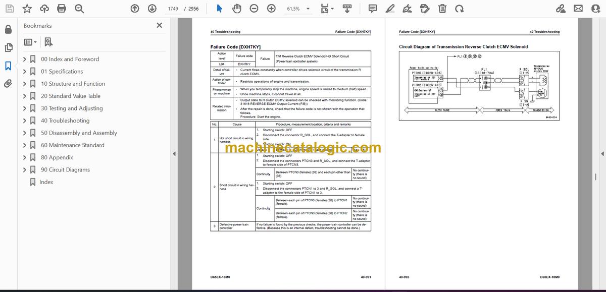
- Failure Code [DXH7KA]
- Failure Code [DXH7KB]
- Failure Code [DXH7KY]
- Failure Code [DXH8KA]
- Failure Code [DXH8KB]
- Failure Code [DXH8KY]
- Failure Code [DXJ4KA]
- Failure Code [DXJ4KB]
- Failure Code [F311KA]
- Failure Code [F311KB]
- Failure Code [F312KA]
- Failure Code [F312KB]
- Failure Code [F313KA]
- Failure Code [F313KB]
- Failure Code [F314KA]
- Failure Code [F314KB]
- Failure Code [F315KB]
- Failure Code [F315KY]
- Failure Code [F316KB]
- Failure Code [F316KY]
- Failure Code [F318KB]
- Failure Code [F318KY]
- Failure Code [F31AKB]
- Failure Code [F31AKY]
- Failure Code [F31BKB]
- Failure Code [F31BKY]
- Failure Code [F31CKB]
- Failure Code [F31CKY]
- Failure Code [F31DKB]
- Failure Code [F31DKY]
- Failure Code [F31EKB]
- Failure Code [F31EKY]
- Failure Code [FS10ZE]
- Troubleshooting of Electrical System (E-Mode)
- Engine Does Not Start (Engine Does Not Crank)
- Manual Preheating System Does Not Operate
- Automatic Preheating System Does Not Operate
- While Preheating is in Operation, Preheating Monitor Does Not Come On
- When Starting Switch is Turned to ON Position, Machine Monitor Shows Nothing
- When Starting Switch is Turned to ON Position (with Engine Stopped), Basic Check Monitor Comes On
- Air Cleaner Clogging Monitor Comes On in Yellow While Engine is in Operation
- Charge Level Monitor Comes On in Red While Engine is in Operation
- Engine Coolant Temperature Monitor Comes On in Red While Engine is in Operation
- Engine Oil Pressure Monitor Comes On in Red While Engine is in Operation
- Power Train Oil Temperature Monitor Comes On in Red While Engine Runs
- Hydraulic Oil Temperature Monitor Comes On in Red While Engine is in Operation
- Engine Coolant Temperature Gauge Does Not Show Correct Temperature
- DEF Level is Not Shown Correctly
- Fuel Gauge Does Not Show Normally
- Power Train Oil Temperature Gauge Does Not Show Correct Temperature
- Hydraulic Oil Temperature Gauge Does Not Show Correct Temperature
- Operation Mode Does Not Change
- Gear Shift Mode Does Not Change
- When You Operate Customize Switch Does Not Show Customize Screen
- When You Change Setting on Customize Screen, Setting of Machine is Not Changed
- Some Areas of Machine Monitor Screen are Not Shown
- REVERSE Slow Mode Function Does Not Operate Correctly
- Alarm Buzzer Does Not Operate or Does Not Stop Operation
- Service Meter is Not Shown While Starting Switch is in OFF Position
- Service Mode Cannot be Selected
- Horn Does Not Sound
- Horn Does Not Stop
- Backup Alarm Does Not Sound
- Backup Alarm Does Not Stop Operation
- Headlamp Does Not Come On
- Rear Lamp Does Not Come On
- No Wiper Operates
- Front Wiper Does Not Operate
- Rear Wiper Does Not Operate
- Left Door Wiper Does Not Operate
- Right Door Wiper Does Not Operate
- Front Washer Does Not Operate
- Rear Washer Does Not Operate
- Left Door Washer Does Not Operate
- Right Door Washer Does Not Operate
- KOMTRAX System Does Not Operate Correctly
- Troubleshooting for Hydraulic and Mechanical Systems (H Mode)
- Information Shown in Troubleshooting Table (H-Mode)
- System Chart of Hydraulic and Mechanical Systems
- Failure Mode and Cause Table
- Machine Lacks Power (Drawbar Pull is Not Sufficient)
- Machine Does Not Travel (at 2nd or 3rd Gear Speed)
- Machine Does Not Move Off at All Gear Speeds
- Machine Travels Only in One Direction, Forward or in Reverse
- Large Time Lag is in Gear Shifting or Directional Change
- Brake Does Not Work
- Power Train Oil Overheats
- Unusual Noise is Heard from Around Work Equipment and HSS Pump or HSS Motor
- Torque Converter Lockup Clutch Does Not Engage
- Machine Cannot be Steered (Machine Does Not Turn LEFT or RIGHT)
- Steering Speed or Power is Not Sufficient
- All Work Equipment Operate Slowly
- All Work Equipment Do Not Operate
- Blade Lift Speed or Power is Low
- Blade Tilt Speed or Power is Low
- Blade Angle Speed or Power is Low
- Ripper Lift Speed or Power is Low
- Hydraulic Drift of Blade Lift is Large
- Hydraulic Drift of Tilted Blade is Large
- Hydraulic Drift of Lifted Ripper is Large
- Fan Speed is Abnormal (Too High or Low, or Does Not Rotate)
- Unusual Noise is Heard from Around Fan
- Troubleshooting of Engine (S-Mode)
- Information Shown in Troubleshooting Table (S-Mode)
- Engine Does Not Crank When Starting Switch is Turned to Start Position
- Engine Cranks but No Exhaust Smoke Comes Out
- Fuel is Sprayed but Engine Does Not Start (Misfiring: Engine Cranks but Does Not Start)
- Engine Startability is Unsatisfactory
- Engine Does Not Pick Up Smoothly
- Engine Stops During Operation
- Engine Does Not Rotate Smoothly
- Engine Lacks Power
- KDPF Becomes Clogged in a Short Time
- Engine Oil Consumption is Excessive
- Engine Oil Becomes Dirty Quickly
- Fuel Consumption is Excessive
- Oil is in Coolant (or Coolant Spurts Back or Coolant Level Goes Down)
- Engine Oil Pressure Drops
- Fuel Mixes Into Engine Oil
- Water Mixes Into Engine Oil (Milky)
- Coolant Temperature Becomes Too High (Overheating)
- Unusual Noise is Heard
- Vibration is Excessive
- Air Cannot be Bled from Fuel Circuit
- Active Regeneration is Done Frequently
- Active Regeneration Continues Long
- White Smoke is Exhausted During Active Regeneration
- DEF Consumption is Excessive
- There is an Unusual Smell (Irritating Odor)
- Foreign Materials Enter DEF (DEF Increases)
- 50 Disassembly and Assembly
- Table of Contents
- Precautions Before Work
- Related Information on Disassembly and Assembly
- How to Read This Manual
- Coating Materials List
- Special Tool List
- Sketches of Special Tools
- Engine and Cooling System
- Remove and Install Supply Pump Assembly
- How to Remove Supply Pump Assembly
- How to Install Supply Pump Assembly
- Remove and Install Injector Assembly
- How to Remove Injector Assembly
- How to Install Injector Assembly
- Remove and Install Cylinder Head Assembly
- How to Remove Cylinder Head Assembly
- How to Install Cylinder Head Assembly
- Remove and Install EGR Valve Assembly
- How to Remove EGR Valve Assembly
- How to Install EGR Valve Assembly
- Remove and Install EGR Cooler Assembly
- How to Remove EGR Cooler Assembly
- How to Install EGR Cooler Assembly
- Remove and Install Starter Assembly
- How to Remove Starting Motor Assembly
- How to Install Starting Motor Assembly
- Remove and Install Alternator Belt
- How to Remove Alternator Belt
- How to Install Alternator Belt
- Remove and Install Automatic Tensioner
- How to Remove Automatic Tensioner
- How to Install Automatic Tensioner
- Remove and Install Expansion Tank Assembly
- How to Remove Expansion Tank Assembly
- How to Install Expansion Tank Assembly
- Remove and Install Radiator Assembly
- How to Remove Radiator Assembly
- How to Install Radiator Assembly
- Remove and Install Hydraulic Oil Cooler Assembly
- How to Remove Hydraulic Oil Cooler Assembly
- How to Install Hydraulic Oil Cooler Assembly
- Remove and Install Aftercooler Assembly
- How to Remove Aftercooler Assembly
- How to Install Aftercooler Assembly
- Remove and Install Power Train Oil Cooler Assembly
- How to Remove Power Train Oil Cooler Assembly
- How to Install Power Train Oil Cooler Assembly
- Remove and Install Cooling Fan Drive Assembly
- How to Remove Cooling Fan Drive Assembly
- How to Install Cooling Fan Drive Assembly
- Remove and Install Cooling Fan Motor Assembly
- How to Remove Cooling Fan Motor Assembly
- How to Install Cooling Fan Motor Assembly
- Remove and Install Engine Assembly
- How to Remove Engine Assembly
- How to Install Engine Assembly
- Remove and Install Engine Front Oil Seal
- How to Remove Engine Front Oil Seal
- How to Install Engine Front Oil Seal
- Remove and Install Engine Rear Oil Seal
- How to Remove Engine Rear Oil Seal
- How to Install Engine Rear Oil Seal
- Remove and Install Engine Hood Assembly
- How to Remove Engine Hood Assembly
- How to Install Engine Hood Assembly
- Remove and Install Fuel Tank Assembly
- How to Remove Fuel Tank Assembly
- How to Install Fuel Tank Assembly
- Remove and Install DEF Tank Assembly
- How to Remove DEF Tank Assembly
- How to Install DEF Tank Assembly
- Remove and Install DEF Tank Sensor Flange Assembly
- How to Remove DEF Tank Sensor Flange Assembly
- How to Install DEF Tank Sensor Flange Assembly
- Remove and Install DEF Tank Sensor
- How to Remove DEF Tank Sensor
- How to Install DEF Tank Sensor
- Remove and Install DEF Tank Strainer
- How to Remove DEF Tank Strainer
- How to Install DEF Tank Strainer
- Remove and Install KDPF Assembly
- How to Remove KDPF Assembly
- How to Install KDPF Assembly
- Disassemble and Assemble KDPF Assembly
- How to Disassemble KDPF Assembly
- How to Assemble KDPF Assembly
- Remove and Install SCR Assembly
- How to Remove SCR Assembly
- How to Install SCR Assembly
- Remove and Install KDPF and SCR Assembly
- How to Remove KDPF and SCR Assembly
- How to Install KDPF and SCR Assembly
- Remove and Install KCCV Assembly
- How to Remove KCCV Assembly
- How to Install KCCV Assembly
- Remove and Install DEF Mixing Tube
- How to Remove DEF Mixing Tube
- How to Install DEF Mixing Tube
- Remove and Install DEF Injector
- How to Remove DEF Injector
- How to Install DEF Injector
- Remove and Install DEF Pump
- How to Remove DEF Pump
- How to Install DEF Pump
- Remove and Install DEF Hose
- How to Remove DEF Hose
- How to Install DEF Hose
- Remove and Install Air Cleaner Assembly
- How to Remove Air Cleaner Assembly
- How to Install Air Cleaner Assembly
- Remove and Install Air Conditioner Compressor Assembly
- How to Remove Air Conditioner Compressor Assembly
- How to Install Air Conditioner Compressor Assembly
- Remove and Install Air Conditioner Condenser Assembly
- How to Remove Air Conditioner Condenser Assembly
- How to Install Air Conditioner Condenser Assembly
- Power Train
- Remove and Install Damper Assembly
- How to Remove Damper Assembly
- How to Install Damper Assembly
- Remove and Install Power Train Unit Assembly
- How to Remove Power Train Unit Assembly
- How to Install Power Train Unit Assembly
- Disconnect and Connect Power Train Unit Assembly
- How to Disconnect Power Train Unit Assembly
- How to Connect Power Train Unit Assembly
- Disassemble and Assemble PTO Assembly
- How to Disassemble PTO Assembly
- How to Assemble PTO Assembly
- Disassemble and Assemble Torque Converter Assembly
- How to Disassemble Torque Converter Assembly
- How to Assemble Torque Converter Assembly
- Disassemble and Assemble Transmission Assembly
- How to Disassemble Transmission Assembly
- How to Assemble Transmission Assembly
- Disassemble and Assemble HSS Assembly
- How to Disassemble HSS Assembly
- How to Assemble HSS Assembly
- Remove and Install HSS Motor Assembly
- How to Remove HSS Motor Assembly
- How to Install HSS Motor Assembly
- Remove and Install Final Drive Assembly
- How to Remove Final Drive Assembly
- How to Install Final Drive Assembly
- Disassemble and Assemble Final Drive Assembly
- How to Disassemble Final Drive Assembly
- How to Assemble Final Drive Assembly
- Undercarriage and Frame
- Remove and Install Track Frame Assembly
- How to Remove Track Frame Assembly
- How to Install Track Frame Assembly
- Remove and Install Idler Assembly
- How to Remove Idler Assembly
- How to Install Idler Assembly
- Disassemble and Assemble Idler Assembly
- How to Disassemble Idler Assembly
- How to Assemble Idler Assembly
- Remove and Install Recoil Spring Assembly
- How to Remove Recoil Spring Assembly
- How to Install Recoil Spring Assembly
- Disassemble and Assemble Recoil Spring Assembly
- How to Disassemble Recoil Spring Assembly
- How to Assemble Recoil Spring Assembly
- Remove and Install Track Roller Assembly
- How to Remove Track Roller Assembly
- How to Install Track Roller Assembly
- Disassemble and Assemble Track Roller Assembly
- How to Disassemble Track Roller Assembly
- How to Assemble Track Roller Assembly
- Remove and Install Carrier Roller Assembly
- How to Remove Carrier Roller Assembly
- How to Install Carrier Roller Assembly
- Disassemble and Assemble Carrier Roller Assembly
- How to Disassemble Carrier Roller Assembly
- How to Assemble Carrier Roller Assembly
- Remove and Install Pivot Shaft Assembly
- How to Remove Pivot Shaft Assembly
- How to Install Pivot Shaft Assembly
- Separate and Connect Track Assembly
- How to Examine Before Separation of Track Assembly
- How to Separate Track Assembly (Standard)
- How to Separate Track Assembly (When Track Frame Has Internal Defect)
- How to Install Track Assembly
- Separate and Connect PLUS Type Track Assembly
- How to Separate PLUS Type Track Assembly
- Install PLUS Type Track Assembly
- Disassemble and Assemble Track Assembly Generally
- How to Disassemble Full Track Shoes Assembly
- How to Assemble Full Track Shoes Assembly
- Disassemble and Assemble PLUS Type Track Assembly Generally
- Disassemble PLUS Type Track Assembly Generally
- How to Assemble PLUS Type Track Shoes Assembly Generally
- Disassemble and Assemble One Track Link Assembly in Field (Track Assembly)
- How to Disassemble One Track Link Assembly in Field (Track Assembly)
- How to Assemble One Track Link Assembly in Field (Track Assembly)
- Disassemble and Assemble One Track Link Assembly in Field (PLUS Type Track Assembly)
- How to Disassemble One Track Link Assembly in Field (PLUS Type Track Assembly)
- Assemble One Track Link Assembly in Field (PLUS Type Track Assembly)
- Remove and Install Equalizer Bar Assembly
- How to Remove Equalizer Bar Assembly
- How to Install Equalizer Bar Assembly
- Disassemble and Assemble Equalizer Bar Bushing
- How to Disassemble Equalizer Bar Bushing
- How to Assemble Equalizer Bar Bushing
- Hydraulic System
- Remove and Install Hydraulic Tank Assembly
- How to Remove Hydraulic Tank Assembly
- How to Install Hydraulic Tank Assembly
- Remove and Install HSS Pump and Cooling Fan Pump Assembly
- How to Remove HSS Pump and Cooling Fan Pump Assembly
- How to Install HSS Pump and Cooling Fan Pump Assembly
- Remove and Install Power Train Pump and Steering Lubrication Pump Assembly
- How to Remove Power Train Pump and Steering Lubrication Pump Assembly
- How to Install Power Train Pump and Steering Lubrication Pump Assembly
- Remove and Install Scavenging Pump Assembly
- How to Remove Scavenging Pump Assembly
- How to Install Scavenging Pump Assembly
- Remove and Install 5 Spool Control Valve Assembly
- How to Remove 5 Spool Control Valve Assembly
- How to Install 5 Spool Control Valve Assembly
- Remove and Install 4 Spool Control Valve Assembly
- How to Remove 4 Spool Control Valve Assembly
- How to Install 4 Spool Control Valve Assembly
- Disassemble and Assemble Blade PPC Valve
- How to Disassemble Blade PPC Valve
- How to Assemble Blade PPC Valve
- Disassemble and Assemble Ripper PPC Valve
- How to Disassemble Ripper PPC Valve
- How to Assemble Ripper PPC Valve
- Work Equipment
- Remove and Install Straight Tilt Power Pitch Dozer Blade Assembly
- How to Remove Straight Tilt Power Pitch Dozer Blade Assembly
- How to Install Straight Tilt Power Pitch Dozer Blade Assembly
- Remove and Install Ripper Assembly
- How to Remove Ripper Assembly
- How to Install Ripper Assembly
- How to Disassemble and Assemble Work Equipment Cylinder Assembly
- How to Disassemble Work Equipment Cylinder Assembly
- How to Assemble Work Equipment Cylinder Assembly
- CAB Related Parts
- Remove and Install Operator Cab Assembly
- How to Remove Operator Cab Assembly
- How to Install Operator Cab Assembly
- Remove and Install Operator Cab Glass (Adhered Glass)
- How to Remove Operator Cab Glass (Adhered Glass)
- How to Install Operator Cab Glass (Adhered Glass)
- Remove and Install Air Conditioner Unit Assembly
- How to Remove Air Conditioner Unit Assembly
- How to Install Air Conditioner Unit Assembly
- Remove and Install Operator Seat
- How to Remove Operator Seat
- How to Install Operator Seat
- How to Remove and Install Seat Belt
- How to Remove Seat Belt
- How to Install Seat Belt
- Electrical System
- Remove and Install Engine Controller Assembly
- How to Remove Engine Controller Assembly
- How to Install Engine Controller Assembly
- Remove and Install Power Train Controller Assembly
- How to Remove Power Train Controller Assembly
- How to Install Power Train Controller Assembly
- Remove and Install Machine Monitor Assembly
- How to Remove Machine Monitor Assembly
- How to Install Machine Monitor Assembly
- Remove and Install Mass Air Flow and Temperature Sensor
- How to Remove Mass Air Flow and Temperature Sensor
- How to Install Mass Air Flow and Temperature Sensor
- Remove and Install KCCV Crankcase Pressure Sensor
- How to Remove KCCV Crankcase Pressure Sensor
- How to Install KCCV Crankcase Pressure Sensor
- Remove and Install SCR Temperature Sensor
- How to Remove SCR Temperature Sensor
- How to Install SCR Temperature Sensor
- Remove and Install Rearview Camera
- How to Remove Rearview Camera
- How to Install Rearview Camera
- Remove and Install KOMTRAX Terminal Assembly
- How to Remove KOMTRAX Terminal Assembly
- How to Install KOMTRAX Terminal Assembly
- Remove and Install Gateway Function Controller Assembly
- How to Remove Gateway Function Controller Assembly
- How to Install Gateway Function Controller Assembly
- Remove and Install Communication Terminal
- How to Remove Communication Terminal
- How to Install Communication Terminal
- 60 Maintenance Standard
- Table of Contents
- Explanation of Terms for Maintenance Standard
- Engine and Cooling System
- Maintenance Standard for Engine Mount
- Maintenance Standard for Damper (Applicable Machine: 96001 to 96680)
- Maintenance Standard for Damper (Applicable Machine: 96681 and up)
- Maintenance Standard for Cooling System
- Maintenance Standard for Cooling Fan Pump
- Maintenance Standard for Servo Valve
- Maintenance Standard for Cooling Fan Motor
- Power Train
- Maintenance Standard for Universal Joint
- Maintenance Standard for Power Train Mount
- Maintenance Standard for Torque Converter and PTO
- Maintenance Standard for Lockup Clutch ECMV
- Maintenance Standard for Transmission
- Maintenance Standard for Transmission Control Valve
- Maintenance Standard for Forward and Reverse Clutch ECMV and Gear Speed Clutch ECMV
- Maintenance Standard for Main Relief Valve and Torque Converter Relief Valve
- Maintenance Standard for Transmission Lubrication Relief Valve
- Maintenance Standard for Bevel Gear Shaft, HSS, and Brake
- Maintenance Standard for Brake Valve
- Maintenance Standard for Final Drive
- Maintenance Standard for Sprocket for Conventional Type Track Shoes
- Maintenance Standard for Sprocket Tooth Profile Full-Scale Drawing for Conventional Type Track Shoes
- Maintenance Standard for Sprocket for PLUS Type Track Shoes
- Maintenance Standard for Sprocket Tooth Profile Full-Scale Drawing for PLUS Type Track Shoes
- Undercarriage and Frame
- Maintenance Standard for Main Frame
- Maintenance Standard for Suspension
- Maintenance Standard for Track Frame and Idler Cushion
- Maintenance Standard for Idler
- Maintenance Standard for Track Roller for Conventional Type Track Shoes (Single Flange Type)
- Maintenance Standard for Track Roller for Conventional Type Track Shoes (Double Flange Type)
- Maintenance Standard for Track Roller for PLUS Type Track Shoes (Single Flange Type)
- Maintenance Standard for Track Roller for PLUS Type Track Shoes (Double Flange Type)
- Maintenance Standard for Carrier Roller for Conventional Type Track Shoes
- Maintenance Standard for Carrier Roller for PLUS Type Track Shoes
- Maintenance Standard for Conventional Type Track Shoes
- Maintenance Standard for PLUS Type Track Shoes
- Maintenance Standard for Single Shoes
- Maintenance Standard for Swamp Shoes
- Hydraulic System
- Maintenance Standard for Hydraulic Tank
- Maintenance Standard for Scavenging Pump
- Maintenance Standard for Steering Lubrication Pump and Power Train Pump
- Maintenance Standard for Work Equipment and HSS Pump
- Maintenance Standard for PC-EPC Valve
- Maintenance Standard for HSS Motor
- Maintenance Standard for Control Valve
- Maintenance Standard for Blade PPC Valve
- Maintenance Standard for Ripper PPC Valve
- Maintenance Standard for Quick Drop Valve
- Maintenance Standard for Work Equipment Lock Solenoid Valve (For Tilt Dozer and Angle Dozer Series)
- Maintenance Standard for Work Equipment Lock Solenoid Valve (For Power Tilt Pitch Dozer Series)
- Work Equipment
- Maintenance Standard for Front Work Equipment (For Tilt Dozer and Power Tilt Pitch Dozer Series)
- Maintenance Standard for Front Work Equipment (Angle Dozer Series)
- Maintenance Standard for Front Work Equipment (Trimming Dozer Specification)
- Maintenance Standard for Cutting Edge and End Bit
- Maintenance Standard for Blade Lift Cylinder (For Tilt Dozer and Power Tilt Pitch Dozer, and Angle Dozer Series)
- Maintenance Standard for Blade Lift Cylinder (Trimming Dozer Specification)
- Maintenance Standard for Blade Tilt Cylinder (For Tilt Dozer and Power Tilt Pitch Dozer, and Angle Dozer Series)
- Maintenance Standard for Blade Pitch Cylinder (For Power Tilt Pitch Dozer Series)
- Maintenance Standard for Trimming Cylinder (Trimming Dozer Specification)
- Maintenance Standard for Fixed Multi-Shank Ripper
- Maintenance Standard for Ripper Lift Cylinder
- CAB Related Parts
- Maintenance Standard for CAB Mount
- 80 Appendix
- Table of Contents
- Precautions Before Work
- Air Conditioner System
- Precautions for Refrigerant
- Air Conditioner Component
- Specifications of Air Conditioner
- Structure and Function of Refrigeration Cycle
- Outline of Refrigeration Cycle
- Component Parts of Air Conditioner System
- Air Conditioner Unit
- Configuration Diagram of Air Conditioner Unit
- Function of Air Conditioner Unit
- Component Parts of Air Conditioner Unit
- Function of Evaporator as Air Conditioner Unit Component
- Function of Heater Core as Air Conditioner Unit Component
- Function of Evaporator Temperature Sensor as Air Conditioner Unit Component
- Function of Servo Motor as Air Conditioner Unit Component
- Structure of Expansion Valve as Air Conditioner Unit Component
- Function of Expansion Valve as Air Conditioner Unit Component
- Operate Expansion Valve as Air Conditioner Unit Component
- Function of Dual Pressure Switch
- Air Conditioner Controller
- Structure of Air Conditioner Controller
- Compressor
- Structure of Compressor
- Specifications of Compressor
- Function of Compressor
- Condenser
- Structure of Standard Core Condenser
- Specifications of Standard Core Condenser
- Function of Standard Core Condenser
- Structure of Wide Core Condenser
- Specifications of Wide Core Condenser
- Function of Wide Core Condenser
- Receiver Drier
- Structure of Receiver Dryer
- Specifications of Receiver Dryer
- Function of Receiver Dryer
- Air Conditioner Related Sensors
- Structure of Sunlight Sensor
- Function of Sunlight Sensor
- Structure of Outside Temperature Sensor
- Function of Outside Air Temperature Sensor
- Explanation of Procedure for Test of and Troubleshooting of Air Conditioner
- Circuit Diagram and Configuration of Connector Pins of Air Conditioner
- System Diagram of Air Conditioner
- Input and Output Signals of Air Conditioner Controller
- Function of Air Conditioner Controller
- Locations of Air Conditioner Parts and Layout of Connectors
- Examine Air Leakage (Duct)
- How to Examine Air Leakage (Duct)
- Explanation for Test of Air Conditioner with Self-Diagnosis Function
- Open the Electrical System Abnormality Record Screen in Service Mode of Machine Monitor
- Examine Vent (Mode) Changeover
- How to Examine Vent (Mode) Changeover
- Examine Fresh/Recirc Air Changeover
- How to Examine Fresh/Recirc Air Changeover
- Examine Sunlight Sensor
- How to Examine Sunlight Sensor
- Examine Refrigerant (Dual) Pressure Switch
- How to Examine Refrigerant (Dual) Pressure Switch
- Examine Relay
- Air Conditioner Troubleshooting Chart 1
- Air Conditioner Troubleshooting Chart 2
- Information Shown in Troubleshooting Table
- Failure Code [879AKA]
- Failure Code [879AKB]
- Failure Code [879BKA]
- Failure Code [879BKB]
- Failure Code [879CKA]
- Failure Code [879CKB]
- Failure Code [879DKZ]
- Failure Code [879EMC]
- Failure Code [879FMC]
- Failure Code [879GKX]
- Troubleshooting for Power Supply System (Air Conditioner Does Not Operate)
- Troubleshooting for Compressor and Refrigerant System (Air is Not Cooled)
- Troubleshooting for Blower Motor System (No Air Comes Out or Air Flow is Abnormal)
- Troubleshooting for Fresh/Recirc Air Changeover
- Troubleshooting by Gauge Pressure
- Connect Service Tool
- How to Connect Service Tool
- Precautions for Disconnection and Connection of Air Conditioner Piping
- Handle Compressor Oil
- 90 Circuit Diagrams
- Table of Contents
- How to Read the Codes for Electric Cable
- Hydraulic Circuit Diagram
- Symbols Used in Hydraulic Circuit Diagram
- Hydraulic Circuit Diagram
- Power Train Hydraulic Circuit Diagram
- Electrical Circuit Diagram
- Symbols Used in Electric Circuit Diagram
- Electrical Circuit Diagram (1/13)
- Electrical Circuit Diagram (2/13)
- Electrical Circuit Diagram (3/13)
- Electrical Circuit Diagram (4/13)
- Electrical Circuit Diagram (5/13)
- Electrical Circuit Diagram (6/13)
- Electrical Circuit Diagram (7/13)
- Electrical Circuit Diagram (8/13)
- Electrical Circuit Diagram (9/13)
- Electrical Circuit Diagram (10/13)
- Electrical Circuit Diagram (11/13)
- Electrical Circuit Diagram (12/13)
- Electrical Circuit Diagram (13/13)
- Index
Komatsu


