These Komatsu PC600-8R and PC600LC-8R crawler excavators are heavy production machines—rock, bulk earthmoving, quarry work, demolition. This kind of Shop Manual is what the workshop or field service tech reaches for when a fault code won’t clear, a major component needs to come off, or you’re planning a rebuild instead of just swapping parts. If you’re trying to control downtime and parts spend across a fleet, this is the book that underpins your repair standards.
What this manual helps you do
- Trace hydraulic and electrical faults using system layouts and step‑by‑step diagnostic routines for the PC600-8R and PC600LC-8R.
- Check engine, swing, and travel systems with the test procedures you’d expect in a Komatsu shop manual, so you don’t shotgun parts.
- Follow disassembly and reassembly sequences for major components like pumps, final drives, cylinders, and swing machinery.
- Diagnose performance issues in the powertrain and working equipment and tie symptoms back to likely causes before you order parts.
- Handle adjustments and post‑repair checks so machines go back to work once, not back to the shop twice.
Who this is for
This Komatsu PC600-8R, PC600LC-8R Crawler Excavator Shop Manual (SEN02402-21) is aimed at field techs, shop mechanics, and fleet managers setting repair procedures and preventive schedules. It’s not an operator’s handbook; if you just need daily checks and basic maintenance, you want the Operation & Maintenance Manual instead.
FAQ
Q: Is this a searchable PDF I can download and print?
A: Yes, it’s a PDF you can download, search on a laptop or tablet, and print working sections for the shop.
Q: Is this deep enough for component overhaul, or only basic service?
A: This kind of shop manual is intended for workshop‑level diagnostics, removal, disassembly, inspection, and reassembly of major systems.
Q: How do I know it matches my exact machine variant?
A: Check your machine model and book reference; if your excavator is a PC600-8R or PC600LC-8R and you’re matching to SEN02402-21, you’re in the right place.
Bottom line: If you’re responsible for serious repairs and want consistent, planned work on PC600-8R/PC600LC-8R units, this is the right manual; if you just run the machines and do light service, keep looking for the O&M book instead.
📘 Show Index
Table of Contents:
- 00 Index and foreword
- Index
- Composition of shop manual
- Table of contents
- Foreword and general information
- Safety notice
- How to read the shop manual
- Explanation of terms for maintenance standard
- Handling of electric equipment and hydraulic component
- Handling of connectors newly used for engines
- How to read electric wire code
- Precautions when carrying out operation
- Method of disassembling and connecting push-pull type coupler
- Standard tightening torque table
- Conversion table
- 01 Specification
- Specification and technical data
- Specification drawings
- Working range drawings
- Specifications
- Weight table
- Table of fuel, coolant and lubricants
- 10 Structure, function and maintenance standard
- Engine and cooling system
- Parts related to engine
- PTO
- Fan, control and PTO lubrication pump
- Radiator, oil cooler
- Power train
- Power train
- Final drive
- Sprocket
- Swing circle
- Swing machinery
- Undercarriage and frame
- Track frame, recoil spring
- Idler
- Carrier roller
- Track roller
- Track shoe
- Hydraulic system, Part 1
- Hydraulic piping drawing
- Hydraulic tank, hydraulic filter
- Hydraulic pump (piston pump)
- Line oil filter
- Cooling fan pump
- Cooling fan motor
- Hydraulic system, Part 2
- Control valve
- Swing motor
- Swing brake
- Safety valve
- Reverse prevention valve
- Center swivel joint
- Travel motor
- Parking brake
- Brake valve
- Set pressures varying mechanism
- Valve control
- Work equipment, swing PPC valve
- Travel PPC valve
- Service PPC valve
- PPC accumulator
- PPC shuttle valve
- Solenoid valve
- Boom holding valve
- Boom LOWER regeneration valve
- Quick return valve
- Hydraulic cylinder
- Work equipment
- Work equipment
- Dimensions of work equpment
- Cab and its attachments
- Electrical system
- Engine control
- Machine control system diagram
- Monitor system
- Sensors
- KOMTRAX system
- 20 Standard value table
- Standard service value table
- Standard value table for engine
- Standard value table for chassis
- 30 Testing and adjusting
- Testing and adjusting, Part 1
- Tools for testing, adjusting and troubleshooting
- Measuring engine speed
- Measuring intake air pressure (boost pressure)
- Measuring exhaust gas temperature
- Measuring exhaust gas color
- Adjusting valve clearance
- Measuring compression pressure
- Measuring blow-by pressure
- Measuring engine oil pressure
- Handling equipment in fuel circuit
- Releasing remaining pressure in fuel system
- Measuring fuel pressure
- Reduced cylinder mode operation
- No-injection cranking
- Testing leakage from pressure limiter and return rate from injector
- Bleeding air from fuel circuit
- Testing fuel system for leakage
- Testing and adjusting alternator belt tension
- Testing and adjusting air conditioner compressor belt tension
- Testing clearance of swing circle bearing
- Testing and adjusting track shoe tension
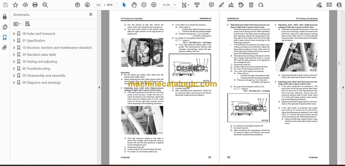
- Testing and adjusting work equipment, swing, and travel circuit oil pressures
- Testing and adjusting control circuit oil pressure
- Testing and adjusting piston pump control oil pressure
- Testing servo piston stroke
- Measuring PPC valve output pressure
- Measuring outlet pressures of solenoid valve and PPC shuttle valve
- Adjusting work equipment, swing PPC valve
- Testing and adjusting travel deviation
- Measuring fan speed
- Measuring fan circuit oil pressure
- Inspection of locations of hydraulic drift of work equipment
- Measuring oil leakage
- Releasing remaining pressure in hydraulic circuit
- Bleeding air from each part
- Inspection procedures for diode
- Testing and adjusting, Part 2
- Special function of machine monitor
- Handling controller voltage circuit
- Procedure for turning on KOMTRAX terminal
- KOMTRAX terminal lamp indications
- Preparation work for troubleshooting electrical system
- Adjusting mirrors
- Pm-CLINIC SERVICE
- Pm-CLINIC SERVICE PC600, 600LC-8R
- UNDERCARRIAGE INSPECTION
- 40 Troubleshooting
- Failure code table and fuse locations
- Failure codes table
- Fuse locations
- General information on troubleshooting
- Points to remember when troubleshooting
- Sequence of events in troubleshooting
- Checks before troubleshooting
- Classification and procedures of troubleshooting
- Connection table for connector pin numbers
- T- branch box and T- branch adapter table
- Troubleshooting by failure code (Display of code), Part 1
- Failure code [AA10NX] Aircleaner clogging
- Failure code [AB00KE] Charge Voltage Low
- Failure code [B@BAZG] Eng Oil Press. Low
- Failure code [B@BAZK] Eng. Oil Level Low
- Failure code [B@BCNS] Eng. Water Overheat
- Failure code [B@BCZK] Eng. Water Lvl Low
- Failure code [B@HANS] Hydr. Oil Overheat
- Failure code [CA111] ECM Critical Internal Failure
- Failure code [CA115] Eng Ne and Bkup Speed Sens Error
- Failure code [CA122] Chg Air Press Sensor High Error
- Failure code [CA123] Chg Air Press Sensor Low Error
- Failure code [CA131] Throttle Sensor High Error
- Failure code [CA132] Throttle Sensor Low Error
- Failure code [CA135] Eng Oil Press Sensor High Error
- Failure code [CA141] Eng Oil Press Sensor Low Error
- Failure code [CA144] Coolant Temp Sens High Error
- Failure code [CA145] Coolant Temp Sens Low Error
- Failure code [CA153] Chg Air Temp Sensor High Error
- Failure code [CA154] Chg Air Temp Sensor Low Error
- Failure code [CA187] Sens Supply 2 Volt Low Error
- Failure code [CA221] Ambient Press Sens High Error
- Failure code [CA222] Ambient Press Sens Low Error
- Failure code [CA227] Sens Supply 2 Volt High Error
- Failure code [CA234] Eng Overspeed
- Failure code [CA238] Ne Speed Sens Supply Volt Error
- Failure code [CA263] Fuel Temp Sensor High Error
- Failure code [CA265] Fuel Temp Sensor Low Error
- Failure code [CA271] IMV/PCV1 Short Error
- Failure code [CA272] IMV/PCV1 Open Error
- Failure code [CA273] PCV2 Short Error
- Failure code [CA274] PCV2 Open Error
- Troubleshooting by failure code (Display of code), Part 2
- Failure code [CA322] Inj #1 (L#1) Open/Short Error
- Failure code [CA323] Inj #5 (L#5) Open/Short Error
- Failure code [CA324] Inj #3 (L#3) Open/Short Error
- Failure code [CA325] Inj #6 (L#6) Open/Short Error
- Failure code [CA331] Inj #2 (L#2) Open/Short Error
- Failure code [CA332] Inj #4 (L#4) Open/Short Error
- Failure code [CA342] Calibration Code Incompatibility
- Failure code [CA351] Injectors Drive Circuit Error
- Failure code [CA352] Sens Supply 1 Volt Low Error
- Failure code [CA386] Sens Supply 1 Volt High Error
- Failure code [CA441] Battery Voltage Low Error
- Failure code [CA442] Battery Voltage High Error
- Failure code [CA449] Rail Press Very High Error
- Failure code [CA451] Rail Press Sensor High Error
- Failure code [CA452] Rail Press Sensor Low Error
- Failure code [CA553] Rail Press High Error
- Failure code [CA554] Rail Press Sensor In Range Error
- Failure code [CA559] Rail Press Low Error
- Failure code [CA689] Eng Ne Speed Sensor Error
- Failure code [CA731] Eng Bkup Speed Sens Phase Error
- Failure code [CA757] All Persistent Data Lost Error
- Failure code [CA778] Engine Bkup Speed Sensor Error
- Failure code [CA1633] KOMNET Datalink Timeout Error
- Failure code [CA2185] Throt Sens Sup Volt High Error
- Failure code [CA2186] Throt Sens Sup Volt Low Error
- Failure code [CA2249] Rail Press Very Low Error
- Failure code [CA2555] Grid Htr Relay Volt Low Error
- Failure code [CA2556] Grid Htr Relay Volt High Error
- Failure code [D110KB] Battery Relay Drive S/C
- Failure code [D163KB] Flash Light Relay S/C
- Failure code [D195KB] Step Light Relay S/C
- Failure code [DA22KK] Pump Solenoid Power Low Error
- Failure code [DA25KP] Press. Sensor Power Abnormality
- Failure code [DA2SKQ] Model Selection Abnormality
- Failure code [DA80MA] Auto. Lub Abnormal
- Troubleshooting by failure code (Display of code), Part 3
- Failure code [DA2RMC] Pump Comm. Abnormality
- Failure code [DAFRMC] Monitor Comm. Abnormality
- Failure code [DGE5KY] Ambi. Temp. Sensor S/C
- Failure code [DGH2KB] Hydr. Oil Temp. Sensor S/C
- Failure code [DHPAMA] F pump P. Sensor Abnormality
- Failure code [DHPBMA] R pump P. Sensor Abnormality
- Failure code [DV20KB] Travel Alarm S/C
- Failure code [DW43KA] Travel Speed Sol. Disc.
- Failure code [DW43KB] Travel Speed Sol. S/C
- Failure code [DW45KA] Swing Brake Sol. Disc.
- Failure code [DW45KB] Swing Brake Sol. S/C
- Failure code [DW48KA] CO Cancel Sol. Disc.
- Failure code [DW48KB] CO Cancel Sol. S/C
- Failure code [DW7BKA] Fan Reverse Sol. Disc.
- Failure code [DW7BKB] Fan Reverse Sol. S/C
- Failure code [DW4XKA] Bucket Curl Hi Cancel Sol. Disc.
- Failure code [DW4XKB] Bucket Curl Hi Cancel Sol. S/C
- Failure code [DWK0KA] 2-stage Relief Sol. Disc.
- Failure code [DWK0KB] 2-stage Relief Sol. S/C
- Failure code [DX16KA] Fan Pump EPC Sol. Disc.
- Failure code [DX16KB] Fan Pump EPC Sol. S/C
- Failure code [DXA0KA] TVC Sol. Disc.
- Failure code [DXA0KB] TVC Sol. S/C
- Failure code [DY20KA] Wiper Working Abnormality
- Failure code [DY20MA] Wiper Parking Abnormality
- Failure code [DY2CKB] Washer Drive S/C
- Failure code [DY2DKB] Wiper Drive (For) S/C
- Failure code [DY2EKB] Wiper Drive (Rev) S/C
- Troubleshooting of electrical system (E-mode)
- E-1 Engine does not start (Engine does not rotate)
- E-2 Preheater does not operate
- E-3 Auto engine warm-up device does not work
- E-4 Auto-decelerator does not operate
- E-5 All work equipment, swing and travel do not move
- E-6 Power max. function does not operate
- E-7 Machine push-up function does not operate normally
- E-8 Any item is not displayed on machine monitor
- E-9 Part of display on machine monitor is missing
- E-10 Machine monitor displays contents irrelevant to the model
- E-11 Fuel level monitor red lamp lights up while engine is running
- E-12 Engine coolant temperature gauge does not display correctly
- E-13 Hydraulic oil temperature gauge does not display correctly
- E-14 Fuel gauge does not display correctly
- E-15 Swing lock monitor does not display correctly
- E-16 When monitor switch is operated, nothing is displayed
- E-17 Wiper and window washer do not work
- E-18 "Boom Raise" is not correctly displayed in monitoring function
- E-19 "Boom Lower" is not correctly displayed in monitoring function
- E-20 "Arm IN" is not correctly displayed in monitoring function
- E-21 "Arm OUT" is not correctly displayed in monitoring function
- E-22 "Bucket CURL" is not correctly displayed in monitoring function
- E-23 "Bucket DUMP" is not correctly displayed in monitoring function
- E-24 "Swing" is not correctly displayed in monitoring function
- E-25 "Travel" is not correctly displayed in monitoring function
- E-26 Air conditioner does not work
- E-27 Step light does not light up or go off
- E-28 Electric grease gun does not operate
- E-29 Travel alarm does not sound or does not stop sounding
- E-30 Electric priming pump does not operate or does not stop automatically
- E-31 Horn does not sound
- E-32 Bottom dump does not move
- Troubleshooting of hydraulic and mechanical system (H-mode)
- Before troubleshooting H-mode
- Information in troubleshooting table
- H-1 Speed or power of all work equipment, travel, and swing is low
- H-2 Engine speed lowers remarkably or engine stalls
- H-3 All work equipment, travel, and swing systems do not work
- H-4 Abnormal sound is heard from around pump
- H-5 Auto-decelerator is not reset
- H-6 Boom speed or power is low
- H-7 Arm speed or power is low
- H-8 Bucket speed or power is low
- H-9 Boom does not move
- H-10 Arm does not move
- H-11 Bucket does not move
- H-12 Bottom dump does not move
- H-13 Hydraulic drift of work equipment is large
- H-14 Time lag of work equipment is large
- H-15 Power max. function does not operate or stop
- H-16 Machine push-up function does not operate or stop
- H-17 When arm and boom, bucket are operated simultaneously, boom, bucket speed is low
- H-17 When bucket and boom, arm, swing, travel are operated simultaneously, boom, arm, swing, travel speed is low
- H-19 When arm and swing are operated simultaneously, swing speed is low
- H-20 Machine deviates in one direction
- H-21 Machine deviates largely at start
- H-22 Travel deviation is large during compound operation
- H-23 Travel speed or power is low
- H-24 Machine does not travel (only one track)
- H-25 Travel speed does not change
- H-26 Upper structure does not swing
- H-27 Swing speed or acceleration is low
- H-28 Upper structure overruns excessively when it stops swinging
- H-29 Large shock is made when upper structure stops swinging
- H-30 Large abnormal sound is made when upper structure stops swinging
- H-31 Hydraulic drift of swing is large
- Troubleshooting of engine (S-mode)
- Method of using troubleshooting chart
- S-1 Starting performance is poor
- S-2 Engine does not start
- S-3 Engine does not pick up smoothly
- S-4 Engine stops during operations
- S-5 Engine does not rotate smoothly
- S-6 Engine lacks output (or lacks power)
- S-7 Exhaust smoke is black (incomplete combustion)
- S-8 Oil consumption is excessive (or exhaust smoke is blue)
- S-9 Oil becomes contaminated quickly
- S-10 Fuel consumption is excessive
- S-11 Oil is in coolant (or coolant spurts back or coolant level goes down)
- S-12 Oil pressure drops
- S-13 Oil level rises (Entry of coolant or fuel)
- S-14 Coolant temperature becomes too high (overheating)
- S-15 Abnormal noise is made
- S-16 Vibration is excessive
- S-17 Air cannot be bled from fuel circuit
- 50 Disassembly and assembly
- General information on disassembly and assembly
- How to read this manual
- Coating materials list
- Special tools list
- Sketches of special tools
- Engine and cooling system, Part 1
- Removal and installation of engine, PTO and hydraulic pump assembly
- Removal and installation of radiator assembly
- Removal and installation of hydraulic oil cooler assembly
- Removal and installation of aftercooler assembly
- Removal and installation of fan motor assembly
- Removal and installation of fuel tank assembly
- Engine and cooling system, Part 2
- Removal and installation of fuel supply pump assembly
- Removal and installation of cylinder head assembly
- Removal and installation of fuel injector assembly
- Removal and installation of engine front seal
- Removal and installation of engine rear seal
- Power train
- Removal and installation of PTO assembly
- Disassembly and assembly of PTO assembly
- Removal and installation of swing motor and swing machinery assembly
- Disassembly and assembly of swing machinery assembly
- Removal and installation of swing circle assembly
- Disassembly and assembly of final drive assembly
- Undercarriage and frame
- Removal and installation of track shoe assembly
- Disassembly and assembly of 1 link in field
- Removal and installation of idler, recoil spring assembly
- Disassembly and assembly of idler assembly
- Disassembly and assembly of recoil spring assembly
- Removal and installation of track roller assembly
- Disassembly and assembly of track roller assembly
- Removal and installation of carrier roller assembly
- Disassembly and assembly of carrier roller assembly
- Removal and installation of revolving frame assembly
- Removal and installation of counterweight assembly
- Hydraulic system
- Removal and installation of hydraulic tank assembly
- Removal and installation of hydraulic pump assembly
- Removal and installation of control valve and solenoid valve assembly
- Disassembly and assembly of control valve assembly
- Disassembly and assembly of main control valve assembly
- Removal and installation of swing motor assembly
- Removal and installation of center swivel joint assembly
- Disassembly and assembly of center swivel joint assembly
- Disassembly and assembly of work equipment PPC valve assembly
- Disassembly and assembly of travel PPC valve assembly
- Disassembly and assembly of hydraulic cylinder assembly
- Disassembly and assembly of grease gun assembly
- Work equipment
- Removal and installation of bucket cylinder assembly (Backhoe specification)
- Removal and installation of bucket cylinder assembly (Loading shovel specification)
- Removal and installation of arm cylinder assembly (Backhoe specification)
- Removal and installation of arm cylinder assembly (Loading shovel specification)
- Removal and installation of boom cylinder assembly (Backhoe specification)
- Removal and installation of boom cylinder assembly (Loading shovel specification)
- Removal and installation of bottom dump cylinder assembly (Loading shovel specification)
- Removal and installation of bucket assembly (Backhoe specification)
- Removal and installation of bucket assembly (Loading shovel specification)
- Removal and installation of arm assembly (Backhoe specification)
- Removal and installation of arm assembly (Loading shovel specification)
- Removal and installation of boom assembly (Backhoe specification)
- Removal and installation of boom assembly (Loading shovel specification)
- Removal and installation of work equipment (Backhoe specification)
- Removal and installation of work equipment (Loading shovel specification)
- Cab and its attachments
- Removal and installation of operator’s cab
- Removal and installation of operator’s cab glass (stuck glass)
- Removal and installation of front window assembly
- Removal and installation of work equipment control lever assembly
- Electrical system
- Removal and installation of air conditioner unit assembly
- Removal and installation of engine controller assembly
- Removal and Installation of KOMTRAX terminal assembly
- Removal and installation of pump controller assembly
- Removal and installation of monitor assembly
- 90 Diagrams and drawings
- Hydraulic diagrams and drawings
- Hydraulic circuit diagram (1/4) (Backhoe specification)
- Hydraulic circuit diagram (2/4) (ATT specification)
- Hydraulic circuit diagram (3/4) (Loading shovel specification)
- Hydraulic circuit diagram (4/4) (Loading shovel specification)
- Electrical diagrams and drawings
- Electrical circuit diagram (1/6)
- Electrical circuit diagram (2/6)
- Electrical circuit diagram (3/6)
- Electrical circuit diagram (4/6)
- Electrical circuit diagram (5/6)
- Electrical circuit diagram (6/6)
- Connector arrangement diagram
- Electrical circuit diagram for air conditioner
Komatsu


